Abstract
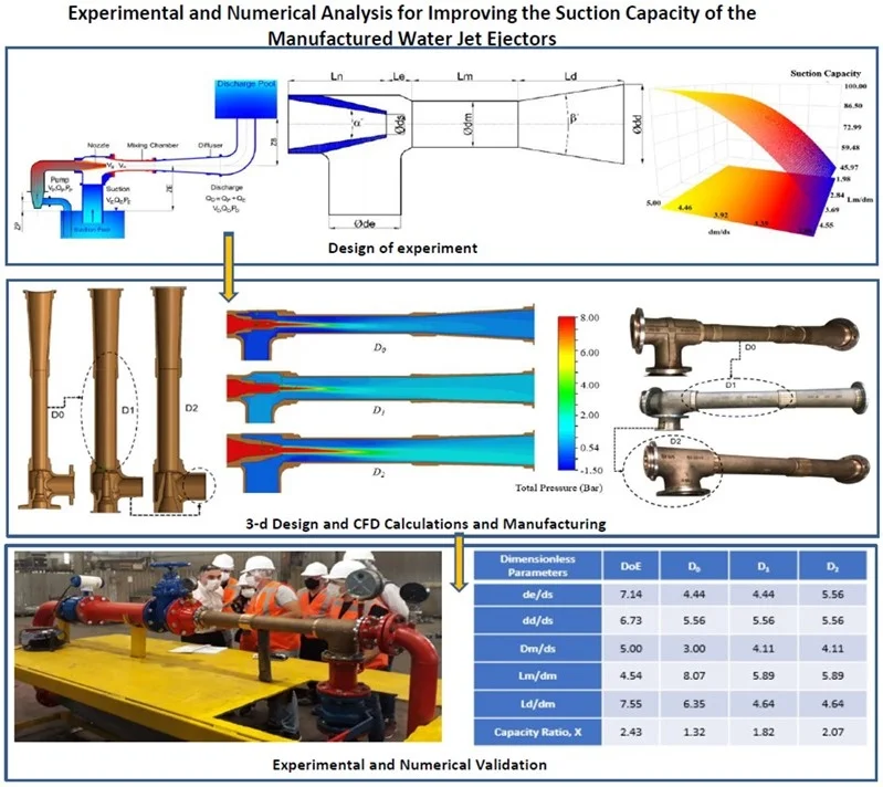
Water jet ejectors are the silent pumping fluid devices which doesn’t have any rotating parts in functional industrial applications. The dimensionless geometrical parameters effects ejector suction capacity. In this study, it is found that optimum design intervals have been determined by using the Response Surface Method (RSM). Design ranges determined in the dimensionless study have been used in the improvement of the suction capacity of an existing ejector. The suction capacity of the existing ejector is investigated via numerical and experimental analysis. Two new water jet ejector designs (D1 and D2) are built to improve the suction capacity of the initial water jet ejector (D0). The generated design parameters have been analyzed by using SolidWorks flow analysis and optimization software. The suction capacity of the ejector has been determined through the iterative numerical analysis for the selected geometrical parameters under the applied design conditions. The effect of design parameters on the suction capacity of the water jet ejectors is unveiled through numerical and experimental analysis. The established designs were produced as two novel bronze water jet ejectors. The suction capacities of the produced bronze water jet ejectors have been investigated experimentally. The numerical results have been validated using the experimental results. It is achieved that the suction capacity of the manufactured water jet ejector with the improved design (D2) is suddenly increased from 52.05 m3/h to 103.4 m3/h.
1. Introduction
Water jet ejectors perform in a wide range of industrial fields with their simplicity in design, functionally in applications and low maintenance requirement in operations [1]. These devices work effectively in various areas, such as shipbuilding industries, power stations and fire extinguishers units.
The performance of the water jet ejectors is significantly related to their design parameters. Many researchers have worked in the literature on the design and performance prediction methodology of the water jet ejectors for different industrial applications [2-11]. The ejector governing equations were studied with the ejector performance characteristics. It was found that the mixer area ratio, mixer pressure ratio and mixer wall pressure highly affect the ejector performance [2]. The general theory, characteristics and design parameters of a water jet ejectors were investigated with analytical and experimental studies [4]. Huang et al. carried out one dimensional analysis to predict ejector performance [5]. Taygankov studied the water jet ejector design and basic dimension calculation of an ejector [6]. Bogi developed numerical methodology using CFD analysis on the ejector for refrigerators [7]. Benjamin studied the ejector pump terminology and the nozzle geometry [8]. Kracik et al. studied supersonic ejector pumps to develop analytical performance prediction methods comparing experimental studies [9]. Bourhan et al. provided a comprehensive review of ejector design for different working fluids to reveal the performance of the ejector refrigeration system [1]. Rocket powered ejectors for pumping liquid oxygen and hydrogen were analyzed analytically [12]. Ameur et al. studied on nozzle displacement effects on two phase ejector performance experimentally [13]. Neto studied the effects of nozzle-to-throat ratio on the ejector suction lift experimentally [14]. The numerical results of four different turbulence models’ which are -, SST--, RSM and Tr.SST and experimental results were compared [15]. All turbulence models in the study are almost the same results between 1.5 and 2 flow ratios. Therefore, - turbulence model was used in the study in terms of having rapid solution.
Although most of the studies focus only on numerical solutions, a few experimentally validated works can be found for different fluid applications in the literature. In this study, the effects of dimensionless geometrical parameters of ejector on the ejector suction capacity have been examined, and optimum design intervals have been determined by using the design of experiment method. The effect of design parameters on the suction capacity of the water jet ejectors have been investigated through design of experiment (DoE) and the data obtained from the DoE has been used for developing suction capacity of the available water jet ejector. The improved two novel designs are used to manufacture two new bronze water jet ejectors for the naval ship systems.
2. Water jet ejector theory
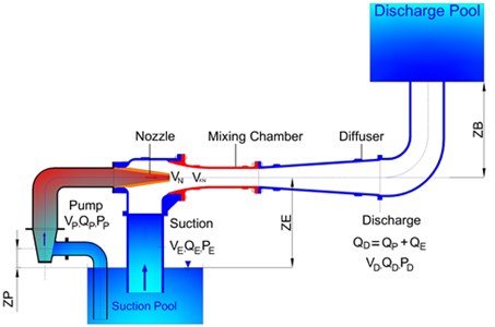
A water jet ejector transfers the water via vacuuming from the desired vessel or system efficiently. It consists of five different parts, which are pump and suction parts, nozzle, mixing chamber and diffuser part as given in Fig. 1. The Pressure energy created from the centrifugal pump is converted into kinetic energy in the nozzle of the water jet ejector. The pressure energy created by the pump is converted into velocity energy at the nozzle. Due to the pressure drop of the fluid coming from the pump, a low-pressure zone is formed between at nozzle outlet and at the mixing chamber inlet. The created low-pressure zone enables vacuuming the fluid and mix with the activated fluid by the pump in the mixing chamber. The mixed liquid is discharged from the system by entering the diffuser part of the ejector where the velocity energy is converted into pressure energy. The basic principle of ejector pumps is based on the momentum transfer at the ejector zones as given in Fig. 1. Ejector theory considers friction, impact and pressure losses which can be used for incompressible and steady state flow.
Ejector suction side energy equation in Eq. (1):
Ejector pump side energy equation in Eq. (2):
Ejector discharge side energy equation in Eq. (3):
Pump and nozzle side energy equation in Eq. (4):
Ejector suction side and nozzle exit energy equation in Eq. (5):
According to the steady state and momentum conservation in Eq. (6):
Energy given by pump to ejector in Eq. (7):
Energy produced at suction side of ejector pump in Eq. (8):
Bernoulli equation can be written according to the Fig. 2 for ejector pump.
Total head for pump side in Eq. (9):
Total head for suction side in Eq. (10):
Total head for discharge side in Eq. (11):
Continuity equations; pump capacity in Eq. (12):
Suction capacity in Eq. (13):
Total area in Eq. (14):
Total capacity in Eq. (15):
Capacity ratio in Eq. (16):
Area ratio in Eq. (17):
In steady state flow conditions, the flow from the nozzle side forces the fluid on the suction side of the ejector to enter the mixing chamber. Head of suction elbow from the suction pool is approximately 3-3.5 m. Vacuum can be calculated in Eq. (18):
where – suction head of ejector, – mean velocity at the ejector suction side (m/s).
Fig. 1A schematic diagram of a Schematic of the water jet ejector system
3. Optimization of design parameters
Multi variable response surface method is used in the optimization study. The basis of the response surfaces methodology is based on the response calculation that occurs depending on number of independent variables () of any physical system. The governing equation of the method is indicated in Eq. (19):
The difference between the observed values and the expected values in any experiment is the fault of the system indicated as in Eq. (20):
In this study, SolidWorks Design of Experiment tool based on Box-Behnken method has been used. Box-Behnken method is an independent quadratic design that does not include full or partial factorial designs. It requires minimal processing. Three levels are needed for each factor. It can be fully or partially rotated. The geometry of the design creates a sphere in the processing range.
In this optimization process, the initial design can be processed through iterative design and development cycles up to the final design. Each design iteration creates new design configuration with a novel set of parameters which change the flow field. The overall dimensions of the water jet ejector are obtained from analytical calculation method which was developed by Wilman [2].
Main design inputs of a water jet ejector are the pump capacity, suction capacity, and pump pressure. Design inputs which are suction and pump capacities of the ejector are made dimensionless in ratio with the pump capacity. Pump pressure is taken as 9 bar due to the requirements of the working conditions for water ejector in the naval ship systems. Design inputs in DoE studies are given in Table 1.
Initial design dimensions are given in Table 2 for each design outputs.
Fig. 2Initial design geometry of a water jet ejector
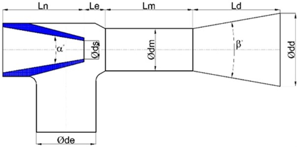
Table 1Design inputs of the initial design
Design input | Symbol | Input value |
Pump capacity | / | 1 |
Suction capacity | / | 2,43 |
Capacity ratio | 2.43 | |
Pump pressure | 8 Bar |
for diameters, for lengths have been used in the dimensionless study. Since nozzle diameter determines the ejector motive capacity, nozzle diameter has been used for determining optimum ejector diameters at a constant pump pressure and flow rate. Additionally, because of the diameter of the mixing chamber is the region where the flow coming from the suction and pump mixes and where the low-pressure zone is formed, the diameter has been used in dimensioning the optimum lengths according to the optimum diameter.
Table 2Dimensionless initial design of the water jet ejector
Design output | Symbol | Dimensionless Unit |
Nozzle diameter | / | 5.71 |
Mixed diameter | / | 3.44 |
Mixed length | / | 1.13 |
Diffuser length | / | 2.27 |
Distance between nozzle and mixing chamber | / | 0.68 |
Nozzle taper angle | 20 | |
Diffuser taper angle | 22 |
3.1. The effects of mixing chamber diameter () and mixing chamber length () on ejector’s suction capacity
Dimensionless design configurations are indicated in Table 3.
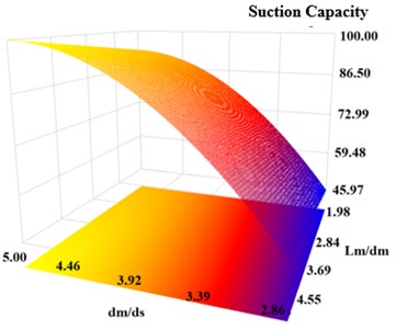
The effects of both dimensionless parameters on suction capacity of the water jet ejector are given in Fig. 3. While the maximum suction capacity is obtained at /= 5, / does not have any effect on the suction capacity of the water jet ejector.
Table 3Basic size and style requirements
Design No. | / | / | Suction capacity (%) |
1 | 5.00 | 4.54 | 100.00 |
2 | 2.85 | 1.98 | 12.79 |
3 | 4.46 | 1.13 | 23.41 |
4 | 5.00 | 3.69 | 92.03 |
5 | 3.92 | 2.84 | 12.70 |
6 | 3.39 | 4.54 | 5.68 |
Fig. 33-D Response surface graphic for dm/ds and Lm/dm
3.2. The effects of suction diameter (), diffuser length () and diffuser outlet diameter on the ejector’s suction capacity
The effect of the suction diameter (), diffuser length () and diffuser outlet diameter () on the ejector’s suction capacity have been examined. Suction diameter () has been made dimensionless in ratio with the mixing chamber diameter () and is defined as /. The diffuser length () has been made dimensionless in ratio with the mixing chamber diameter () and is defined as /. The diffuser outlet diameter () has been made dimensionless in ratio with the mixing chamber diameter () and is defined as /.
Fifteen different design configurations are created by the software for dimensionless parameters as given in Table 4.
Table 4Design configurations and results of de/dm, Ld/dm
Design No. | / | / | / | Suction capacity (%) |
1 | 5.35 | 5.71 | 6.42 | 87.38 |
2 | 5.61 | 6.94 | 7.14 | 89.79 |
3 | 5.10 | 3.88 | 5.71 | 75.84 |
4 | 3.82 | 6.33 | 6.93 | 58.90 |
5 | 4.59 | 8.16 | 5.81 | 62.17 |
6 | 4.84 | 2.65 | 7.04 | 67.37 |
7 | 6.12 | 1.43 | 6.22 | 81.00 |
8 | 4.33 | 2.04 | 6.32 | 60.41 |
9 | 3.57 | 5.10 | 6.12 | 50.67 |
10 | 6.88 | 4.49 | 6.02 | 94.21 |
11 | 5.86 | 10,00 | 6.63 | 93.53 |
12 | 4.08 | 9.39 | 6.53 | 55.26 |
13 | 7.14 | 7.55 | 6.73 | 100.00 |
14 | 6.63 | 3.27 | 6.83 | 89.38 |
15 | 6.37 | 8.78 | 5.91 | 89.20 |
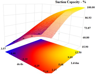
The effects of / and / dimensionless numbers on the ejector suction capacity at different / ratios have been examined. Fig. 4 shows that the increase of / ratio has positive effect on the water jet ejector suction capacity.
As / ratio increases, the ejector suction capacity reaches to maximum value as seen in Fig. 4. Thus, / ratio has a direct effect on the ejector suction capacity. Additionally, the / ratio has minimum direct effect on the ejector suction capacity compared to the / ratio.
Fig. 43-D Response surface graph for de/ds and Ld/dm
The obtained DoE results show that the data of the dimensionless geometrical parameters for the water jet ejector suction capacity can be used to improve the water jet ejector’s suction capacity.
4. 3-D design optimization
The data obtained from the Section 3 are used to improve the water jet ejector in naval ship systems without changing its total length, pump side and discharge side diameters. Initial design of the water jet ejector with overall dimensions is given in Fig. 5.
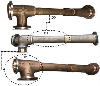
After having the initial design , the first design configuration is named as , and the second design configuration is named as . The geometrical details of the initial design having insufficient suction capacity which is given in Fig. 5. To satisfy naval ship suction capacity requirements, two new water jet ejector designs have been built. As seen in Fig. 3, the maximum suction capacity can be obtained with the ratio of /= 5. Thus, the mixing chamber diameter has been increased from 54 mm to 74 mm in the design .
Although, maximum suction capacity can be obtained with the ratio of / = 7.14 in Table 4, the ratio of de/ds in design has been selected 5.56 because of the system installation dimensions. Thus, the suction diameter has been increased from 72 mm to 100 mm in design.
Design configurations are built by using the SolidWorks software. 3-D water jet ejector design configurations are given in Fig. 6. Numerical analysis of each design configuration has been completed and new patterns of each configuration have been manufactured. The manufactured wooden pattern for configuration is given in Fig. 7.
New design configuration parts have been manufactured by using sand casting method. The ejectors are made of bronze (CuSn10) material due to the sea water working environment. The ejector parts are casted in the company’s foundry. Material composition is prepared by material alloying method in the foundry. After casting, the ejector parts have been machined and assembled. The water jet ejectors completed manufacture are given in Fig. 8.
Fig. 5Design configuration of the water jet ejector
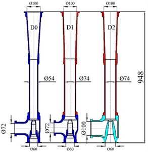
Fig. 63-D design configurations
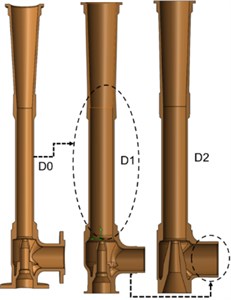
Fig. 7Wooden pattern figures of D1 design
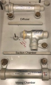
Fig. 8Manufactured bronze water jet ejectors
5. Numerical and experimental analysis
The comparison of numerical, experimental and ‘DoE’ results has been made in the study.
5.1. Numerical study
SolidWorks Flow Simulation software has been used for the numerical analysis of the design configurations. Finite volume discretization method is used in the flow simulation. Pre-process setups are given in Table 5. Hexagonal type grid has been used in the computational flow domains.
Boundary conditions are given in Table 5. The governing equations solved during the flow analysis are continuity, momentum, and viscous terms.
Table 5Flow simulation pre-process set-up.
Analysis dimension | 3-d |
Flow simulation | Steady state |
Fluid type | Water |
Turbulence model | k-ε |
Wall function | Standard |
Wall motion | Stationary |
Grid Type | Hexa |
Number of grids | 2.052.313 |
Pump side, (Static pressure) | 8.0 Bar |
Suction side, (Static pressure) | 0.0 Bar |
Outlet side, (Static pressure) | 0.5 Bar |
Continuity equation in Eq. (21):
momentum equation in Eq. (22):
momentum equation in Eq. (23):
momentum equation in Eq. (24):
Relative velocity vector in Eq. (25):
Viscous terms, shear stress in direction in Eq. (26):
Viscous terms, shear stress in direction in Eq. (27):
Viscous terms, shear stress in direction in Eq. (28):
Pressure, velocity, and viscous terms are computed during the flow analysis.
Numerical analysis has been completed for the suction capacity improvement. The numerical results for the total pressure contour is given in Fig. 9.
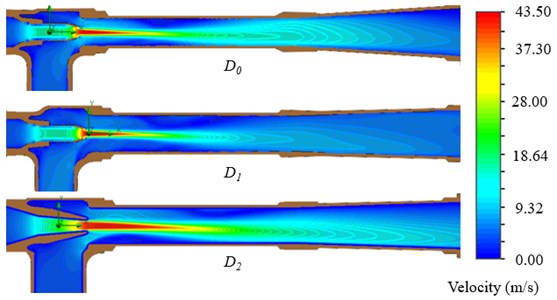
The numerical results for the velocity contours are given in Fig. 10.
5.2. Experimental setup for the ejector pump suction capacity
The suction capacity related experiments of the water jet ejectors have been conducted at the open loop test rig of Gedik Termo Valve Company.
Calibration of the measurement devices were according of international standards. The suction reservoir capacity is 125 m3. Before conducting the test, air is discharged from the suction pool by using a vacuum pump. When the centrifugal pump is filled with the water. The test is started using 3-phase electric motor which works with 50 Hz, 2980 rpm.
Fig. 9Numerical results for total pressure contour
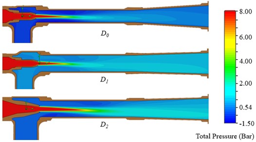
Fig. 10Numerical results for velocity isolines
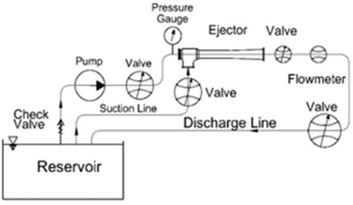
When the centrifugal pump is started, the valve located into suction line is closed, and so pressure at pump outlet and pump flow rate of the ejector are measured. After measuring pump flow rate and pressure, the valve located in suction line is opened. Thus, the total flow rate consisting of pump and suction flow rate capacities are measured from the magnetic flow meter. Suction flow capacity of the ejector pump is calculated by extracting pump flow rate capacity from total flow rate capacity.
The volumetric flow rate capacity is measured using the DN150 mm size of magnetic flowmeters. The water jet ejector test layout is given Fig. 11
Fig. 11Water jet ejector test layout
The ejector test setup is given in Fig. 12.
A list of measurement devices, their accuracy, and maximum uncertainty associated with the calculated quantities are provided in Table 6.
Fig. 12Ejector test setup
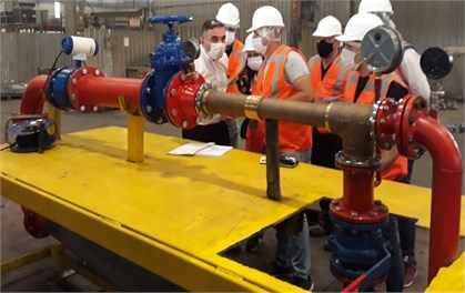
Table 6Uncertainty of the measurement devices
Measured quantity | Equipment | Uncertainty |
(m3/h) | Enelsan, Etrans-M 210K | ± 0.2 % |
(bar) | Pakkens Pressure gauge, 0-16 Bar | ± 0.8 % |
5.3. Comparison of the experimental results with the numerical counterparts
Comparison of numerical and experimental results are given in Table 7. As the results have been compared, deviation between experimental and numerical is very close and deviation is within the tolerance which have been indicated in Lloyd Naval Ship Rules.
Table 7Numerical and experimental results
Parameters | Design | Grid quality | Capacity ratio-X | ||
Coarse | Medium | Fine | |||
Number of the grid | 595890 | 995990 | 2028498 | 1.32 | |
Suction capacity, CFD – m3/h | 56.37 | 54.57 | 52.05 | ||
Suction capacity, experimental – m3 | 52.95 | 52.95 | 52.95 | ||
Number of the grid | 583876 | 1106984 | 2052313 | 1.83 | |
Suction capacity, CFD – m3/h | 67.50 | 75.67 | 74.7 | ||
Suction capacity, experimental – m3 | 73.15 | 73.15 | 73.15 | ||
Number of the grid | 605019 | 1059520 | 2015000 | 2.07 | |
Suction capacity, CFD – m3/h | 108.10 | 96.40 | 104.40 | ||
Suction capacity, Experimental – m3 | 103.40 | 103.40 | 103.40 | ||
5.4. Comparison of the experimental results with the numerical counterparts
The dimensionless ratios obtained from DoE and design applications which are , and are given in Table 8. As / and / increases the capacity ratio increases. Suction and mixing diameters directly affect the suction capacity of the ejector as seen in Table 8.
Table 8Dimensionless parameters comparison table
Dimensionless parameters | DoE | |||
/ | 7.14 | 4.44 | 4.44 | 5.56 |
/ | 6.73 | 5.56 | 5.56 | 5.56 |
/ | 5.00 | 3.00 | 4.11 | 4.11 |
/ | 4.54 | 8.07 | 5.89 | 5.89 |
/ | 7.55 | 6.35 | 4.64 | 4.64 |
Capacity ratio, | 2.43 | 1.32 | 1.82 | 2.07 |
and geometric parameters of the ejector don’t directly have correlation with ejector suction capacity as seen in Table 8 and these both length parameters effect the ejector efficiency.
The higher capacity ratio can be reached by using the DoE data in Table 8 for the next designs.
6. Conclusions
In this study, numerical and experimental analysis have been conducted to improve the suction capacity of the water jet ejector in the naval ship system. Geometrical design parameters affecting the suction capacity of a water jet ejector have been determined by using design of experiment method. Parameters and defined in design of experiment have been used to improve the water jet ejector’s suction capacity. It has been found that and geometrical parameters directly affect the suction capacity of a water jet ejector. When the ratio of / and / increase, ejector capacity ratio increases. Because of the installation dimensions in the system , and have been kept constant. Additionally, it is found that as the ratios of / and / decreases, the flow separation region in the mixing chamber and diffuser of the and have been removed. Therefore, it has positive effect because of the decreasing losses stemming from the flow separation and the friction losses. The suction capacity of the manufactured water jet ejectors increased from 52.95 m3/h to 103.40 m3/h.
References
-
B. M. Tashtoush, M.D. A. Al-Nimr, and M. A. Khasawneh, “A comprehensive review of ejector design, performance, and applications,” Applied Energy, Vol. 240, pp. 138–172, Apr. 2019, https://doi.org/10.1016/j.apenergy.2019.01.185
-
J. T. Wilman, “Jet pumps,” EURATOM, European Atomic Energy Community, 1968.
-
A. A. Sheha, M. Nasr, M. Hosien, and E. Wahba, “Computational and experimental study on the water-jet pump performance,” Journal of Applied Fluid Mechanics, Vol. 11, No. 4, 2018.
-
S. P. Mehta, “A study of water jet pumps,” M.Sc. Thesis, Kansas State University, Manhattan, Kansas, 1968.
-
B. J. Huang, J. M. Chang, C. P. Wang, and V. A. Petrenko, “A 1-D analysis of ejector performance,” International Journal of Refrigeration, Vol. 22, No. 5, pp. 354–364, Aug. 1999, https://doi.org/10.1016/s0140-7007(99)00004-3
-
A. S. Taygankov, “Water jet pump design,” Department of the Navy Naval Intelligence Support Center Translation Division, Washington, 1969.
-
B. Bogi, “Efficient design oriented numerical simulation of an ejector,” M.Sc. Thesis, University of Florida, 2011.
-
T. Benjamin, Ejector Pumps the Calculations. World Pumps Elsevier, 2001.
-
J. Kracik and V. Dvorak, “Development of an analytical method for predicting flow in a supersonic air ejector,” EPJ Web of Conferences, Vol. 114, p. 02059, 2016, https://doi.org/10.1051/epjconf/201611402059
-
M. Falsafioon, Z. Aidoun, and K. Ameur, “Numerical investigation on the effects of internal flow structure on ejector performance,” Journal of Applied Fluid Mechanics, Vol. 12, No. 6, pp. 2003–2015, Jan. 2019.
-
Pierre van Eeden, “A method for prediction of gas/gas ejector performance,” Impiantistica Italiana, Jan. 2013.
-
C. F. Leo, “Analysis of rocket powered ejectors for pumping liquid oxygen and liquid hydrogen,” NASA TN-D 6033, 1970.
-
K. Ameur and Z. Aidoun, “Nozzle displacement effects on two-phase ejector performance: an experimental study,” Journal of Applied Fluid Mechanics, Vol. 11, No. 4, pp. 817–823, Jul. 2018, https://doi.org/10.29252/jafm.11.04.28385
-
Lima Neto and Iran E., “Maximum suction lift of water jet pumps,” Journal of Mechanical Science and Technology, Vol. 25, No. 2, pp. 391–394, Feb. 2011, https://doi.org/10.1007/s12206-010-1221-7
-
K. Aldas and R. Yapici, “Investigation of effects of scale and surface roughness on efficiency of water jet pumps using CFD,” Applied Energy, Vol. 240, pp. 138–172, 2014.
About this article

Authors would like to thank Gedik Termo Vana A. S. for their contribution during the numerical and experimental analysis of the project.
