Abstract
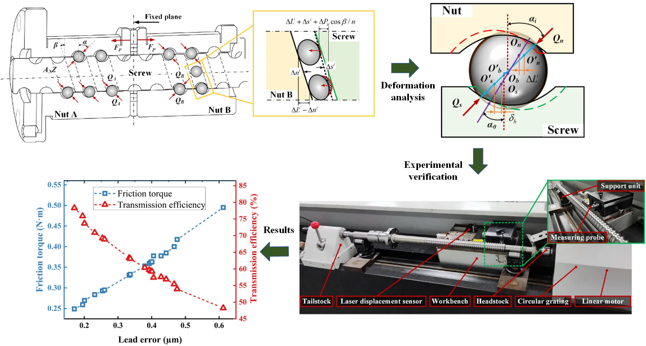
Transmission efficiency is a pivotal indicator, providing a comprehensive view of the overall performance of a ball screw. While extensive research has predominantly focused on computing transmission efficiency across various operating conditions, the factors influencing the variability have often been overlooked. This study introduces an innovative method for computing transmission efficiency, which considers lead error, drawing on deformation coordination theory and load distribution. Multiple ball screws of varying precision grades underwent rigorous testing to quantify lead errors. Subsequently, each screw was matched with an identical set of nuts to measure the respective transmission efficiencies. Experimental results reveal a linear correlation between lead error and transmission efficiency when both lead error and uneven ball load distribution in ball screws are considered. The relative error between the calculated transmission efficiency results and experimental values for ball screws of different precision grades falls within the range of 0 % to 7.42 %, confirming the validity of the proposed model in this paper.
Highlights
- A novel method for calculating transmission efficiency which accounts for lead error is introduced.
- Experimental findings highlight a linear correlation between lead error and transmission efficiency.
- The proposed model is validated through comprehensive testing on ball screws of diverse precision grades.
1. Introduction
Ball screws are extensively utilized in high-precision machinery, 3D printing, and industrial robots due to the remarkable attributes, including high accuracy, low friction, and exceptional transmission efficiency. Transmission efficiency, denoting the ratio of input to output power, typically expressed as a percentage, holds paramount importance in ball screws, particularly in applications requiring precise positioning and the transfer of substantial torque [1]. Efficient ball screw systems not only curtail energy consumption and minimize heat generation but also elevate the overall system performance. Friction torque emerges as a primary source of energy dissipation within ball screws, where a higher friction torque corresponds to lower transmission efficiency [2]. Hence, the reduction of friction torque is imperative for augmenting transmission efficiency. In ball screws, friction torque predominantly originates from the interaction between the balls and the raceway. Concurrently, the lead error persists within ball screws, signifying the variance between actual and theoretical displacement [3]. This factor plays a critical role in upholding the accuracy and dependability of the ball screw system. To comprehensively assess the forces acting on each ball in a ball screw, an analysis of load distribution is essential.
Xu et al. [4] developed a systematic analysis model for calculating ball screw friction torque through creep analysis and force balance principles. Based on the equilibrium of the forces and moments acting on the ball. Olaru et al. [5] proposed a novel friction model to estimate friction losses. Oh et al. [6] formulated an explicit friction torque model considering both the applied load and viscous friction terms. Zhang et al. [7] provided insights into the differences between the ball-screw and ball-nut interfaces regarding lubrication and friction. They made a transient mixed lubrication model for grease-lubricated ball screw mechanisms. It is worth noting that all of the previously mentioned research assumes uniform ball loading and omits consideration of the influence of the lead error on friction torque calculation.
To holistically evaluate the forces affecting individual balls within a ball screw, analyzing load distribution is imperative. Mei et al. [8] delved into load distribution in ball screws, particularly emphasizing the effects of negative and positive geometric errors on ball loads. Employing experimental techniques like photoelasticity and mark-tracking methods, Bertolaso et al. [9] determined load distribution in ball screw systems. Liu et al. [10] introduced a novel method for analyzing static load distribution in ball screws, accounting for nut position variations and streamlining the analysis via a transformed coordinate system. Lin et al. [11] presented a low-order static load distribution model for ball screws, considering lateral deformations and geometric errors, which provided accurate predictions while demanding reduced computational resources. Nevertheless, previous studies on load distribution overlooked the impact of lead error and variations in contact angles due to ball deformation and applied loads. Moreover, these studies lacked experimental validation.
This paper investigates the impact of lead error on the load distribution in ball screws and establishes a correlation between lead error and friction torque, culminating in the developing of a transmission efficiency calculation model. Experimental verification is undertaken to measure lead error in screws of various precision grades, and the respective transmission efficiency of the ball screw is evaluated.
2. Theoretical analysis
2.1. Load distribution model considering lead error
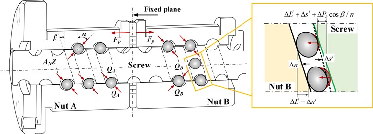
Lead error, representing the disparity between the actual pitch and the designated or theoretical value, can be attributed to various factors, including manufacturing imperfections, assembly inaccuracies, material characteristics, friction, and environmental variables. These discrepancies can lead to deviations in the positioning and movement of the ball screw, consequently diminishing the precision and overall performance. To counteract axis elongation due to temperature fluctuations or applied loads during operation, it is typical to keep the lead error below 0. Fig. 1 illustrates contact analysis of a double-nut ball screw subjected to preload, revealing a two-point contact configuration between each ball and the raceway, achieved by inserting a spacer between the nuts to generate preload. The -th contact unit pertains to the contact regions between the screw, nut, and balls between the (-1)th and the -th balls. By considering the coordinate deformations among the nut, screw, and balls, the following equation can be derived:
where the subscript , denote the screw and nut, respectively, and the superscript denotes the -th unit. denotes the amount of axial deformation, denotes the lead error, denotes the lead angle, denotes the count of active balls within a single raceway circuit. denotes the axial elongation, which can be written as follows:
where denotes the helical pitch, which refers to the axial distance that a ball screw advances with a single complete revolution.
The -th axial deformations of the screw and nut, represented as and , can be expressed as follows [8]:
where denotes Young’s elastic modulus, denotes the cross-sectional area, and denotes the axial force of the -th unit, which can be written as [10]:
Fig. 1Contact analysis between the ball and the raceway
The total axial force can be written as the sum of each ball with normal force applied [12]:
where denotes the contact angle. , denotes the stiffness coefficient, denotes the material constant, and denotes the normal deformation of the balls.
Following the simplification of Eq. (1), the following expression can be obtained:
By combining Eq. (3), Eq. (5) and Eq. (6), the axial force can be re-written as:
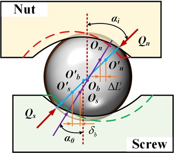
Fig. 2 exhibits the contact deformation analysis diagram of the -th ball. The relationship between the normal deformation and the contact angle of the -th unit can be analyzed and written as follows:
where the and denotes the radius curvature of the screw and nut, respectively, denotes the ball radius.
In Section 3, simulation results and accompanying discussions regarding the total axial deformation of the balls and the total axial deformation of the nut and screw are provided. The calculation results indicate a significant disparity between the sum of axial deformations in the nut and screw compared to the sum of axial deformations in the balls. Consequently, when calculating the axial deformation of each loaded ball, the deformation in the nut and screw can be safely disregarded. In this context, the axial deformation can be represented as a linear function by merely computing the axial deformation of the first ball and considering the geometric relationships between each ball:
Fig. 2Deformation analysis of the i-th ball
2.2. The transmission efficiency calculation model
The transmission efficiency calculation model can be given as [13]:
where denotes the linear velocity of the nut, denotes the screw rotation speed, , and denotes the term of viscous friction torque due to lubrication condition [6]. denotes the friction torque generated by the supported bearings [14]. Based on the friction torque model proposed in Ref [15], the friction torque due to the axial load can be written as:
where denotes the total number of the balls, denotes the friction coefficient, denotes the radius of the screw.
It is worth emphasizing that the introducing of an axial load to the ball screw alters the dynamics of the interaction between the balls and the raceway, akin to the impact of preload. Both preload and axial load affect the contact conditions between the balls and the raceway, leading to changes in the ball-to-raceway interaction [15]. In this research, the preload, which is preconfigured with a gasket before testing, is regarded as equivalent to the axial load without an external load. Thus, the preload is considered as the axial load and can be expressed as follows:
Moreover, Eq. (11) can be re-written as:
Then, the normal deformation of the ball and the associated contact alteration resulting from the applied axial offset of the preload can be expressed as follows:
If the average value of lead error for the circles is defined as (), the lead error for a single circle can be expressed as . The lead error for each individual ball can be described as , where . Consequently, the spacing between each ball can be represented as . Building on Eq (9), when the deformation of the first ball is assumed to be , the distance of the -th ball to the screw axial can be expressed as follows:
The axial deformation of the -th ball can be written as:
The normal deformation and the contact angle can be written as:
Similarly, when :
3. Experimental verification
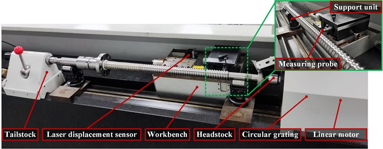
The specifications of the tested ball screws are presented in Table 1. The experimental verification necessitates the utilization of lead error measuring equipment and transmission efficiency equipment. The lead error measuring equipment, depicted in Fig. 3, encompasses several crucial components: a linear motor, a headstock, a workbench, a circular grating, a laser displacement sensor, a measuring probe, a support unit, and a tailstock. An air float system is employed to minimize friction during workbench movement, and the test precision is enhanced by using a laser displacement sensor. The measurement setup for the screw entails a linear motor to drive the ball screw. A measuring probe connected to the workbench uses the screw raceway to enable axial movement. A laser displacement sensor is integrated into the measurement equipment to capture axial displacement, with a circular grating affixed to the motor for measuring rotation angles, facilitating the calculation of theoretical displacement. The variance between the actual axial displacement and the theoretical axial displacement constitutes the lead error. In this evaluation, the lead errors for screws of various precision grades were measured without the installation of nuts. Following this, each screw was combined with an identical set of nuts, gaskets, and balls to create an assembled ball screw system, incorporating varying levels of preload generation. Subsequently, the transmission efficiency values of each ball screw were determined using the transmission efficiency equipment, as described in Ref [16].
Table 1Specification of the ball screw
Parameters | Value | Unit |
Curvature radius of nut | 3.304 | mm |
Curvature radius of screw | 3.304 | mm |
Nominal diameter | 16 | mm |
Helix pitch | 10 | mm |
Ball diameter | 6.35 | mm |
Number of balls | 60 | / |
Contact angle | 45 | degree |
Young’s modulus | 210 | Gpa |
Poisson’s ratio | 0.3 | / |
Friction coefficient | 0.003 | / |
Working environment | 20 | ℃ |
Fig. 3The lead error measuring equipment
4. Results and discussion
Fig. 4 illustrates the theoretical results of the contact angle and the normal force variation as lead error increases across different precision grades. Following GB/T 17587.3-2017 [17], the precision of ball screws gradually decreases from P1 to P5. In the case of P5, the effective distance of the ball screw ranges between 550-630 mm, leading to a corresponding lead error fluctuating within the range of approximately ±32 μm. For that, the lead error in each raceway is around ±0.5 μm. Consequently, the lead error for accuracy grades from P4 to P1 can be specified as ±0.4, ±0.3, ±0.2, ±0.1, respectively. As a result, the lead error should be considered within the range –0.5 μm to +0.5 μm. It is evident that the lead error significantly affects the uniformity of the contact angles and the load distribution of the normal force. When the lead error , the gap between the screw-raceway and the nut-raceway decreases, causing ball compression. As the number of balls accumulates, the offset between the screw and nut raceways increases, resulting in greater ball and raceway extrusion deformation, leading to an upward trend in load distribution. Conversely, when , the deformation scenario is reversed, with a more significant gap between the screw and nut raceway, leading to a downward trend in load distribution.
Fig. 4Theoretical results of contact angle and normal force variation
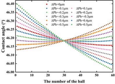
a) The contact angle distribution
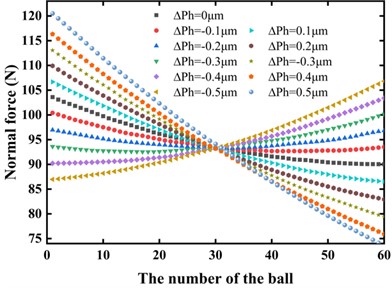
b) The normal force distribution
Table 2 compares the theoretical results of the total axial contact deformation of the balls, denoted as , and the sum of the deformations in the screw-and-nut, which is expressed as . The cumulative elastic deformation of the screw-and-nut is significantly smaller than that of the balls, comprising only 0.1490 % to 0.1677 % of the total deformation. Consequently, when analyzing load distribution among the balls, it is reasonable to disregard the axial deformation of the nut and the screw.
Table 2Theoretical results of the axial contact deformation comparison
/ μm | / μm | ) / μm |
–0.5 | 432.3171 | 0.7250 |
–0.4 | 433.0140 | 0.7146 |
–0.3 | 432.5310 | 0.7071 |
–0.2 | 432.0105 | 0.6995 |
–0.1 | 432.7167 | 0.6887 |
0 | 432.2016 | 0.6809 |
0.1 | 431.6891 | 0.6730 |
0.2 | 431.3219 | 0.6650 |
0.3 | 430.7114 | 0.6569 |
0.4 | 430.2062 | 0.6486 |
0.5 | 429.7035 | 0.6403 |
Fig. 5 illustrates the correlation between transmission efficiency and lead error, comparing the model presented in this paper with Wei's [2]. The model introduced in this study aligns more closely with the experimental results, whereas Wei’s model exhibits a more significant disparity. As the lead error increases, the transmission efficiency experiences a decrease. Wei’s model yields a transmission efficiency error range of 10.92 % to 63.85 %, while the relative error range of the transmission efficiency calculated using the model in this paper falls within 0 % to 7.42 %. This observation highlights the substantial errors that arise when neglecting variations in contact angles due to ball deformation and the assumption of uniform force applied to each ball.
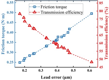
Fig. 6 shows the relationship between the transmission efficiency and the friction torque with lead error increase. As the lead error gradually increases, the friction torque exhibits an upward trend. This is due to a lead error causing uneven load distribution within the ball screw, resulting in increased friction. Conversely, as the lead error increases, the transmission efficiency gradually decreases. Lead error leads to system instability in the ball screw, increasing energy losses, reflected by a gradual decline in transmission efficiency on the graph. These trends illustrate the significant impact of lead error on ball screw performance. Also, the position of the crossover point of the transmission efficiency and the friction torque can guide engineers in selecting appropriate design parameters to achieve the desired friction and transmission efficiency, facilitating the optimization of the ball screw system design.
Fig. 5Model comparison with experimental results
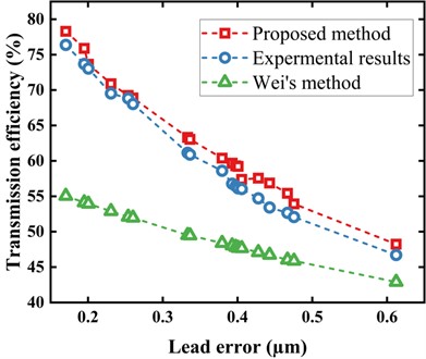
Fig. 6Relationship between the friction torque and the transmission efficiency
5. Conclusions
A comprehensive efficiency model has been developed to analyze ball screws, considering lead error. This research underscores the substantial influence of lead error on ball screw performance. The presence of lead error results in non-uniform contact angles between balls and raceways, leading to uneven load distribution, which, in turn, contributes to increased friction torque and transmission efficiency decreases.
With the increase in lead error, the friction torque and transmission efficiency exhibit significant variations. Hence, it is imperative to consider and control lead error when designing and utilizing ball screw systems. This study highlights the critical role of maintaining low lead error to maximize ball screw efficiency.
In summary, this research provides crucial insights into the effects of lead error on ball screw performance, underscoring the importance of lead error management for achieving optimal system performance and efficiency.
References
-
D. Mundo and H. S. Yan, “Kinematic optimization of ball-screw transmission mechanisms,” Mechanism and Machine Theory, Vol. 42, No. 1, pp. 34–47, Jan. 2007, https://doi.org/10.1016/j.mechmachtheory.2006.02.002
-
C.-C. Wei and R.-S. Lai, “Kinematical analyses and transmission efficiency of a preloaded ball screw operating at high rotational speeds,” Mechanism and Machine Theory, Vol. 46, No. 7, pp. 880–898, Jul. 2011, https://doi.org/10.1016/j.mechmachtheory.2011.02.009
-
K. Wang, C.-G. Zhou, Y. Ou, and H.-T. Feng, “Investigation of the transmission accuracy of ball screw considering errors and preloading level,” The International Journal of Advanced Manufacturing Technology, Vol. 118, No. 11-12, pp. 3917–3932, Feb. 2022, https://doi.org/10.1007/s00170-021-08088-x
-
N. Xu, W. Tang, Y. Chen, D. Bao, and Y. Guo, “Modeling analysis and experimental study for the friction of a ball screw,” Mechanism and Machine Theory, Vol. 87, pp. 57–69, May 2015, https://doi.org/10.1016/j.mechmachtheory.2014.12.019
-
D. Olaru et al., “A new model to estimate friction torque in a ball screw system,” in Product engineering: eco-design, technologies and green energy, 2005, pp. 333–346, https://doi.org/10.1007/1-4020-2933-0_20
-
K.-J. Oh, L. Cao, and S.-C. Chung, “Explicit modeling and investigation of friction torques in double-nut ball screws for the precision design of ball screw feed drives,” Tribology International, Vol. 141, p. 105841, Jan. 2020, https://doi.org/10.1016/j.triboint.2019.105841
-
Y. Zhang, P. Cui, J. Yang, Z. Wang, and W. Pu, “Dynamic grease lubrication and friction behavior of ball screw mechanism in high-frequency reciprocating motion,” Tribology International, Vol. 178, p. 108068, Feb. 2023, https://doi.org/10.1016/j.triboint.2022.108068
-
X. Mei, M. Tsutsumi, T. Tao, and N. Sun, “Study on the load distribution of ball screws with errors,” Mechanism and Machine Theory, Vol. 38, No. 11, pp. 1257–1269, Nov. 2003, https://doi.org/10.1016/s0094-114x(03)00070-3
-
R. Bertolaso, M. Cheikh, Y. Barranger, J.-C. Dupré, A. Germaneau, and P. Doumalin, “Experimental and numerical study of the load distribution in a ball-screw system,” Journal of Mechanical Science and Technology, Vol. 28, No. 4, pp. 1411–1420, Apr. 2014, https://doi.org/10.1007/s12206-014-0128-0
-
C. Liu, C. Zhao, X. Meng, and B. Wen, “Static load distribution analysis of ball screws with nut position variation,” Mechanism and Machine Theory, Vol. 151, p. 103893, Sep. 2020, https://doi.org/10.1016/j.mechmachtheory.2020.103893
-
B. Lin, C. E. Okwudire, and J. S. Wou, “Low order static load distribution model for ball screw mechanisms including effects of lateral deformation and geometric errors,” Journal of Mechanical Design, Vol. 140, No. 2, Feb. 2018, https://doi.org/10.1115/1.4038071
-
H.-X. Zhou, C.-G. Zhou, H.-T. Feng, and Y. Ou, “Theoretical and experimental analysis of the preload degradation of double-nut ball screws,” Precision Engineering, Vol. 65, pp. 72–90, Sep. 2020, https://doi.org/10.1016/j.precisioneng.2020.04.012
-
M. C. Lin, S. A. Velinsky, and B. Ravani, “Design of the ball screw mechanism for optimal efficiency,” Journal of Mechanical Design, Vol. 116, No. 3, pp. 856–861, Sep. 1994, https://doi.org/10.1115/1.2919460
-
K. Yokoyama, A. Tohyama, and T. Suzuki, “Evaluation of friction torque of rolling bearing,” Journal of the Japan Society for Precision Engineering, Vol. 62, No. 2, pp. 210–214, 1996.
-
C.-G. Zhou, H.-T. Feng, Z.-T. Chen, and Y. Ou, “Correlation between preload and no-load drag torque of ball screws,” International Journal of Machine Tools and Manufacture, Vol. 102, pp. 35–40, Mar. 2016, https://doi.org/10.1016/j.ijmachtools.2015.11.010
-
Y. Zhang et al., “An analysis method for the transmission efficiency of the preloaded ball screw based on wear volume calculation,” Proceedings of the Institution of Mechanical Engineers, Part J: Journal of Engineering Tribology, Vol. 236, No. 12, pp. 2392–2405, 2022.
-
“GB/T 17587.3-2017: Rolling Bearings – Radial Bearings – Part 3: Needle Roller Bearings,” 2017.
Cited by
About this article

This project is supported by the National Natural Science Foundation of China (Grant No. 51905274), the National Science and Technology Major Projects of China (Grant No. TC210H038-02), the Open Fund of Key Laboratory of CNC Equipment Reliability of Jilin University (Grant No. 202105).
The datasets generated during and/or analyzed during the current study are available from the corresponding author on reasonable request.
Yishen Zhang conceived the study, developed the research methodology, and authored the manuscript. Changguang Zhou provided supervision and conducted a thorough review of the manuscript. Hutian Feng also contributed to the manuscript review. All authors have read and approved the final manuscript.
The authors declare that they have no conflict of interest.
