Abstract
The control effectiveness of the all-electric tank stabilizers directly affects the firing accuracy of the tank gun. In order to improve the firing accuracy of the moving tank, this paper proposes a sliding mode control (SMC) strategy using neural network feed-forward compensation for the tank bidirectional stabilizers. SMC technology can quickly and effectively deal with uncertainties, unmodeled terms, and external disturbances in complex tank systems. Neural networks possess the advantage of approximating arbitrary continuous functions in finite time, realizing the estimation of SMC control errors with feed-forward compensation. The Lyapunov stability analysis proves that the designed controller can achieve asymptotic stabilization in finite time. Finally, both co-simulation and physical experiments are conducted. The results show that the proposed control strategy possesses better tracking speed and tracking accuracy compared to the conventional controller and exhibits strong robustness.
Highlights
- In this paper, a sliding mode control strategy using neural network feed-forward compensation is designed for an all-tank bidirectional stabilizers.
- The strategy naturally combines the sliding mode control technology and neural network technology together.
- The self-learning ability of neural network is utilized to estimate and compensate the control error in sliding mode control.
1. Introduction
Tanks have the advantages of high destructive power, high mobility, and high protection. Tank stabilizer is the core component to realize that the tank can strike accurately. It directly affects the stabilizing accuracy and striking effect of the tank gun. The main actuator of the stabilizer of the new generation all-electric tank is servo motor. It offers the characteristics of faster response and smaller size than traditional electro-hydraulic actuator [1]. Disturbances to the actuator from external excitations, unmodeled terms in the controller, all of these will change compared to electrohydraulic actuators. Scholars have done a lot of research on how to design a new tank stabilizer for complex tank systems to improve firing accuracy [2].
Gao [3] proposes a self-resistant control strategy based on neural network algorithm and self-resistant algorithm for the electric control servo system of a tank in vertical direction. However, the model built by Gao cannot reflect the complex backlash and transmission relationship between the whole tanks. Chen [4] targeted the electro-hydraulic servo system of the tank in the vertical direction, modeled the hydraulic servo system using AMESim software, and modeled the multibody dynamics of the whole tank using Recurdyn software. This type of validation provides a brilliant idea for our research. Nevertheless, Co-simulation results alone cannot be used as valid evidence to validate the algorithm. Sliding Mode Control (SMC) has been gradually applied to the control of permanent magnet synchronous motors (PMSMs) due to its insensitivity to external perturbations and parameter uptake, fast response time, high robustness, and low requirement of model accuracy [5].
Ma [6] proposed a neural network-based compensation scheme for the shortcomings of adaptive control, which can adapt and adjust the neural network weights online. Based on this, this paper has a bold idea to model a bidirectional stabilizers for a complex tank gun system. The sliding mode control is used to deal with the uncertainties of the system, and the neural network is used to approximate the control error.
Inspired by the above researches, a sliding mode control strategy based on neural network compensation is proposed in this paper. The proposed SMC controller is designed with exponential convergence rate, which can suppress the system jitter well and achieve fast convergence. This contributes significantly to the handling of uncertainties in the system. Using the property that neural networks can approximate any continuous function in finite time, neural network estimation of SMC control error with feedforward compensation is realized. The Lyapunov stability analysis proves that the proposed controller can achieve asymptotic stability in finite time.
The sections of this paper are organized as follows. In the second part, the spatial dynamics equation for the tank bidirectional stabilizers considering electromechanical coupling is established. Then the SMC controller is proposed and a neural network is designed for compensating the control error of SMC. The Lyapunov stability analysis of the proposed controller is given. In the third part, co-simulation verification is carried out. In the fourth part, experimental validation is carried out. In the fifth part, the conclusion is presented.
2. Model building and controller design
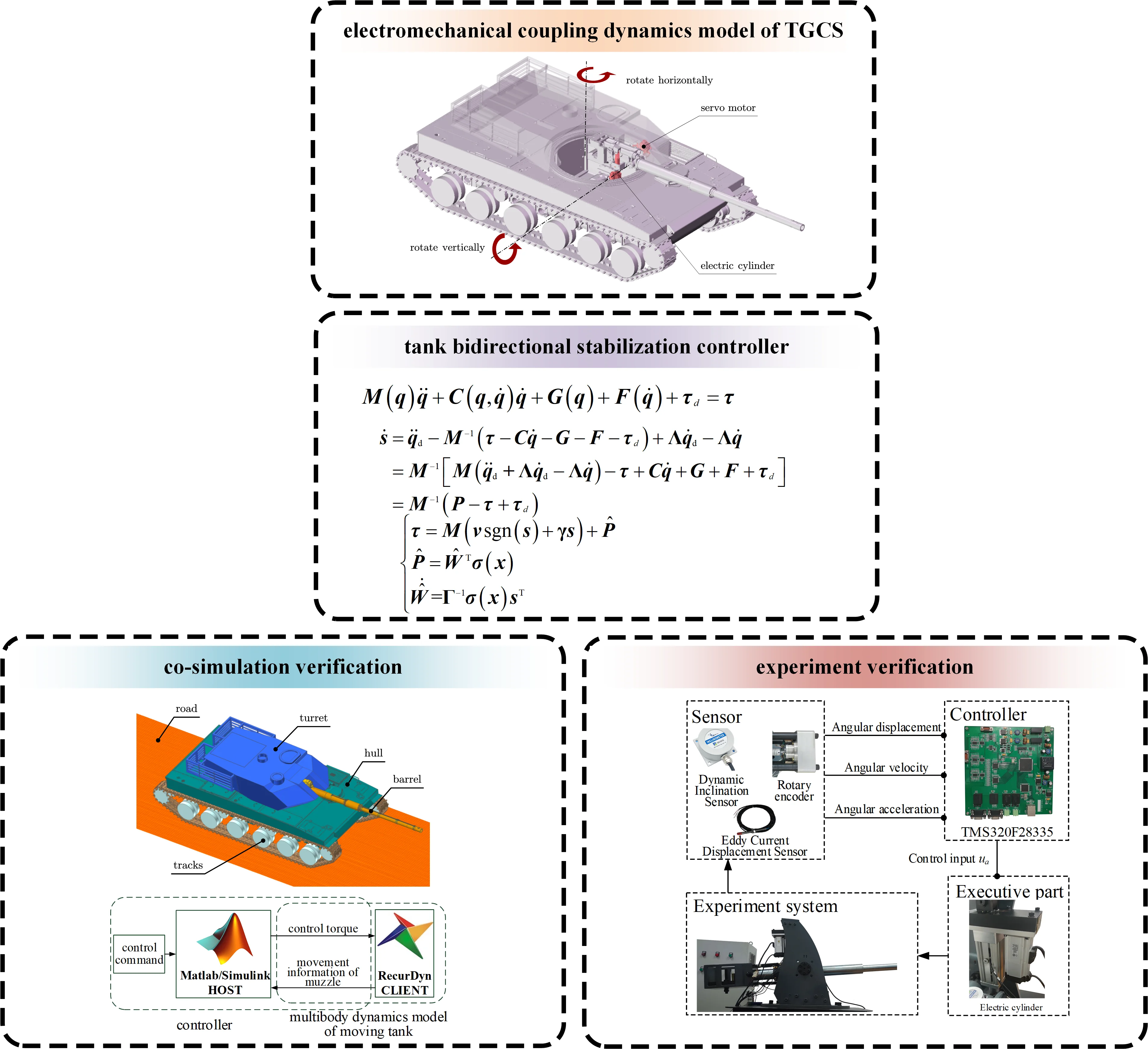
2.1. Electromechanical coupled dynamics modeling
Fig. 1Principle of bidirectional movement of an all-electric tank
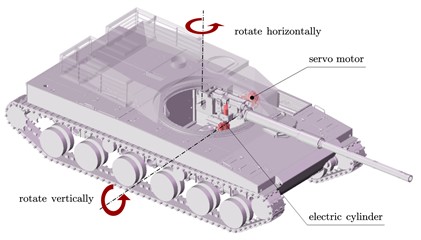
Stabilizers for all-electric tanks include horizontal stabilizer and vertical stabilizer. In the horizontal direction, the actuator is a servo motor driving the turret in the horizontal direction via a reducer. In the vertical direction, the actuator is an electric cylinder. The extension and retraction of the electric cylinder can be realized by controlling the servo motor in the electric cylinder, thus accomplishing the rotational movement of the barrel around the trunnion [7]. As a result, the dynamical equation for the bidirectional stabilizers on an all-electric tank is established as:
where , , represent muzzle angular displacement, angular velocity, and angular acceleration, respectively. is the inertia matrix. Consider the definition of , it is a positive definite matrix. and is the Koch force matrix. is the gravity matrix. is the friction matrix. is all unmodeled error and system disturbance. is the control torque. They are defined as follows:
where the parameters involved are defined as:
For ease of description, subscript denotes the parameters associated with the tank in the horizontal direction and subscript denotes the parameters associated with the tank in the vertical direction. denotes the angular displacement of the muzzle, denotes the mass of the rotating part, denotes the distance from the center of mass of the rotating body to the center of rotation, and denotes all unmodeled errors and systematic disturbances, where .
2.2. SMC controller design
Define the tracking angular displacement error , and the angular velocity tracking error as:
the desired value of , and is the desired value of .
Define the sliding mode function as:
where is the sliding mode vector function. is the designed diagonal matrix and all of its diagonal elements are greater than zero.
The dynamic properties of the sliding mode control strategy require the system to converge to an equilibrium state when stability is obtained, i.e., . Therefore, the goal now is to ensure that when the system equilibrium point is reached, there is . Combining Eqs. (2) and (3) and taking the derivative for yields:
Bringing Eq. (1) into (4) yields:
where .
Let , the control torque can be obtained as:
In this paper, sliding mode control based on exponential convergence law is selected as:
where is the sliding mode robust term, and is a matrix that has all diagonal elements greater than 0.
Combining Eqs. (5) and (7), one gets:
where is the robust term.
2.3. Design of neural network compensation
Define the generalized state of as , and introduce the neural network as follows:
where is the activation function, is the neural network input, is the neural network weight function, is the estimate of , is the estimate of , and is the neural network approximation error.
In order to make the weight error move in the direction of negative gradient, this paper defines the neural network adaptive rate as:
where is a diagonal matrix with diagonal elements greater than 0, one of the design variables of the algorithm.
Combining Eqs. (8) and (9), the controller is obtained:
2.4. Stability analysis
Define the Lyapunov function as:
Taking the derivative of gives:
Therefore, the robust term is designed as , where and are design parameters. Choosing the right and means that can be guaranteed.
Due to the positive definite character of the inertia matrix , it is clear that there is as . Therefore, the controller proposed in this paper can achieve asymptotic stabilization.
The final controller designed in this paper is:
3. Co-simulation validation
3.1. Principle of co-simulation
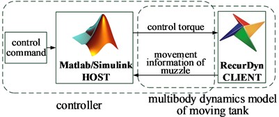
The actual tank structure is quite complex, this paper only considers the fire system and chassis system of the tank. The multibody dynamics model of the real tank is established by the software Recurdyn, as shown in Fig. 2. The 3D model of E-level road surface is built according to the literature [8], and it is imported into the Recurdyn software. The controller is written in Matlab/Simulink. The software interface is utilized to realize the real-time data transmission of the two software. The principle of co-simulation is shown in Fig. 3.
3.2. Parameter selection
The relevant dynamical parameters involved are set with 5200.00 kg, 2088.15 kg, 1.05 m, 5.12 m. In addition, the acceleration of gravity 9.80 m⋅s-2.
The neural network input is selected as , and the neural network activation function is selected as Gaussian function:
where denotes the -th node in the hidden layer. is the center point of the Gaussian function, designed as = [–3, –2, –1, 0, 1, 2, 3]. is the width of the Gaussian function, designed as 8.
In addition, other design parameters are selected as , , , 10.
To validate the superiority of the proposed controller, conventional PID controller is selected for comparison. PID is widely used in tank stabilizers, which are mainly adjusted by , , three parameters. For the co-simulation, 1200, 800, 35, 900, 600, 17 are chosen.
The muzzle motion command is set to a step function of:
Fig. 2Multibody dynamics model built in Recurdyn
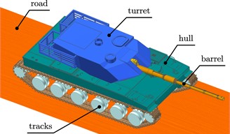
Fig. 3Schematic diagram of co-simulation
4. Results
4.1. Tracking performance analysis
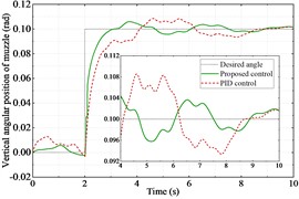
The co-simulation is successfully implemented. Fig. 4(a) and Fig. 5(a) show the angular displacements of the muzzle. Fig. 4(b) and Fig. 5(b) show their errors. It can be clearly seen that the proposed controller has a better control effect compared to the PID controller. The proposed controller spends 1.45 seconds to reach stabilization, while the PID controller spends 1.98 seconds, an improvement of 26.8 %. Fig. 4(c) and Fig. 5(c) show the motor output torque with two controllers. The motor torque output reaches its maximum value at the instant the step command is received by the tank bidirectional stabilizer. Comparing the maximum value of torque of the two controllers, the proposed controller reduces the maximum value of torque by 8.6 % in the horizontal direction and 44.3 % in the vertical direction than the PID controller.
4.2. Anti-interference performance analysis
The anti-jamming performance analysis is realized by the experiment of fixed angle commands. The experiment is to keep the tank gun at a 0 degree pointing angle both horizontally and vertically, with different controllers. In order to observe the effects of uncertainty, to external excitation and noise on the deliberative controller, we compare the tank driving at 20 km/h and 30 km/h on D-level and E-level roads. In order to quantify the effectiveness of the controller, the absolute average error within a finite period of time is commonly employed to characterize tank gun stability accuracy. The expression is:
where is the total number of sampling points and is the angular position error at . The results of the above experiments are calculated and analyzed ranging from 6 to 10 s. Their comparison pairs with PID controllers are shown in Fig. 6.
Fig. 4Performance of the tank stabilizer in the horizontal direction
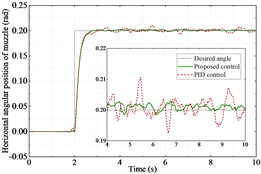
a) Angular displacement
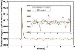
b) Angular displacement error
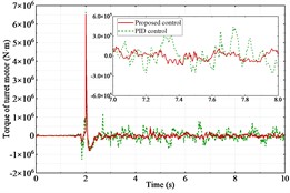
c) Output torque
Fig. 5Performance of the tank stabilizer in the vertical direction
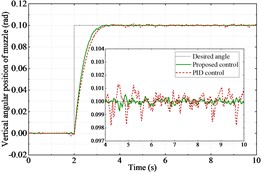
a) Angular displacement
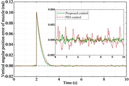
b) Angular displacement error
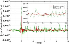
c) Output torque
Fig. 6Tank gun stability accuracy against different excitation
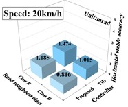
a) Horizontal accuracy at speeds of 20 km/h
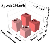
b) Vertical accuracy at speeds of 20 km/h
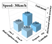
c) Horizontal accuracy at speeds of 30 km/h
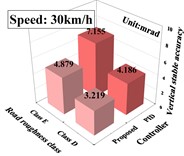
d) Vertical accuracy at speeds of 30 km/h
5. Experimental validation
According to the actual tank gun, a semi-physical experimental platform for the tank was built based on the DSP chip. The overall scheme is shown in Fig. 7. The roadway excitation data in the semi-physical simulation platform is derived from the real moving tank measurement data and scaled down equally according to the scale of the experimental platform. The remaining parameters are the same as in the co-simulation. Figs. 8 and 9 illustrate the horizontal and vertical angular displacements. Similarly, it can be seen that the proposed control strategy is much more effective than the PID controller.
6. Conclusions
In this paper, a sliding mode control strategy using neural network feed-forward compensation is designed for an all-tank bidirectional stabilizers. The strategy naturally combines the sliding mode control technology and neural network technology together. The self-learning ability of neural network is utilized to estimate and compensate the control error in sliding mode control. It can be used in enabling the tank to complete the pointing mission quickly and accurately, thus improving the firing accuracy of the moving tanks. Experiments show that the proposed controller has better robustness and anti-interference ability compared with the PID controller. Meanwhile, this paper provides a new way to solve the uncertainties of complex nonlinear systems. The study can extend this controller to other nonlinear models.
Fig. 7Semi-physical simulation platform experiment
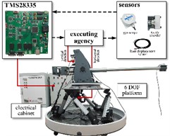
Fig. 8Horizontal angular displacement
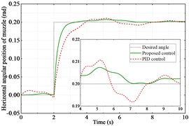
Fig. 9Vertical angular displacement
References
-
T. Dursun, F. Büyükcivelek, and Utlu, “A review on the gun barrel vibrations and control for a main battle tank,” Defence Technology, Vol. 13, No. 5, pp. 353–359, Oct. 2017, https://doi.org/10.1016/j.dt.2017.05.010
-
H. Zheng, X. Rui, J. Zhang, S. Zhang, and J. Gu, “Improved modeling and active disturbance rejection control of tank gun control system,” Proceedings of the Institution of Mechanical Engineers, Part I: Journal of Systems and Control Engineering, Vol. 236, No. 9, pp. 1649–1666, Jun. 2022, https://doi.org/10.1177/09596518221104532
-
Q. Gao, Z. Sun, G. Yang, R. Hou, L. Wang, and Y. Hou, “A novel active disturbance rejection-based control strategy for a gun control system,” Journal of Mechanical Science and Technology, Vol. 26, No. 12, pp. 4141–4148, Jan. 2013, https://doi.org/10.1007/s12206-012-0879-4
-
Y. Chen and G. Yang, “Dynamic simulation of tank stabilizer based on adaptive control,” Proceedings of the Institution of Mechanical Engineers, Part C: Journal of Mechanical Engineering Science, Vol. 233, No. 9, pp. 3038–3049, Sep. 2018, https://doi.org/10.1177/0954406218802315
-
Z. Zhou, C. Xia, Y. Yan, Z. Wang, and T. Shi, “Torque ripple minimization of predictive torque control for PMSM with extended control set,” IEEE Transactions on Industrial Electronics, Vol. 64, No. 9, pp. 6930–6939, Sep. 2017, https://doi.org/10.1109/tie.2017.2686320
-
X. Ma, W. X. Deng, S. S. Yuan, J. Y. Yao, and G. L. Yang, “Neural network based adaptive rise control of tank gun systems,” in Journal of Physics: Conference Series, Vol. 1507, No. 5, p. 052001, Apr. 2020, https://doi.org/10.1088/1742-6596/1507/5/052001
-
Y. Wang, S. Yuan, Q. Sun, X. Wang, and G. Yang, “Adaptive robust stability control of all-electrical tank gun compensated by radial basis neural network,” IEEE Access, Vol. 11, pp. 115968–115985, Jan. 2023, https://doi.org/10.1109/access.2023.3325339
-
Y. Ma, G. Yang, Q. Sun, X. Wang, and Q. Sun, “Adaptive robust control for tank stability: a constraint-following approach,” Proceedings of the Institution of Mechanical Engineers, Part I: Journal of Systems and Control Engineering, Vol. 235, No. 1, pp. 3–14, Jul. 2020, https://doi.org/10.1177/0959651820937847
About this article

The authors have not disclosed any funding.
The datasets generated during and/or analyzed during the current study are available from the corresponding author on reasonable request.
The authors declare that they have no conflict of interest.
