Abstract
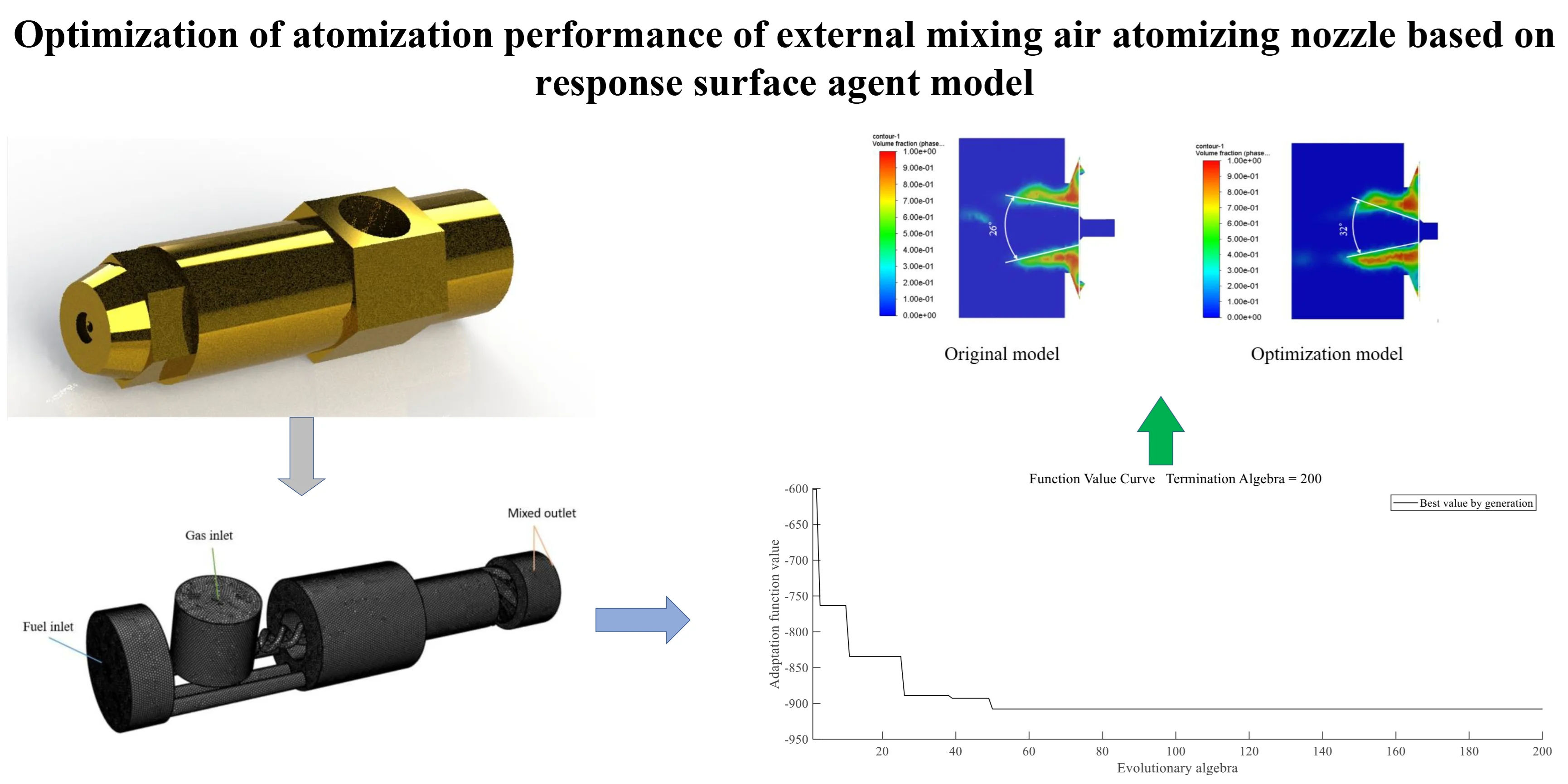
Based on the finding that the atomization performance of the nozzle is affected by its structural parameters, a combination of finite element analysis and structural optimization calculations is used. Finite element analysis was performed through the VOF (Volume of Fluid) module of Fluent software to determine the structural parameters affecting the performance of the atomizing nozzle. The liquid cyclone tank inclination, the length of the flat section at the gas outlet, and the mixing chamber outlet diameter were used as optimization factors. The atomization cone angle and fuel atomization circumferential distribution uniformity index were used as the evaluation indexes of atomization performance. An orthogonal experimental design was carried out based on the above. Proxy model for atomization cone angle and fuel atomization circumferential distribution uniformity index based on response surface method. The optimal structure of the nozzle was obtained by optimization calculation of the agent model by genetic algorithm. The results show that the atomization performance is optimal when the inclination angle of the liquid rotating tank is 42.9, the length of the flat section at the gas outlet is 3.3, and the diameter of the mixing chamber outlet is 5.0. The atomization cone angle increased by 23.07 % compared with the original model, and the fuel atomization circumferential distribution uniformity index decreased by 45.06 %. A new solution for the design of externally mixed air atomizing nozzles is provided.
Highlights
- Multi-objective study of air atomizing nozzles
- Multi-structure parameter optimization study
- Application of response surface agent modeling combined with genetic algorithms
- Orthogonal experimental design and applications
- Research methodology for combining CFD simulation and algorithms
1. Introduction
Externally mixed air atomizing nozzles were characterized by low manufacturing cost, easy replacement, practicality, and simple structure [1]. The atomization process of the nozzle is to form a conical oil film and gas reflux area at the nozzle outlet and then the oil film and the gas flow at a certain angle to impact each other to form uniform micro-droplets [2]. In the combustion chamber of an internal combustion engine, fuel is passed through a nozzle to form an atomized oil, which is thoroughly mixed with the air inside the combustion chamber and burned by the spark plug [3]. As the core component of the gas-liquid two-phase flow atomizer, the structure of the nozzle directly affects the effect and quality of atomization [4], so the study of the internal structure of the atomization nozzle has received more and more attention.
In recent years, scholars at home and abroad mainly used numerical simulation and experimental methods to study the nozzle atomization characteristics and optimize the atomization performance of the external mixed air atomizing nozzle. Wang Guo-Hui et al. [5-7] carried out a two-phase flow simulation analysis and experimental comparison of nozzles based on the VOF method, focusing on the influence of each geometric structural parameter of the nozzle on the atomization performance. It was concluded that the cone angle of the cyclone chamber, the diameter ratio of the exit section of the cyclone chamber, the expansion angle, and the cyclone slot are the structural parameters that affect the atomization quality. AYDINO et al. [8] investigated the effect of nozzle geometry parameters and different gas inlet pressures on the gas velocity at the outlet of a pneumatic atomizing nozzle using numerical simulations. It was concluded that by improving the nozzle geometry, the maximum gas-phase exit velocity can be obtained at the same gas mass flow rate ratio thereby improving the atomization quality. Morda et al. [9] used experimental means to study the atomizing nozzle and concluded that the tilt angle of the rotary groove and the aspect ratio of the rotary groove under different pressure conditions have a significant effect on the atomization performance. Liu Zhao-Miao et al. [10] conducted an experimental study on nozzles using special experimental equipment to investigate the effects of the number of cyclone grooves and nozzle inlet pressure on the liquid film fragmentation and nozzle atomization performance. Ferreira et al. [11] investigated two-phase flow nozzles with internal mixing chambers for the combustion of heavy oil by experimental means and discussed the main parameters and detailed values affecting the optimal design of such nozzles. Ding Biao et al. [12] investigated the atomization process of an external mixed air atomizing nozzle based on experimental and numerical simulation methods and analyzed the effects of water flow rate, water temperature, and air pressure on the atomization characteristics of the nozzle. Wang Bao-Gang et al. [13] used numerical simulation to simulate the atomization velocity and pressure flow field of a mixed air atomizing nozzle and investigated the influence of the local structure of the nozzle on the atomization effect of the nozzle. It was concluded that shortening the length of the nozzle gas-phase channel and changing the shape of the nozzle inlet can enhance the flow velocity near the nozzle gas-phase outlet and improve the nozzle atomization quality. Qiao Wen-Tong [14] combined CFD simulation, experiment, and response surface optimization to study the gas channel of the nozzle and analyzed the influence of the key structure of the nozzle and the working condition parameters on the nozzle atomization performance. It was concluded that the main atomizing gas orifice outer diameter, flare opening tension angle, main atomizing gas orifice pressure, and shaping gas orifice pressure are the key factors affecting the atomization of the nozzle. Zhao Weizhi et al. [15] conducted experiments on nozzles using an independently constructed test experimental system to investigate the effects of air supply pressure and nozzle outlet distance on the atomized particle size of nozzles. Li Wen-Tao [16] simulated and analyzed the nozzle based on numerical simulation and experimental measurement methods and investigated the effects of working conditions and nozzle structure on the atomization performance of coaxial external mixing air atomizing nozzle. It was concluded that the distance between the convergence point of fan-shaped air holes and liquid holes, and the presence or absence of fan-shaped holes are important factors affecting the nozzle atomization cone angle and droplet particle size.
The above scholars through the structural parameters of the external mixed atomization nozzle performance optimization research had achieved results, but on the multi-structural parameters of the integrated impact of the nozzle atomization effect and multi-objective optimization of the research is less. In this paper, the numerical simulation method is applied. The effects of three factors, namely, the inclination angle of the liquid rotating tank, the length of the flat section at the gas outlet, and the nozzle outlet diameter, and their interactions on the atomization performance of the nozzle are explored. Based on the response surface method to establish the agent model of atomization cone angle and fuel atomization circumferential distribution uniformity index, and using genetic algorithm, the optimal nozzle structure parameters are obtained to improve the nozzle atomization performance. This paper aims to optimize the nozzle structure to improve the nozzle atomization performance, which in turn improves the fuel combustion rate and reduces pollution.
2. Nozzle simulation modeling
2.1. Nozzle modeling
Atomizing nozzles are widely used in engines, and the atomization quality directly affects the fuel combustion rate, which in turn affects the power and economy of the engine [17]. The externally mixed air atomizing nozzle studied in this paper is a multi-channel nozzle including a gas channel and a fuel channel, and the structure of the nozzle is shown in Fig. 1. The whole nozzle structure mainly consists of a nozzle, cyclone, and nozzle shell. Among the above parts that make up the nozzle, the structure of the liquid cyclone and the nozzle is relatively complex and is the key part that affects the atomization effect of the nozzle. The liquid cyclone is shown in Fig. 1(b), and three pairs of centre-symmetric cyclone grooves are opened at the top of the right end of the liquid cyclone. The three-dimensional angle between the slotting direction and the axis of the cyclone is the inclination angle of the liquid cyclone slots . Inside the cyclone is a gas channel. The length of the flat section with diameter is called the length of the flat section at the gas outlet. The nozzle is shown in Fig. 1(c), and the mixing chamber outlet diameter is the outlet size at the right end of the nozzle.
Fig. 1Geometric modeling of externally mixed air atomizing nozzle: a) sectional view of nozzle shell; b) cyclone structure; c) sectional view of nozzle

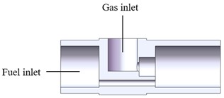
a)
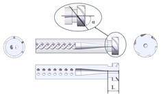
b)
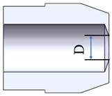
c)
2.2. Controlled equations
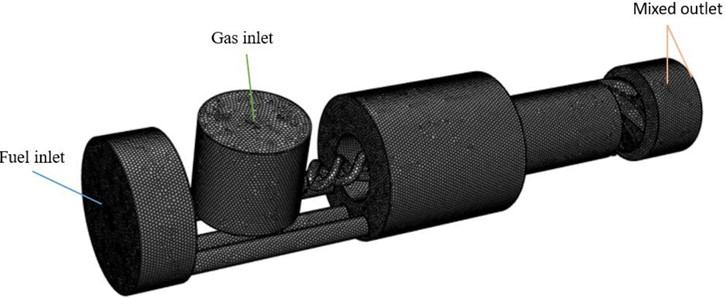
According to the actual nozzle structure parameters, the fluid domain model is established. The overall structure of the external mixed air atomizing nozzle is selected as the physical model for numerical simulation. In addition, to explore the external atomization characteristics of the nozzle. A cylindrical fluid computational domain with a diameter of 12 and a length of 10 is created at the nozzle outlet of the nozzle as shown in Fig. 2.
Fluid simulation software is used in this paper. The flow process in the internal and external fields of the external mixed air atomizing nozzle is simulated based on the VOF method in numerical calculations. HIRT et al. [18] were the first to propose the VOF method, verified through simulation and experiment to be suitable for simulation calculations of incompressible, unmixed fluids. Based on the VOF method simulation, the volume fraction is defined to characterize the percentage of different fluids within the computational grid. The less-dense gas phase is usually defined as the first phase and the liquid phase as the second phase. Where is equal to 0, it means that the computational domain grid is all gas. Its value equal to 1 means that the computational domain grid is all liquid. A value equal to between 0 and 1 means that the fluid distribution inside the grid is a gas-liquid mixture. The VOF model control equations are as follows:
Continuity equations:
where is the fluid density, is the time-averaged velocity.
Momentum equation:
where is the coefficient of dynamic viscosity, and is the fluid pressure.
Realizable - is used as the turbulence model and the and equations are:
where is the turbulent kinetic energy, is the turbulent dissipation rate, is the generation term of turbulent kinetic energy due to the mean velocity, , are the turbulent Prandtl numbers for , and , respectively, is the turbulent viscosity, , and is a constant:
where is the average strain rate, is the kinematic viscosity, and , are constants.
2.3. Mesh partitioning and its mesh-independent validation
In this paper, the ICEM module is utilized to mesh the nozzle fluid domain. Due to the complexity of the internal structure of the nozzle, a non-structural object mesh is used, and the model meshing and computational domain are shown in Fig. 2. In order to ensure that the calculation results are independent of the number of meshes, numerical simulations are performed for different numbers of meshes of the nozzle, as shown in Table 1. It can be seen that 1.5 million mesh can better simulate the atomization characteristics of the nozzle. In comparison, the error of atomization cone angle is not more than 3.55 %. Increasing the number of meshes can reduce the computational speed, so a 1.5 million mesh model is used for simulation and analysis.
Table 1The effect of the number of grids on the calculation results
Number of meshes | Atomizing cone angle (°) |
1000000 | 24.4 |
1500000 | 25.3 |
2200000 | 26.1 |
Fig. 2Calculation area and boundary mesh
2.4. Finite element modeling
The atomization characteristics of an externally mixed air atomizing nozzle are investigated based on the VOF two-phase implicit algorithm. The first phase is set to be air and the second phase is fuel. At the initial moment of numerical simulation, the volume fraction of air at the fuel inlet is equal to 0, and the volume fraction of air at the air inlet takes the value 1. The two-phase interaction model is chosen as the surface tension model. Set the surface tension between air and fuel to 0.04 N/m. The PRESTO algorithm is chosen for the discrete format of the pressure phase. The inlet boundary condition is set to pressure inlet. The fuel pressure was 0.1 MPa, the air pressure was 50 kPa, and the wall boundary conditions were adiabatic with no slip. The external flow field is set up as a pressure outlet. Its pressure is standard atmospheric pressure. According to Chen Xi et al. [19], the turbulence model is selected as the Realizable - turbulence model and the algorithm is calculated using the SIMPLE algorithm for the solution. The initial time step of the calculation is 1e-8, and the maximum time step is 1e-5. The initial time step of the calculation is 1e-8, and the maximum time step is 1e-5. The inlet and outlet flow of the nozzle are monitored, and the difference between the inlet and outlet flows is less than 3 %, so it can be determined that the calculation results have converged.
3. Multi-objective optimization
3.1. Determination of key structural parameters
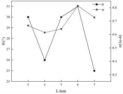
The significance of the effect of nozzle structural parameters on its atomization effect was investigated by one-way experimental method. According to the results of the study, it can be seen that the inclination angle of the liquid cyclone tank , the length of the flat section of the gas outlet and the diameter of the outlet of the mixing chamber have a significant effect on the atomization performance of the nozzle, as shown in Figs. 3, 4 and 5.
Fig. 3Analysis curve of the influence of the inclination angle of the liquid cyclone tank on atomization effect
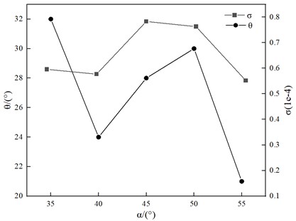
Fig. 4Analysis curve of the influence the length of the flat section of the gas outlet on atomization effect
3.2. Orthogonal experimental design
For the externally mixed air atomizing nozzle, three main structural parameters affect the nozzle atomization characteristics and fuel combustion efficiency. These include the inclination angle of the liquid rotating tank, the length of the flat section at the gas outlet, and the diameter of the mixing chamber outlet. A “three-factor, four-level” orthogonal test design was adopted. Orthogonal tests were designed in terms of the inclination angle of the liquid rotating tank, the length of the flat section at the gas outlet, and the diameter of the mixing chamber outlet. The orthogonal test table was designed by determining the range of levels corresponding to the three structural parameters according to the actual working conditions of the nozzle. The factors and levels are shown in Table 2.
Fig. 5Analysis curve of the influence the diameter of the outlet of the mixing chamber on atomization effect
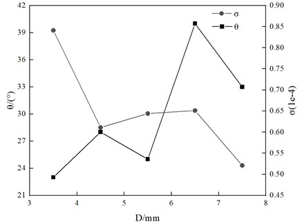
Table 2Orthogonal experiment factor levels table
Parameters | (°) | / mm | / mm |
Level 1 | 40 | 3 | 3.5 |
Level 2 | 45 | 4 | 4 |
Level 3 | 50 | 5 | 4.5 |
Level 4 | 55 | 6 | 5 |
3.3. Response surface agent modeling
Cao Haifeng et al. [20] carried out an optimization study of air-conditioner acoustic enclosures based on the response surface method to improve the acoustic quality of multi-layer acoustic enclosures. Zheng Lei et al. [21] analysed the stability of super high-rise buildings based on response surface method to improve the seismic performance of super high-rise buildings. Response surface agent modeling is a type of proxy model that uses regression equations to fit a functional relationship between input and output parameters, constructing regression equations to represent complex model relationships [22]. The relation effectively replaces the theoretical mathematical model and provides a line of thought for solving the optimal value problem. The second-order response surface agent model has high accuracy and requires a minimum number of ample points of with the expression [23]:
where is th design variable, corresponds to the evaluation index, and , , , and are the different coefficients of the polynomials of the agent model, respectively.
3.4. Application testing of response surface agent model
To determine whether the fitted agent model can accurately represent the response relationship of the external mixing air atomizing nozzle, an accuracy test is required. is used as an evaluation indicator. The expression for is given below:
where is the total deviation sum of squares, is the regression sum of squares, and is the residual sum of squares.
The closer is to 1, the more accurate the model is. When is greater than 0.9, the model is considered to have the required accuracy.
Since the agent model used in this paper involves three factors and therefore three variables, the test function equation is set as a ternary function according to mathematical theory. The purpose of establishing this equation is to test the reasonableness of the orthogonal experimental design and the accuracy of the response surface agent model, and to lay the foundation for subsequent research. A three-dimensional nonlinear test function is given as follows:
Three-factor three-level, three-factor four-level and three-factor five-level orthogonal experimental designs were used to obtain different orthogonal experimental tables. Response surface agent models were built separately based on the experimental data, and the predicted values of the test agent model obtained under different levels of orthogonal experiments were compared with the original values of the test function. The common point of the established table of orthogonal experiments is chosen as the point of comparison. The points of comparison are , , and . Table 3 is a table comparing the accuracy of original and predicted values for different levels of orthogonal experimental designs.
Table 3Errors in the design of orthogonal experiments with different water
Initial value | Projected value | The absolute value of error | ||||
Three-factor 3-level | 5 | 6 | 4 | –41.97 | –44.02 | 2.05 |
Three-factor 4-level | 5 | 6 | 4 | –41.97 | –42.03 | 0.06 |
Three-factor 5-level | 5 | 6 | 4 | –41.97 | –39.62 | 2.35 |
As shown in Table 3, the agent model obtained by sampling with 3 factors and 4 levels is close to the original function in terms of accuracy and can meet the requirements of engineering applications. Therefore, the response surface agent model used in this paper can be designed as a 3-factor, 4-level orthogonal experiment.
3.5. Genetic algorithms
The genetic algorithm mainly includes the following control parameters: crossover probability , population size , and mutation probability [24, 25]. Different control parameters lead to different accuracy of genetic algorithms.
Write the code in MATLAB according to the principle of genetic algorithm. Set the initial population number, crossover rate, and mutation rate, and establish the fitness function based on the agent model. According to the algorithm output fitness function value is to determine whether the genetic algorithm results meet the requirements, meet the output results, or do not meet the loop iteration.
4. Results and discussion
Orthogonal experimental design was carried out by taking 3 factors with 4 levels for each factor. The table of orthogonal experiments is shown in Table 5, with 16 groups of nozzles with different structural parameters. Then, numerical simulations were carried out sequentially to record the results of atomization cone angle θ and fuel atomization circumferential distribution uniformity index [26] for each group. Take the No. 12 nozzle as an example, the parameters are shown in Table 4 to analyse the flow characteristics of the externally mixed air atomizing nozzle. From Fig. 6, it can be seen that after the gas-oil mixture is ejected from the outlet of the nozzle mixing chamber, the velocity is the smallest at the edge, and the closer to the centre, the larger the velocity is. From Fig. 7 it can be seen that the pressure is maximum near the edges and decreases the closer it is to the centre. As can be seen from Fig. 8 and Fig. 9, negative pressure is generated at the nozzle outlet. As the pressure decreases at the outlet, the velocity of the water flow increases, resulting in a higher outside pressure than the pressure at the nozzle outlet. The outside air is then sucked into the nozzle opening, creating a reflux zone at the nozzle opening. Eventually, the fuel is ejected in a hollow conical film.
Fig. 6Mixing chamber exit velocity cloud
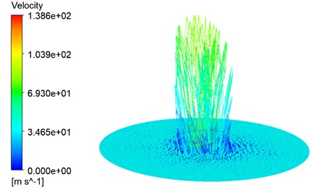
Fig. 7Pressure cloud of the cross-section at Z= 0
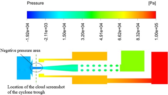
Fig. 8Pressure cloud of cyclone cross-section
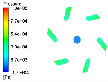
Fig. 9Circumferential distribution of fuel at the outlet of the mixing chamber
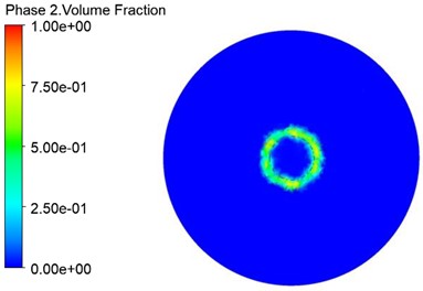
Table 4Parameters of nozzle model No. 12
Liquid cyclone angle (°) | Length of flat section at gas outlet / mm | Mixing chamber outlet diameter / mm |
50 | 6 | 4 |
Table 5Table of orthogonal experiments and results
Numbers | (°) | / mm | / mm | (°) | (1e-4) |
1 | 40 | 3 | 3.5 | 27 | 0.617 |
2 | 40 | 4 | 4 | 31 | 0.522 |
3 | 40 | 5 | 4.5 | 34 | 0.610 |
4 | 40 | 6 | 5 | 35 | 0.634 |
5 | 45 | 3 | 4 | 23 | 0.510 |
6 | 45 | 4 | 3.5 | 16 | 0.722 |
7 | 45 | 5 | 5 | 40 | 0.461 |
8 | 45 | 6 | 4.5 | 27 | 0.693 |
9 | 50 | 3 | 4.5 | 25 | 0.730 |
10 | 50 | 4 | 5 | 41 | 0.652 |
11 | 50 | 5 | 3.5 | 18 | 0.920 |
12 | 50 | 6 | 4 | 26 | 0.830 |
13 | 55 | 3 | 5 | 45 | 0.810 |
14 | 55 | 4 | 4.5 | 15 | 0.563 |
15 | 55 | 5 | 4 | 25 | 0.578 |
16 | 55 | 6 | 3.5 | 31 | 1.100 |
4.1. Analysis of variance
Factors were analysed for Analysis of variance using the function as shown in Tables 6 and 7:
where is the degree of freedom corresponding to each factor or interaction between factors, and is the sum of error degrees of freedom.
Checking the table, , when , it indicates that the factor has a significant effect on the indicator. denotes the experimental mean at the th level of a factor [27].
As shown in Table 6, the variance values and are significant for the effects of liquid cyclone tank inclination and mixing chamber outlet diameter on the atomization cone angle. From , , , the following law can be obtained. The atomization cone angle decreases and then increases with the inclination angle of the liquid rotating tank and the length of the flat section at the gas outlet. The atomization cone angle shows a tendency to increase and then decrease and then increase with the outlet diameter of the mixing chamber.
Table 6Analysis of variance for atomization cone angle
Parameters | (°) | / mm | / mm |
9.29 | 1.35 | 27.01 | |
31.75 | 30 | 23 | |
26.5 | 25.75 | 27.5 | |
28.75 | 29.25 | 25.25 | |
29 | 31 | 40.25 |
As shown in Table 7, the effect of the length of the flat section at the gas outlet and the diameter of the mixing chamber outlet on the homogeneity of the circumferential distribution of the fuel atomization is significant, as derived from the values of the variance and . From , , , can be obtained the law. The uniformity of circumferential distribution of atomization shows a tendency to decrease, then increase, and then decrease with the inclination angle of the liquid rotating tank and the outlet diameter of the mixing chamber. The uniformity of atomization circumferential distribution tends to decrease and then increase with the length of the flat section at the gas outlet.
Table 7Analysis of variance of fuel atomization circumferential distribution uniformity
Parameters | (°) | / mm | / mm |
0.34 | 4.00 | 16.36 | |
0.596 | 0.667 | 0.840 | |
0.597 | 0.615 | 0.610 | |
0.783 | 0.642 | 0.649 | |
0.763 | 0.814 | 0.639 |
4.2. Regression analysis
To reflect the law and trend of the influence of nozzle structure parameters on the atomization cone angle and fuel atomization circumferential uniformity. So, the relationship between the indicators in Table 6 and Table 7 and the factors were fitted to get the law curve. In this case, the relationship between the atomization cone angle and the mixing chamber outlet diameter was fitted using a cubic fit. The relationship between fuel atomization circumferential uniformity and the length of the flat section at the gas outlet and the diameter of the mixing chamber outlet, respectively, were fitted three times. The relationships of other structural parameters with the atomization cone angle and fuel atomization uniformity index were fitted by conformal fitting.
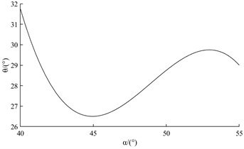
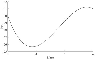
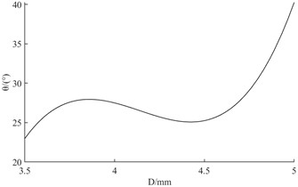
Fig. 10Fitted curve of atomization cone angle
a) Fitted relationship between liquid swirl tank angle and circumferential uniformity of fuel atomization
b) Fitted relationship between the length of the flat section at the gas outlet and the circumferential uniformity of fuel atomization
c) Fitted relationship between mixing chamber outlet diameter and circumferential uniformity of fuel atomization
It can be obtained from the three curves in Fig. 10. The mixing chamber outlet diameter has the most significant effect on the atomization cone angle. The second is the liquid swirl tank inclination. The least influence is the length of the flat section at the gas outlet. Among them, the atomization cone angle shows a tendency to decrease and then increase as the inclination angle of the liquid cyclone trough increases. When is taken in the range of 40 to 45, the atomization cone angle has a significant tendency to decrease. As the length of the flat section at the gas outlet increases, the atomization cone angle shows a tendency to decrease and then increase. When the value of is taken in the range of 3 to 4, there is a significant tendency for the atomization cone angle to decrease. The significance of the increase in the atomization cone angle was decreasing when was taken in the range of 4 to 6. As the diameter of the mixing chamber outlet increases, the atomization cone angle shows a tendency to increase, then decrease, and then increase. When is taken in the range of 4.5 to 5, there is a significant tendency to increase the atomization cone angle.
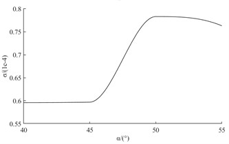
The three curves in Fig. 11 can be shown. The mixing chamber outlet diameter has the most significant effect on the circumferential uniformity of fuel atomization. The second is the length of the flat section at the gas outlet. The least significant effect is the inclination angle of the liquid rotating tank. Among them, the fuel atomization circumferential uniformity index shows a tendency to remain constant and then increase and then decrease as the inclination angle of the liquid cyclone tank increases. When the value of is taken in the range of 45 to 50, the index of circumferential uniformity of fuel atomization has a tendency to increase significantly. As the length of the flat section at the gas outlet increases, the fuel atomization circumferential uniformity index shows a tendency to decrease and then increase. When the value of is taken in the range of 5 to 6, the index of fuel atomization circumferential uniformity has a tendency to increase significantly. As the diameter of the mixing chamber outlet increases, the fuel atomization circumferential uniformity index shows a tendency to decrease, then increase, and then decrease. When the value of is taken in the range of 3.5 to 4, the fuel atomization circumferential uniformity index has a tendency to decrease significantly.
Fig. 11Fitted curve of fuel atomization circumferential distribution uniformity
a) Fitted relationship between liquid swirl tank angle and circumferential uniformity of fuel atomization
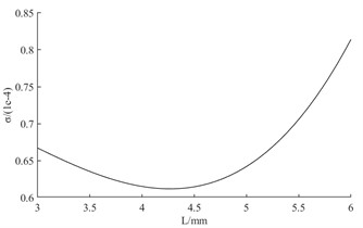
b) Fitted relationship between the length of the flat section at the gas outlet and the circumferential uniformity of fuel atomization
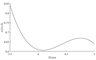
c) Fitted relationship between mixing chamber outlet diameter and circumferential uniformity of fuel atomization
4.3. Modeling response surface agent
Based on the principles of response surface agent modeling and orthogonal experimental tables, a response surface function is fitted with the expression:
The regression coefficient for the equation of atomization cone angle and for the equation of flow coefficient were calculated. This indicates that the equations are fitted with high accuracy. Thus, it can be fitted with this response surface model to simplify the computational process. In this paper, the maximum atomization cone angle and the minimum fuel atomization circumferential uniformity index are taken as the optimum atomization effect. The mathematical model is:
where is the atomization cone angle, and is the fuel atomization circumferential distribution uniformity index. where , , are the liquid cyclone tank inclination, the length of the flat section at the gas outlet, and the mixing chamber outlet diameter, respectively.
In this paper, the ideal point method of multi-objective planning is used. Since the atomization cone angle has a greater influence on the atomization performance than the fuel atomization circumferential uniformity index , the weights of 0.7 and 0.3 are used as the comprehensive indexes, respectively. The atomization cone angle and the oil atomization circumferential uniformity index are normalized with the objective function:
4.4. Optimization calculation and result analysis
After obtaining the response relationship equation, the mathematical model was written in MATLAB. According to the control parameters required by the genetic algorithm, the number of iterations is set to 1000, the population size is 200, the crossover probability is 0.6 and the variance probability is 0.05. Then, the optimization is carried out by the optimization process of the genetic algorithm. The iteration curve is shown in Fig. 12, and the optimized nozzle parameters are shown in Table 8.
Fig. 12Genetic algorithm to optimize iteration curve
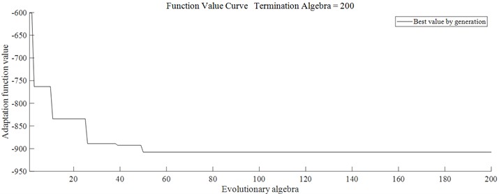
Table 8Optimized nozzle structure parameter
Design variables | Liquid cyclone angle (°) | Length of flat section at gas outlet / mm | Mixing chamber outlet diameter / mm |
42.9 | 3.3 | 5.0 |
The parameters obtained after optimization with the genetic algorithm are used to build the nozzle simulation model and simulation analysis, and the simulation results obtained are shown in Table 9.
Table 9Simulation results after optimization
Evaluation indicators | value |
32 | |
0.456 |
As shown in Fig. 13, the atomization cone angle increases by 23.07 % relative to the original model, and the fuel atomization circumferential uniformity index decreases by 45.06 % relative to the original model. The optimized nozzle injects fuel more evenly and improves its atomization quality. It achieves the purpose of improving the fuel combustion rate and reducing the pollution of exhaust gas emissions to the environment.
Fig. 13Comparison chart of atomization effect before and after optimization
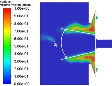
a) Original model
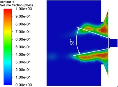
b) Optimization model
5. Conclusions
Based on the VOF method, the flow characteristics inside the externally mixed air atomizing nozzle were simulated. The effects of nozzle structural parameters on the atomization performance were investigated by orthogonal experimental design. The conclusions are as follows:
1) Among the three structural parameters the nozzle mixing chamber outlet diameter has the most significant effect on the atomization characteristics. The increase in mixing chamber outlet diameter significantly improves the circumferential uniformity of fuel atomization and increases the atomization cone angle. The increase in the inclination of the liquid swirl tank and the length of the flat section at the gas outlet reduces the atomization cone angle and decreases the circumferential distribution uniformity of the fuel atomization to some extent.
2) The simulation results before and after nozzle optimization are compared. The results show that when the inclination angle of the liquid swirl tank is 42.9, the length of the flat section at the gas outlet is 3.3, and the diameter of the outlet of the mixing chamber is 5.0, the atomization cone angle increases by 23.07 % compared with the pre-optimization period, and the index of the circumferential homogeneity of fuel atomization decreases by 45.06 %. The atomization quality of the nozzle was improved, providing a reference for the rational design of nozzle structure parameters.
References
-
B. Zheng, L. Ji, L. Xia, and Z. Kong, “Atomization performance of a novel externally mixed pneumatic nozzle,” (in Chinese), Missile and Space Launch Technology, No. 1, pp. 56–60, 2009.
-
H. Ling-Yun and H. Xiao-Chun, Handbook of Nozzle Technology. Beijing: Sinopec Press, 2007.
-
S.-M. Chen, “Study on the effect of head structure parameters on flow field and atomization characteristics of combustion chamber for naval combustion engine,” University of Chinese Academy of Sciences, 2021.
-
Y. Zhang, T. He, X. Yu, L. Liang, and Y. Zhang, “Simulation and test of atomization process of two-fluid atomizer,” (in Chinese), Agricultural Engineering, Vol. 13, No. 8, pp. 107–112, 2023.
-
C. Wang, G. He, and C. Hu, “Experimental and numerical study of a cyclonic nozzle,” (in Chinese), Propulsion Technology, No. 1, pp. 28–32, 2003.
-
J. Liu, Q. Li, Z. Wang, and H. Wu, “Simulation of flow processes inside centrifugal nozzles based on the VOF method,” (in Chinese), Journal of Aerodynamics, Vol. 26, No. 9, pp. 1986–1994, 2011.
-
G. K. Liu, G. Liu, G. Pan, and H. T. Zheng, “Numerical study on the effect of structural parameters on nozzle performance,” (in Chinese), Aero Engines, Vol. 41, No. 5, pp. 28–32, 2015.
-
O. Aydin and R. Unal, “Experimental and numerical modeling of the gas atomization nozzle for gas flow behavior,” Computers and Fluids, Vol. 42, No. 1, pp. 37–43, Mar. 2011, https://doi.org/10.1016/j.compfluid.2010.10.013
-
Morda Dou Yitao, Zhen Zhao, Xuetao Li, and Meiye Li, “Experimental study on the atomization performance of three-cyclone combustion chamber nozzles,” (in Chinese), Aero Engines, Vol. 46, No. 4, pp. 82–86, 2020.
-
Z. Liu, Z. Li, J. Lin, and Y. Pang, “A study on the effect of pressure conditions on liquid film breakup and atomization of centrifugal nozzles with different numbers of spinning slots,” (in Chinese), Journal of Mechanical Engineering, Vol. 57, No. 4, pp. 247–256, 2021.
-
G. Ferreira, J. A. García, F. Barreras, A. Lozano, and E. Lincheta, “Design optimization of twin-fluid atomizers with an internal mixing chamber for heavy fuel oils,” Fuel Processing Technology, Vol. 90, No. 2, pp. 270–278, Feb. 2009, https://doi.org/10.1016/j.fuproc.2008.09.013
-
B. Ding, R. Yuan, O. Li, and Y. Ma, “Characterization of atomized particle size based on externally mixed air atomizing nozzles,” (in Chinese), Agricultural Equipment and Vehicle Engineering, Vol. 59, No. 8, pp. 87–90, 2021.
-
B.-G. Wang, C.-Q. Li, J.-F. Zhang, S. Wang, S.-J. Li, and R.-R. Gan, “Improvement and simulation study of Fluent-based externally mixed pneumatic atomizing nozzle,” (in Chinese), Electromechanical engineering, Vol. 40, No. 2, pp. 159–168, 2023.
-
W. Qiao, “Study of air flow path of external mixed air atomizing nozzle and optimization of spraying performance,” China Jiliang University, 2022.
-
W.-Z. Zhao, S.-C. Ge, X.-W. Zhang, L. Sun, X. Chen, and J.-X. Chen, “Study on the atomization characteristics of supersonic siphon air-atomizing nozzles,” (in Chinese), Mining Safety and Environmental Protection, Vol. 50, No. 4, pp. 19–24, 2023.
-
W. T. Li, “Study on atomization performance of coaxial externally mixed air atomizing nozzle,” China Jiliang University, 2020.
-
J. Zhao, “Study of gas-liquid two-phase flow and jet spray with flow focusing/fuzzy nozzle,” Beijing Jiaotong University, 2022.
-
C. W. Hirt and B. D. Nichols, “Volume of fluid (VOF) method for the dynamics of free boundaries,” Journal of Computational Physics, Vol. 39, No. 1, pp. 201–225, Jan. 1981, https://doi.org/10.1016/0021-9991(81)90145-5
-
X. Chen, S.-C. Ge, Z.-W. Zhang, and D.-J. Jing, “Numerical simulation analysis based on Fluent multi-nozzle spray interference,” (in Chinese), Journal of Environmental Engineering, Vol. 8, No. 6, pp. 2503–2508, 2014.
-
H.-F. Cao et al., “An investigation of the acoustic enclosure of an air conditioning compressor using response surface analysis and topological rigidity optimization,” Shock and Vibration, Vol. 2024, p. 1909530, May 2024, https://doi.org/10.1155/2024/1909530
-
L. Zheng, Z. Liu, H. Dang, X. Guo, and Y. Wu, “Seismic performance of super high-rise building structure with dual lines of defense based on response surface optimization algorithm,” Shock and Vibration, Vol. 2022, p. 2464675, Sep. 2022, https://doi.org/10.1155/2022/2464675
-
B. Cui, W. Kong, and K. Ma, “Application of polynomial response surface agent model in the optimization of column structure,” (in Chinese), Mechanical Design, Vol. 34, No. 4, pp. 44–48, 2017.
-
P. P. Ji, Y. H. Li, and B. Z. Chen, “Structural strength analysis of bogie frame configuration considering parameter uncertainty,” (in Chinese), Chinese Mechanical Engineering, Vol. 30, No. 1, pp. 22–29, 2019.
-
F. Li and T. Y. Zhao, “An exploration of the theory of genetic algorithm and its application progress,” (in Chinese), Technology and Market, Vol. 23, No. 1, p. 87, 2016.
-
F. Shuang, “Theoretical study of genetic algorithm and its application,” (in Chinese), Technology and Innovation, No. 23, pp. 21–22, 2017.
-
Y. Ai, Y. Sun, H. Chen, and A. Liu, “Relational equation for particle distribution criterion of central jet type nozzle,” (in Chinese), Journal of South Central University (Natural Science Edition), Vol. 46, No. 5, pp. 1909–1914, 2015.
-
Z. Sun, Z. Hu, D. He, and X. Wu, “Optimization study on the atomization performance of centrifugal nozzles for water injection desuperheating valve,” (in Chinese), Hydraulics and Pneumatics, Vol. 46, No. 11, pp. 124–131, 2022.
About this article
This work was financially supported by National Natural Science Foundation of China (No. 11872043).
The datasets generated during and/or analyzed during the current study are available from the corresponding author on reasonable request.
Zegang Sun: conceptualization, writing-review and editing, supervision, project administration, funding acquisition. Zhonghao Zheng: methodology, validation, and writing-original draft preparation, writing-review and editing. Jiabin Zhang: methodology, validation, and writing-original draft preparation, writing-review and editing. Fan Zhao: methodology, validation, and writing-original draft preparation, writing-review and editing.
The authors declare that they have no conflict of interest.
