Abstract
The rack and pinion shiflifts feature its capability of fortification against extreme accidents of unbalance of ship chamber. This requires the load transfer systems of nut columns to be able to transfer the huge and centralized loads from the safety mechanisms to the tower columns in a distributive bearing way. Aiming at exploring a design-oriented computation method for the nut column load transfer systems (NCLTSs), a sandwich-type semi-infinite coupling Winkler-Pasternak double elastic foundation beam model (DEFBM) has been established, with a distributive assumption of the axial constrain force on the interfaces between the nut columns, mortar beds, adjusting beams and the second stage concrete based on the physical model test, has been proposed. A set of formulars for describing the distribution of deflections, internal forces and stress of nut columns and adjusting beams have been derived. A case study of the Three-Gorges shiplift has been conducted to demonstrate the approach of calculation of internal forces and stress by applying the formulas based on sandwich-type Winkler-Pasternak DEFBM, showing the convenience and rationality of the method to parametric layout design of the nut columns and adjusting beams in NCLTSs. Not only to NCLTSs and rack load transfer systems of shiplifts, the sandwich-type Winkler-Pasternak DEFBM also supplies the reference to the modeling and analysis of the rail-embedment structural systems broadly applied in hydraulic engineering.
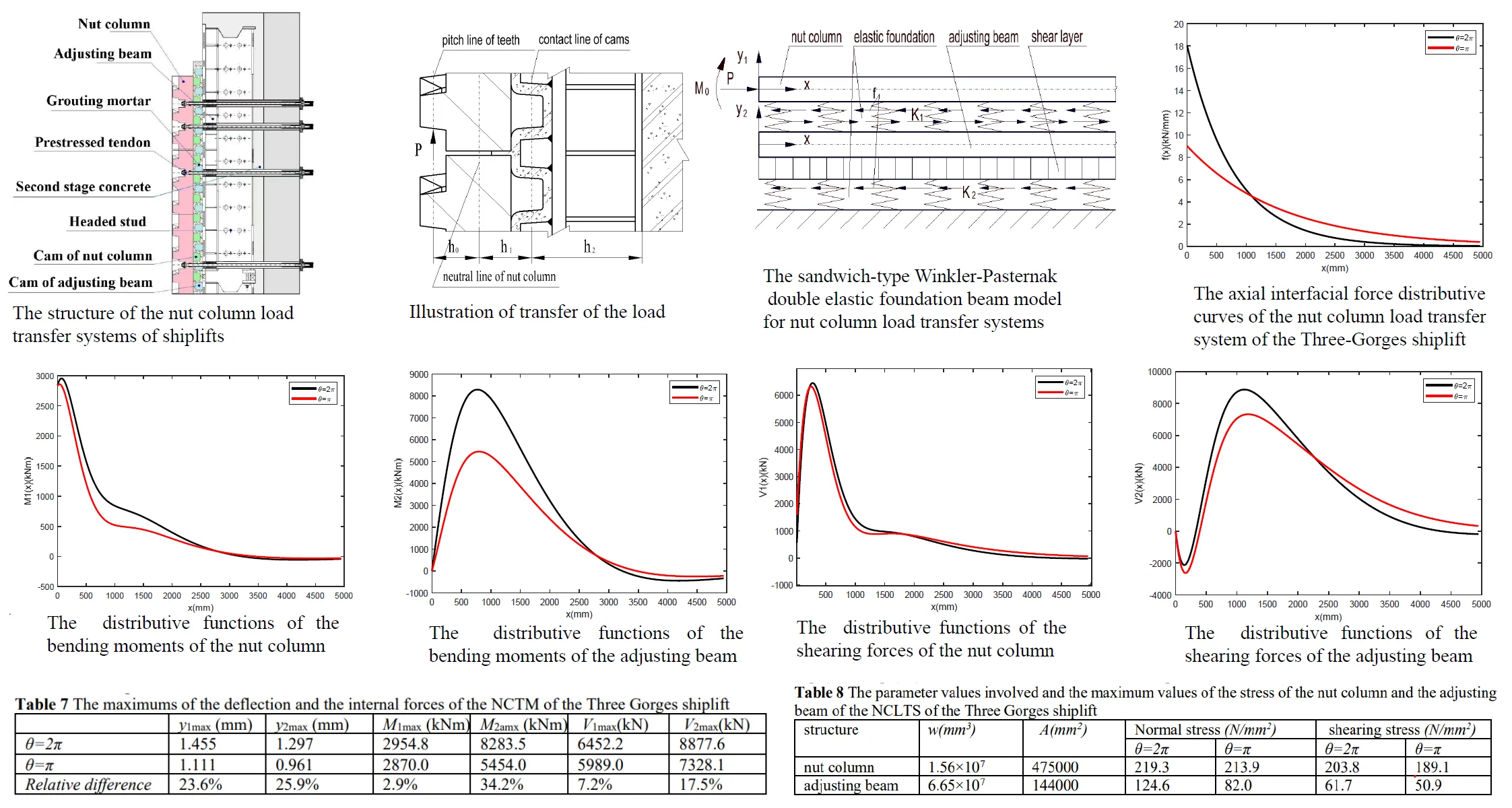
Highlights
- Based on the features of the structure and loading of the nut column load transfer system of rack and pinion shiplifts ,the semi-infinite coupling Winkler-Pasternak double elastic foundation beam model for analysis of the internal forces has been proposed.
- Based on the physical model tests, the exponential distribution presumptive mode of the axial intrenal constraint distributive force which describes the concentration of the axial intrenal constraint force has been proposed.
- A set of formulars for describing the distribution of deflections, internal forces and stress of nut columns and adjusting beams have been derived.
- A case study of the Three-Gorges shiplift has been conducted to demonstrate the approach of calculation of internal forces and stress based on Winkler-Pasternak double elastic foundation beam model.
- The conputational method based on the sandwich-type Winkler-Pasternak double elastic foundation beam model is suitable for primary design stages as the method is on the safe side.
1. Introduction
As one of two forms of navigation facilities, shiplifts have obtained rapid development in China in the past thirty years in the construction of the hydro-junction projects due to their advantage in adaption to large water heads [1]-[3]. The full balance rack and pinion vertical shiplifts have nice performance in safety, so they have been employed and constructed in the Three-Gorges hydro-junction project and the Xiangjiaba hydro-power project, of which the shiplifts are the largest ones in China as far as their design ship tonnages and lifts are concerned [4]-[7].Both the Three-Gorges shiplift and the Xiangjiaba shiplift have operated well since the completions of construction and played important role in functioning the navigation of the projects [8], [9].
The rack and pinion vertical shiplifts feature gravitational balance between the ship chambers and counterweights, and driving by the racks and pinions, and security by the safety mechanisms [10], [11]. The unbalanced loads of the shiplifts caused by deviations of the water depths from the design ones are overcome by the driving mechanisms of the shiplifts in ship chamber lifting process. When the unbalanced load exceeds the set values, the shiplifts stop lifting and the bearing of the ship chamber shifts from the driving mechanisms to the safety mechanisms, and the extra loads beyond the set values are borne by the safety mechanisms and are transferred to the concrete structure through the NCLTSs. The extreme accidents, such as the thorough water leakage accident (TWLA), should be taken into account in design of the NCLTSs of shiplifts [12]. As the probability of occurrences of the extreme accidents of unbalance are rare, and the unbalance load is very slowly applied during the accidental process(water leaking for example), the main concern in design of NCLTSs is the static strength.
The NCLTSs of the rack and pinion shiplifts are complex structure systems with the elements of different materials characteristics and featuring the contact and prestress, of which nut columns and adjusting beams are most important structures. At present there have been no mature method available for designer to calculate the stress of the nut columns and adjusting beams of the NCLTSs in codes for shiplifts and other hydraulic steel structures [12, 13]. For the Three Gorges shiplift, the first rack and pinion shiplift in China and the largest one in the world, the information about the stress of structures of the NCLTSs was mainly obtained by the physical model tests during the design process [14], [15], in which an integral physical model with the scale of 1:2 and a local physical model with the scale of model 1:1 have been built for the research of the stress and deformation of the parts of the NCLTS. For the computation of stress of the structures of the NCLTSs, the primary explorations have been conducted. A FEA model for the NCLTS of the Three-Gorges shiplift has been established by Li, Liu and Zhang et al. [16], which contains almost all structural elements indicated in Fig.1. The mechanical loads in the accidental cases mentioned above together with the thermal load related to the variation of the temperature have been applied on the structural system, and the stress and displacements have been computed. The similar FEA studies on the stress and deformation of the NCLTS of the Three-Gorges shiplift have also been performed by Niu, et al. [11]. Liu has also conducted in his dissertation the research of the main stress of the structures, such as nut columns, adjusting beam, mortar, concrete, and tendons of the NCLTS of the Three Gorges shiplift, and has assessed the safety margin of the NCLTS [17]. Although the FEA modelling is powerful means for designers to obtain the detail information about the distributions of the stress and deformation of all the elements, but the application of the FEA is time -consuming and expensive as the complexity in the structure and the loading characteristics of contact and prestress, so it is not suitable to the layout design and parametric structural design in the primary design stages, but to the thorough verification of the strength and deformation of the all structural elements in the final design stage.
On the other hand, in the community of research realm of the analysis of elastic foundation beams, there are rare literatures on mechanic models which describe the sandwich-like structures of double-layer elastic foundation beams, which have been broadly applied in hydraulic engineering, such as rail-embedment structures in gate systems for example. Almost all the literatures have been focused on the structures of single beam with single-layer foundation [18-23]. An exception is the paper by the author and Wang, who have initiated exploration of analytical study of NCLTSs and rack load transfer systems by building the sandwich-type Winkler-Winkler DEFBMs for the NCLTSs and the rack load transfer systems [24]. There are two flaws in this paper about modelling of the NCLTSs. The first one is that the axial constrain forces on the interface between nut columns and grouting mortar layer and the interface between the adjusting beam and the second concrete have been ignored by assumption that the transfer of the axial force from the nut to the adjusting beam occurs just at the loading end of the nut column. The second one is that the fact that the adjusting beams are partially embedded has been ignored and the shearing constrain of the concrete on the adjusting beams has not been applied. The two flaws make the model does evidently not coincide with practical situation of load transfer of the NCLTSs.
The aim of this paper is to supply the simple and convenient method for computation of the internal forces and the stress of the nut column and adjusting beam, to satisfy the requirements for multi-scheme comparison and parametric layout design of the NCLTSs in primary design stages. For this purpose, I initiate two novelties comparing to the work done before. The first is that the author simplifies the complex NCLTSs according to structural feature to the sandwich-type Winkler-Pasternak double elastic foundation beam model, of which the nut columns are Winkler elastic foundation beams, and the adjusting beams are Pasternak elastic foundation beams. The second is that the author proposes the exponential distributive assumption of the axial interfacial constrain force to quantitatively describe the degree of the centralization of the axial interfacial constrain force, which is convenient to analysis of influence of the centralization on the internal forces and stress, rather than simply applies the centralized axial constrain force which is not in accord with practical situation.
Furthermore, the sandwich-type structures are broadly applied in hydraulic engineering. For example, the guiding rails for gates are borne on the surfaces of the second stage concrete, and the embedded parts, which are for the adjustment of the installation precision, are embedded in the second stage concrete. There are no ways to analysis the stress of the steel embedded parts. The sandwich-type Winkler-Pasternak DEFBM not only results directly in the method to analysis the internal forces and stress of the nut columns and adjusting beams of NCLTSs, but also provide the approach to analysis the internal forces and stress of this sorts of the sandwich like rail-embedment structural systems. It is predictable that the initiation and development of the sandwich-type Winkler-Pasternak DEFBM will enlarge the realm of the elastic foundation beam theory and its application in engineering.
2. Modeling of the NCLTSs
2.1. Structure features and load transfer mechanism of NCLTSs
A NCLTS consists of nut columns, adjusting steel beams, grouting mortar, the second stage concrete, the first stage concrete and the prestressed tendons, as shown in Fig. 1. When an accident of unbalance between the ship chamber and the counterweights occurs, the vertical loads on the flank surfaces of the threads of the nut columns from the safety mechanisms of ship chambers are transferred to the tower columns through the nut columns, grouting mortar, the adjusting beams, the second stage concrete and the first stage concrete, as shown in Fig. 2. The fixed bearings have not been applied in the NCLTSs to avoid huge centralized supporting reactions which the thin-walled structure of the column tower cannot bear, so a distributive load transfer structure has been employed. By applying the enough initial compressive internal force inside the whole load transfer system through the prestressed tendons during installation, the normal forces on the interfaces between the nut columns and grouting mortar, and the interfaces between adjusting beams and the second stage concrete, are always pressures rather than tensions, so the bilateral distributive constraints of nut columns and adjusting beams by grouting mortar and the second stage concrete are established. No matter which directions of external loads are, the normal constraints of nut columns by the grouting mortar and of adjusting beams by the second stage concrete can be treated as bilateral ones rather than unilateral ones. Based on this, the nut columns and adjusting beams may be treated as beams on elastic foundations with bilateral bearings.
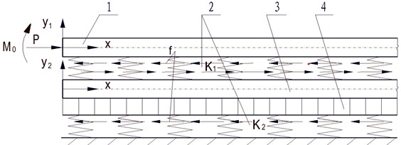
The sandwich-type Winkler-Pasternak DEFBM of NCLTSs is shown in Fig. 3, in which nut columns are supported on the elastic foundation of grouting mortar and the adjusting beams are partially embedded in the second stage concrete. The vertical load is supposed to act on the pitch line of the tooth flank of the nut column at the one end which is most unfavourable loading position as far as the strength and deformation of NCLTSs are concerned. In the DEFBM the vertical load is shifted to the neutral line of the nut column by applying a bending moment at the end. The vertical load , which is the design load for the nut columns corresponding to the specified accidental case to be fortified in the design of shiplifts, is shown in Fig. 3 in horizontal direction to save page space, is transferred further from the nut column to the adjusting beam through the cams of the nut columns and adjusting beam and the grouting mortar which fill the gap between the cams, and to the second stage concrete by the adhesion and friction between the surfaces of the adjusting beam and the second concrete.
Considering that the axial force and bending moment are applied at the left end of the nut column as shown in Fig. 3, the lengths of nut columns and the adjusting beams are large enough comparing to the dimensions of the cross sections, we model the nut columns as a semi-infinite Winkler elastic foundations beam and the adjusting beams as a semi-infinite Pasternak elastic foundations beam that behave like two arrays of independent springs [25], [26]. Accordingly, the axial interfacial distributive constrain force between the nut column and the adjusting beam is supposed to be in the following form based on the results of physical model test on the NCLTS of the Three Gorges shiplift [14], [15]:
where and are positive constants that measure the degree of the concentration of the distribution of the axial interfacial constrain force, is the length of the single segment of the nut column and adjusting beam, is a dimensionless parameter which is suggested to take value between and 2.
Fig. 1Diagram of the NCLTS: 1 first stage concrete, 2. Nut column, 3. Adjusting beam, 4. Grouting mortar, 5. Prestressed tendon, 6. Headed stud, 7. Second stage concrete, 8. Cam of nut column, 9. Cam of adjusting beam
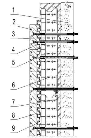
Fig. 2Illustration of transfer of the load
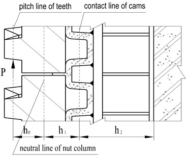
Fig. 3Diagram of the sandwich-type Winkler-Pasternak DEFBM: 1. Nut column, 2. Elastic foundation, 3. Adjusting beam, 4. Shearing layer
2.2. Mathematical description of DEFBM of NCLTSs
In order to obtain the differential equations of the deflections of the nut column and the adjusting beam, I start by analysis of the balance of forces of the micro sections of the nut column and the adjusting beam. The Fig. 4 is the diagram for illustrating the forces on the micro segments of the nut columns and adjusting beams, in which it is supposed that upward deflections are positive and the distributed reactions of the elastic foundations on the beams caused by upward deflections of the beams are positive. The signs of the bending moments and shearing forces are regulated in accord with Material Mechanics. We can see that the nut column is modeled as a Winkler elastic foundation beam from Fig. 4(a), and that the adjusting beam is modeled as a Pasternak elastic foundation beam from Fig. 4(b).
Fig. 4Illustrations of forces and moments in micro-segments in Winkler-Pasternak DEFBM
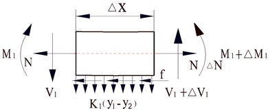
a) Force and moment in a micro-segment of the nut column
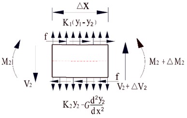
b) Force and moment in a micro- segment of the adjusting beam
According to Fig. 4, we can write the equilibrium equations for forces and bending moments of the micro segments of the nut columns and the adjusting beams as followings.
For the nut column:
For the adjusting beam:
where and denote respectively the deflections of the nut column and the adjusting beam, and respectively the shearing force and the bending moment of the nut column, and respectively the shearing force and the bending moment of the adjusting beam, and respectively the spring constants for the mortar and the second stage concrete, is the distance from the neutral axis of the nut column to the contact line of the cams, and the distance from the contact line of the cams to the reluctant action line of axial force between the adjusting beam and the second stage concrete as shown in Fig. 2.
For an elastic foundation beam with width , the spring constant can be determined as followings [18], [27]:
where is the thickness of the foundations, and and are respectively the elastic modulus and the Poisson’s rations of the foundation materials. is the shearing coefficient of the elastic foundation of the adjusting beam which can be calculated by the formula [28]:
where is the embedded depth of the adjusting beam in the second stage concrete.
In Eq. (2-4), let 0 we get equilibrium differential equation for the nut column:
We can write the formular for the distribution of the axial internal force of the nut column from Eq. (11) and the axial internal bound condition shown in Fig. 3:
Differentiating Eq. (13) w.r.t the argument and combining with Eq. (12) and Eq. (1) yields:
According to the material mechanics, for the nut column with small deflection, there exists following formula:
where is the elastic modulus of steel and is the area inertial moment of the nut column. Substituting Eq. (16) into Eq. (15) yields:
For the adjusting beam, in Eq. (5-6), let 0 we have the following equations:
Differentiating Eq. (19) w.r.t the argument and combining with Eq. (18) and Eq. (1) yields:
There exists following identity for the adjusting beam:
where is the area inertial moment of the adjusting beam. We obtain the following equation by substituting Eq. (21) into Eq. (20):
The Eq. (17) can be changed into the following form:
Substituting Eq. (23) into Eq. (22) yields:
By reorganization of Eq. (24), the following equation is derived:
Eq. (25) can also be written in the following simpler form:
where:
Eq. (26) is called the control differential equation for deflection of the nut column.
2.3. Derivation of formulas for computation of internal forces of the NCLTSs
According to the theory of linear ordinary differential equations with constant coefficients, the solution to the ordinary differential Eq. (27) is the sum of a general solution and a particular solution :
The general solution is obtained by numerically solving the characteristic equation of the differential Eq. (26), which is:
The roots of the characteristic equation are eight complex numbers (1, 2), where is the imaginary unit. The general solution is formally written as:
where (1-8) are the constants to be determined by the boundary conditions. By the assumption that both the nut column and adjusting beam are treated as semi-infinite beams on elastic foundations, the deflection of the nut column is zero when . It is easy to deduce by the semi-infinite beam presumption that , , , are equal to zeros. The general solution to the Eq. (26) should be written in the following form:
The particular solution is written as:
where is a constant to be determined. Substituting Eq. (31) into Eq. (26) yields:
We obtain:
Substituting Eq. (30-32) into Eq. (28) yields:
Substituting Eq. (33) into Eq. (23), we obtain function of the deflection of adjusting beams w.r.t argument :
where:
The internal bending moment and the shearing force of the nut columns are respectively derived according to Eq. (13), Eq. (16), Eq. (19) and Eq. (21):
The internal bending moment of the adjusting beam is derived as following:
Substituting Eq. (35) into Eq. (40) yields:
The internal shearing force of the adjusting beam is derived as following:
Substituting Eq. (35) into Eq. (42) yields:
The boundary conditions for the nut columns and adjusting beams are as followings as shown in Fig. 3:
where is the distance from the pitch line of the teeth of the nut columns to the neutral line of the adjusting beams as shown in Fig. 2.
Substituting the formulars Eqs. (38-39), Eq. (41), Eq. (43) into Eq. (44), we obtain following equations:
where:
From Eq. (45), the coefficients , , , can be computed with the following formula:
Substituting the values of the constants , , , into Eqs. (38-39), Eq. (41) and Eq. (43), we have derived the formulars for the internal bending moments and internal shearing forces of the nut columns and adjusting beams.
Further investigation has been made by calculation of the bending normal stresses and bending shearing forces of the nut columns and adjusting beams, to assess the strength of the nut columns and adjusting beams in NCLTSs of the shiplifts. The formulars for calculation of normal stress and shearing stress and the strength design condition are as followings [12]:
where and denote respectively the normal stress of the nut columns and the adjusting beams, and and the shearing stress of the nut columns and the adjusting beams, and denote respectively the maximum values of the internal bending moments, and and respectively the maximum values of the internal shearing forces. and denote respectively the section modulus of the nut columns and the adjusting beams, the section area of the nut column and the summed areas of the sections of the webs of the adjusting beams, [] and [] denote respectively the allowed the maximum normal stress and the maximum shearing stress of the nut column, and [] and [] respectively the maximum normal stress and the maximum shearing stress of the adjusting beam, and denote respectively the yield limits of the nut column and the adjusting beam.
3. Case study of the NCLT of the Three Gorges shiplift
3.1. Essential parameters of the NCLTS
An analytical calculation of the deflections, internal bending moments and internal shearing forces of the nut column and the adjusting beam of the NCLTS of the Three Gorges shiplift has been performed as an illustrative example.
The Three Gorges shiplift is one of the two navigation facilities for ships with the maximum tonnage of 3000 t passing through the Three Gorges dam. The weight of water in chamber under the design water depth is 86423 kN. When the water in the ship leaks out completely, the unbalance load is borne by 8 sets of NCLTSs with design load on each NCLTS being 14200 kN, considering the unevenness in loading among 8 sets of NCLTSs. The length of the single segment of the nut column and the adjusting beam is 4950 mm. The other geometric parameters of the NCLTS involved are listed in Table 1.
Table 1Basic geometric parameters of the NCLTS
(mm) | (mm) | (mm) | (mm) | (mm) | (mm3) | (mm3) |
180 | 1130 | 1600 | 1020 | 1080 | 1.56×10⁷ | 6.65×10⁷ |
(mm4) | (mm4) | (mm) | (mm) | (mm) | (mm2) | (mm2) |
5.79×10⁹ | 4.15×10¹⁰ | 200 | 196 | 1080 | 475000 | 144000 |
The material of the foundations of the nut columns is PAGEL V1/50, a German product of mortar material [29]. The material of the foundations of the adjusting beams is ordinary concrete. The parameters of physical performance of the elastic foundations of the NCLTS are listed in Table 2.
Table 2Physical parameters of the elastic foundations of the NCLTS
Structure to be borne | (N/m2) | (N/m2) | (N/m2) | (N/m2) | ||
Nut column | 3.8×10⁴ | 0.2 | 4.0×10⁴ | 0.16 | 0 | |
Adjusting beam | 2.0×10⁴ | 0.1667 | 2.06×10⁴ | 0.1389 | 18935 | 3.316×10⁹ |
3.2. Computation of the deflections, the internal forces and stresses of the nut column and the adjusting beam of the NCLTS
In order to study the influence of the evenness of the axial interfacial force on the distribution of the internal moments and internal shearing forces, we take respectively values of the dimensionless parameter in Eq. (1) to be and 2. Correspondingly, the axial interfacial distributive functions are respectively 9.012e-0.00063467x kN/mm and 18.024e-0.0012693x kN/mm, as illustrated in Fig. 5. And the internal axial force distributive functions are 14200e-0.00063467x kN and 14200 e-0.0012693x kN, as illustrated in Fig. 6. There is no axial internal force in the adjusting beam.
Table 3Coefficients in the control differential equation of the nut column
(mm-8) | (mm-6) | (mm-4) | (mm-2) | (N-1mm-5) | |
7.476×10⁻²² | 1.309×10⁻¹⁶ | 3.881×10⁻¹⁰ | 3.805×10⁻⁷ | 5.115×10⁻²³ | 5.078×10⁻²³ |
According to Eq. (27), the values of coefficients in the control differential equation Eq. (26) are calculated and are listed in Table 3.
The characteristic roots of the differential equation Eq. (26) can be obtained by solving the algebraic equation Eq. (29). They are (1, 2, is the imaginary unit). The values of , , , , , , , are listed in Table 4.
Fig. 5Curves of the axial interfacial distributive
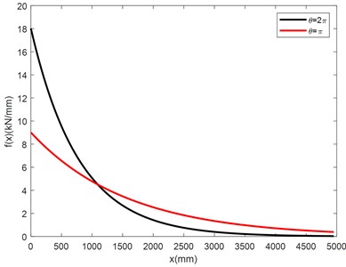
Fig. 6Curves of the internal axial force distributive
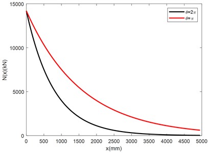
Table 4The values of the parameters α1, β1, α2, β2, ξ1, ζ1, ξ2, ζ2
(mm-1) | (mm-1) | (mm-1) | (mm-1) | ||||
0.003136 | 0.003133 | 0.0008834 | 0.0007816 | –0.1223 | 0.9945 | 0.002385 | 0.00136 |
The coefficients in the expression of Eq. (33) and the coefficients in the expression of Eq. (34) under and have been computed and are listed in Table 5.
Table 5Coefficients in formulars calculating the deflections of the nut column and adjusting beam
(mm) | (mm) | (mm) | (mm) | (mm) | |
–0.7553 | –0.1209 | 0.1367 | –0.8334 | 2.0724 | |
–0.3833 | –0.1208 | 0.1297 | –0.1622 | 1.3644 | |
(mm) | (mm) | (mm) | (mm) | (mm) | |
–0.7487 | 0.01512 | –0.01564 | –0.8359 | 2.0622 | |
–0.3804 | 0.01509 | –0.01557 | –0.1594 | 1.3571 |
Substituting the values of the coefficients in Table 5 to Eqs. (33-34), Eqs. (38-39), Eq. (41) and Eq. (43), we have computed the distributive functions of deflections, internal bending moments and internal shearing forces of the nut column and the adjusting beam of the NCLTS of the Three Gorges shiplift. The curves of the distributive functions are illustrated in Fig. 7.
Fig. 7Curves of the distributive functions of the deflections and internal forces of the NCLTS of the Three Gorges under the different axial interfacial constrain force distributions
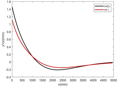
a) Curves of the distributive functions of the deflections of the nut column
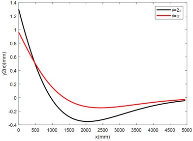
b) Curves of the distributive functions of the deflections of the adjusting beam
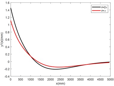
c) Curves of the distributive functions of the bending moments of the nut column
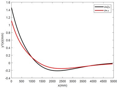
d) Curves of the distributive functions of the deflections of the adjusting beam
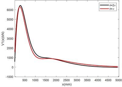
e) Curves of the distributive functions of the shearing forces of the nut column
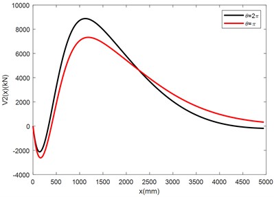
f) Curves of the distributive functions of the shearing forces of the adjusting beam
Table 6 lists the maximum absolute values of the deflections, bending moments and shearing forces of the nut column and adjusting beam of the NCLTSs of the Three Gorges shiplift under two axial interfacial constrain force distributions and . And the relative differences of all the performance parameters under and , which measure the difference of deflection and internal forces under different presumptions of distribution of axial interfacial forces, are also listed in the table. Noticing that the maximum values listed in Table 6 are also the maximum absolute values, so they can be taken as values for design.
Table 6The maximums of the deflection and the internal forces of the NCTM of the Three Gorges shiplift
(mm) | (mm) | (kNm) | (kNm) | (kN) | (kN) | |
1.455 | 1.297 | 2954.8 | 8283.5 | 6452.2 | 8877.6 | |
1.111 | 0.961 | 2870.0 | 5454.0 | 5989.0 | 7328.1 | |
Relative difference | 23.6 % | 25.9 % | 2.9 % | 34.2 % | 7.2 % | 17.5 % |
After obtaining the maximum absolute values of bending moments and shearing forces, we can calculate the normal stresses and shearing forces of the nut column and adjusting beam according to Eqs. (48-51). Table 8 lists the values of related parameters and stresses.
For the design of the NCLTS of the Three Gorges shiplift, the material for the nut columns is G35CrNiMo6-6+QT1, of which the minimum yield strength is 650 N/mm2 [30]. The material for the adjusting beams is Q235D, of which with the thickness of 16-40 mm the minimum yield strength is 225N/mm2 [31]. According to Eqs. (48-51), the maximum allowed normal stress and shearing stress of the nut column are respectively 567 N/mm2and 334 N/mm2, and the maximum allowed normal stress and shearing stress of the adjusting beam are respectively 203 N/mm2 and 119 N/mm2.
It can be seen from Table 7 that the computational normal stress of the nut column for both and and the normal stress of the adjusting beam for are far more than the values obtained by the physical model test. For explaining that, it is necessary to note that “the maximum stress by physical model test” may not be the true maximum stress, as the number of the employed strain gauges is limited and the strain gauges can not cover the whole area of the nut column and the adjusting beam. Nonetheless, it is evidently that both the normal stress and shearing stress of the nut column and adjusting beam of the NCLTS of the Three Gorges shiplift are larger than the values obtained by the physical model test and small than the allowed ones for accidental cases according to the code for shiplift [12], and are in rational range in the views of safety and economy.
Table 7The parameter values involved and the maximum values of the stress of the nut column and the adjusting beam of the NCLTS of the Three Gorges shiplift
Structure | Maximum stress by physical model test (n/mm2) | Maximum stress by computation based on sandwich – type winkler-pasternak defbm (n/mm2) | ||||
Normal stress | Shearing stress | Normal stress | Shearing stress (n/mm2) | |||
Nut column | 70.5 | 15.6 | 218.1 | 212.7 | 20.4 | 18.9 |
Adjusting beam | 71.1 | 41.6 | 124.6 | 82.0 | 61.7 | 50.9 |
3.3. Comments on the results of the calculation
From the figures and tables in the above section, we discovery the following facts about the NCLTS of the Three Gorges shiplift:
1) For each section of the nut column and the adjusting beam, the deflections and internal forces at the end with no centralized external loads (4950 mm) are approximative zeros comparing to the maximum absolute values of the parameters. Therefore, the presumption of infinitesimal is justified.
2) Under the same external axial force and external bending moment, the distribution of the axial interfacial constrain forces affects the distributions of the deflections and internal forces of the nut column and adjusting beam, that is, more centralized the axial interfacial constrain force distribution is related to more centralized the distribution of the internal forces and larger maximum values of the internal forces. The degree of the influence of the centralization of the axial interfacial forces on the internal forces for the nut column and adjusting beam is different. For the nut column, the relative differences of the maximum bending moments with and is only 2.9 %, and the relative differences of the maximum shearing forces is only 7.2 %. For the adjusting beam, the relative differences of the maximum bending moments with and is up to 34.2 %, and the relative differences of the maximum shearing forces with and is 17.5 %. These facts show that the concentration degree of the axial interfacial constrain forces has fewer effects on the internal forces of the nut columns than on the internal forces of the adjusting beams.
3) For the adjusting beam, although the normal stress and shearing stress are relatively large with , and the maximum normal stress (124.6 N/mm2) is a little higer than the one obtained by the finite element method [11], which is 111.35 N/mm2, but they are far smaller than the allowable ones. In the view of safety, adoption of the assumption of the axial interfacial constrain force distribution with is reasonable in design of the NCLTS of the shiplifts using the analytical approach based on sandwich-type Winkler-Pasternak DEFBM proposed in this paper.
4) For the nut column, an interesting fact is noticed that the maximum bending moment of the nut column does not occur at the end on which the concentrated axial forces and external bending moment are applied but a short distance from the end, and the value is not equal to the external bending moment but larger than it. This fact is not in accord with our common sense, by which we will get unsafe design.
5) Both the normal stress and shearing stress of the nut column and adjusting beam of the NCLTS of the Three Gorges shiplift are larger than the values obtained by the physical model test and small than the allowed ones for accidental cases according to the code for shiplift, and are in rational range in the views of safety and economy.
4. Conclusions
The sandwich-type Winkler-Pasternak DEFBM for analysis of the distribution of internal forces and stress calculation of the nut columns and adjusting beams of NCLTSs of shiplifts has been proposed, which supplies the design-oriented computation method. Based on the distribution assumption of the axial interfacial force, the formulas describing the distribution of the deflections and internal forces of the nut columns and adjusting beams have been derived, by which the maximum normal bending moments and shearing forces, as well as the normal stress and shearing stress, have been conveniently calculated.
A case study has been presented to demonstrate the computational procedure and validity of the calculation approach. By analysis of the distribution of the internal forces and the maximum normal stress and shearing stress of the nut column and adjusting beam of the NCLTS of the Three Gorges shiplift, we have obtained following conclusions:
1) The centralization of the distribution of the axial interfacial forces affects the distributions of the internal forces and the magnitudes of the maximum values of the internal forces. More centralization means larger maximum values of the internal forces. This influence is more evidently for the adjusting beams than for the nut columns.
2) The formulars describing the distribution of internal forces of the nut columns and adjusting beams of the shiplifts based on the DEFBM, together with distribution assumption of the axial interfacial forces with ~2, is usable in design of NCLTSs of shiplifts. The assumption of the axial interfacial force distribution with is recommended.
3) The maximum internal bending moment of the nut column is larger than the external bending moment are applied on the loading end of the nut column.
4) The computational results based on the sandwich-type Winkler-Pasternak DEFBM are well matched with the parameters of the structure and layout of the NCLTS of the Three Gorges shiplift, that is, there exists a rationality of the strength design in the views of safety and economy, by the computation results based on the sandwich-type Winkler-Pasternak DEFBM.
5) Considering the fact that the maximum normal stress obtained by the computation based on the sandwich-type Winkler-Pasternak DEFBM is evidently larger than the value obtained by the physical model test, it is suggested that the computational method based on the sandwich-type Winkler-Pasternak DEFBM is applied in the primary design stages, in which large safety margin is a necessity.
References
-
X. Q. Niu and W. B. Song, Design of Ship Locks and Shiplifts. (in Chinese), Beijing, China: China WaterPower Press, 2007.
-
E. Schinkel, Schiffs Lift. (in German), Dortmund, German: Westfälisches Industriemuseum, 2001.
-
X. Q. Niu, D. Tong, and J. D. Wu, Design and Research of Navigation Facilities in High Dams. (in Chinese), Wuhan, China: Changjiang Press, 2022.
-
X. Q. Niu, L. M. Qin, and Q. K. Yu, “The design of gear-rack climbing type ship-lift of Three Gorges project,” (in Chinese), Engineering Sciences, Vol. 13, p. 96, 2011.
-
J. Akkermann, T. Runte, and D. Krebs, “Ship lift at Three Gorges Dam, China – design of steel structures,” Steel Construction, Vol. 2, No. 2, pp. 61–71, Jun. 2009, https://doi.org/10.1002/stco.200910009
-
X. J. Zhao, “Construction summary of Three Gorges Project ship lift,” (in Chinese), Engineering Science, Vol. 15, No. 2, pp. 9–14, 2013.
-
L. K. Liao, H. Zhu, and R. Zhang, “Research and design of the main equipment and structure of Xiangjiaba shiplift,” Engineering Sciences, Vol. 12, p. 81, 2014.
-
W. L. Zheng, “Navigation operation of Three Gorges ship lift: practice and reflection,” (in Chinese), Port and Waterway Engineering, Vol. 600, No. 9, pp. 112–121.
-
Z. F. Sun, C. Gao, and C. Chen, “Operation Management of Xiangjiaba Shiplift,” (in Chinese), Water Power, Vol. 48, No. 5, pp. 115–119, 2022.
-
“Ship lifts: report of a study commission within the framework of permanent technical committee Ⅰ,” Printing Puvrez, Brussels, Belgium, Permanent International Association of Navigation Congresses, 1989.
-
X. Q. Niu, Large Scale Rack and Pinion Shiplifts. (in Chinese), Beijing, China: Science Press, 2021.
-
X. Q. Niu et al., Design Code for Shiplift, GB51177-2016. (in Chinese), Beijing, China: China Planning Press, 2016.
-
“Hydraulic steel structures-part 1: design analysis, DIN 19704-1,” Beuth Verlag Gmbh, Berlin, Germany, Water Practice Standards Committee, 2000.
-
X. L. Jiang, P. Zing, and S. W. Sun, “Study on simulation model experiment of nut column structure of the Three-Gorges ship lift by simulation model experiment,” (in Chinese), Journal of Yangtze River Scientific Research Institute, Vol. 28, No. 1, pp. 61–65, 2011.
-
X. L. Jiang, H. J. Xiao, and S. W. Sun, “Simulation model experiment of partial nut post structure of TGP ship lift,” (in Chinese), Journal of Yangtze River Scientific Research Institute, Vol. 25, No. 4, pp. 85–89, 2008.
-
Z. Li, Y. Liu, and G. X. Zhang, “Study on embedded part load transferring mechanism of safety mechanism for ship-lift of Three Gorges Project,” (in Chinese), Water Resources and Hydropower Engineering, Vol. 51, No. 7, 2020.
-
Y. Liu, “Computational research on mechanism of the load transfer of the long column nut in the Three Gorges Shilift,” Hehai University, Nanjing, China, 2007.
-
A. P. S. Selvaduri, Elastic Analysis of Soil Foundation Interaction. Amsterdam Holland: Elsevier, 1979.
-
A. D. Kerr, “Elastic and viscoelastic foundation models,” Journal of Applied Mechanics, Vol. 31, No. 3, pp. 491–498, Sep. 1964, https://doi.org/10.1115/1.3629667
-
S. C. Dutta and R. Roy, “A critical review on idealization and modeling for interaction among soil-foundation-structure system,” Computers and Structures, Vol. 80, No. 20-21, pp. 1579–1594, Aug. 2002, https://doi.org/10.1016/s0045-7949(02)00115-3
-
A. C. Lamprea-Pineda, D. P. Connolly, and M. F. M. Hussein, “Beams on elastic foundations – A review of railway applications and solutions,” Transportation Geotechnics, Vol. 33, p. 100696, Mar. 2022, https://doi.org/10.1016/j.trgeo.2021.100696
-
S. Akhazhanov, “Analytical solution of beams on elastic foundation,” International Journal of Geomate, Vol. 19, No. 73, pp. 193–200, Sep. 2020, https://doi.org/10.21660/2020.73.51487
-
W. Torback, “Numerical analysis of beams on unilateral elastic foundation,” Archives of Materials Science and Engineering, Vol. 29, No. 2, pp. 109–112, 2008.
-
L. Liao and K. Wang, “The double elastic foundation beam model for analysis of load transfer systems of racks and nut columns in shiplifts,” in Journal of Physics: Conference Series, Vol. 2044, No. 1, p. 012109, Oct. 2021, https://doi.org/10.1088/1742-6596/2044/1/012109
-
E. Winkler, Theory of Elasticity and Strength. Prague, Czechoslovakia: Dominicus Prague, 1867.
-
P. L. Pasternak, “Fundamentals of a new method of analyzing structures on an elastic foundation by means of two foundation constants,” (in Russian), Gosudarstvennoe Izdatelstro Liberaturi po Stroitelstvui Arkhitekture, Moscow, Russia, 1954.
-
Z.-D. Cui, Z.-L. Zhang, L. Yuan, Z.-X. Zhan, and W.-K. Zhang, Design of Underground Structures. Singapore: Springer Singapore, 2020, https://doi.org/10.1007/978-981-13-7732-7
-
F. Y. Liang, Y. C. Li, and M. S. Huang, “Simplified method for laterally loaded piles based on Pasternak double-parameter spring model for foundations,” (in Chinese), Chinese Journal of Geotechnical Engineering, Vol. 35, No. supp. 1, 2013.
-
J. X. Zhan and J. H. Li, “Clearance grouting process test of Three Gorges Project ship lift rack and nut column,” (in Chinese), Engineering Sciences, Vol. 15, pp. 45–49, 2013.
-
“Steel castings. Steel castings for general engineering uses,” DIN EN 10293-2005, Din Deutsches Institut Für Normung E. V., 2005.
-
D. X. Cheng, Handbook of Mechanical Design. (in Chinese), Beijing, China: Chemical Industry Press, 2008.
About this article
This research has been funded by the National Key Research and Development Program of China (2016YFC0402002), and the independent R&D project of Changjiang Institute of Survey Planning Design and Research: Research on Pivot technology for Design of the Safety Ensuring Systems of the Full Balance Vertical Shiplifts (CX2023Z17).
The datasets generated during and/or analyzed during the current study are available from the corresponding author on reasonable request.
The authors declare that they have no conflict of interest.
