Abstract
During gas drilling, the drill string friction is directly related to the safety of drilling and tripping. When the drill string reaches the horizontal section, the friction problem is prominent, which greatly increases the risk and difficulty of trajectory control in the horizontal section. The purpose of this paper is to study the frictional characteristics between drill string and wellbore wall. Firstly, the dynamic mathematical model of drill string in gas drilling is established, a new boundary conditions between wellhead and bottom hole is proposed. Secondly, the governing equation of drill string system is established by using Lagrange equation. Thirdly, the improved Generalized-α method is used to solve the dynamic equation of drill string system. Finally, the effects of weight on bit (WOB) and rotational speed on friction torque of drill string system are analyzed, as well as the effects of different borehole curvature and friction coefficient on friction characteristics of drill string. The findings indicate that as the WOB and rotational speed increase, the lateral motion range and friction torque of the drill string gradually rise; With an increase of borehole curvature and friction coefficient, the friction resistance of the drill string increases obviously. Additionally, it is observed that the average friction resistance of the drill string is greater in horizontal sections compared to vertical and deflecting sections. The average lifting friction on the drill string is less than the lowering friction. Theoretical research plays a crucial role in guiding the optimization of drilling parameters and the implementation of friction reduction.
Highlights
- Utilized Lagrange equations for governing equations; Applied improved Generalized- method for dynamic equations; Integrated multiple factors including well trajectory and friction.
- Identified impact of Weight on Bit (WOB) and rotational speed on friction torque; Noted higher friction in horizontal sections compared to vertical.
- Emphasized controlling WOB and rotational speed for reduced friction; Highlighted benefits for tool longevity and wellbore stability; Provided theoretical foundation for optimized drilling operations.
1. Introduction
With the advancement of drilling technology, gas drilling technology has become widely utilized due to its high drilling efficiency and strong reservoir protection capability. Lowering the drill string into the hole during drilling operations requires applying driving torque at the wellhead, while the top of the drill string experiences a significant hook load in opposite direction to gravity. The drill string is subjected to various loads such as tension, pressure, bending and torsion within the wellbore [1-3]. Exceeding the instability limit of axial force on the drill string results in additional bending moment and increased friction between the drill string and wellbore wall. This can lead to “self-locking” of the drill string, posing a threat to drilling operations [4-5]. The contact between the drill string and wellbore wall not only causes lateral vibration but also generates friction torque leading to torsional vibration. Severe wear of the drilling tools can lead to failure of the drill string and drill bit, as well as wellbore collapse. In addition, excessive frictional energy dissipation in the drill string can prevent the effective transfer of energy to the bit, thereby reducing drilling efficiency. Therefore, it is imperative to study the nonlinear dynamics of the whole drill string system during drilling.
Many scholars have conducted research on the frictional characteristics of drill strings. Wang et al. [6] utilized the Hamilton principle to derive the dynamic equation of a drill string, finding that as axial and torsional excitation increase, the contact strength between the drill string and wellbore gradually increases. Nguyen et al. [7] developed an axial-transversal-torsional dynamic model for drill strings in curved wells, and discussed issues related to limited running depth of drill string based on parameters such as hole trajectory, drilling assembly, and fluid friction; The research findings are significantly relevant for predicting drill string behavior. Lin [8] employed the Karnopp friction model of bit-rock interaction to investigate stick-slip vibration mechanisms of drill strings in vertical wells, revealing that vibration is a key factor causing friction between drill string and wellbore wall. Han [9] applied optimization theory to establish a contact model between drill string and wellbore wall that can accurately identify contact areas. Lian et al. [10] conducted a finite element analysis to investigate the collision and buckling behavior of drill string, demonstrating that the addition of centralizers, control of WOB, and adjustment of rotating speed can effectively reduce collisions between drill string and wellbore wall. Xiao et al. [11] developed a mechanical model for the drill string and optimized its running process from the perspective of tool structure and process flow to minimize running friction. When the drill string comes into contact with the wellbore wall, it will be subjected to corresponding restraining forces, causing the drill string to move within the wellbore. The continuous and intense impact between the drill string and the wellbore increases the probability of wellbore instability. In order to reduce the collision between the drill string and the wellbore, extend the service life of drilling tools, improve the stability of the wellbore, and reduce the risk of drill sticking, it is necessary to analyze the friction mechanism between the drill string and wellbore. SHM systems can monitor the health of components in real time, detect damage and repair it in time, thereby improving component reliability and safety. In the field of oil drilling, the drill string is the core component that connects the surface equipment with the downhole drill bit, and its structural health is directly related to the safety and efficiency of drilling operations. Drilling string is subjected to huge load in complex underground environment, which is prone to fatigue fracture, corrosion, wear and other damages, leading to drilling accidents and downtime. Therefore, SHM on drill string has important engineering application value [12]. M. S. Ismail and N. H. Muhammad studied the buckling behavior of unreinforced cone-round composite shells of low carbon steel under two loading conditions, pointing out possible unsafe factors in ASME Design Code Case 2286-2 under certain conditions. It provides valuable reference data for shell design and safety evaluation. The results show that the position of the defect has a great influence on the shell under combined load, and the concave/pitted defect in the middle of the cylinder is the worst case [13-14].
Although extensive research has been conducted by many scholars on the friction behavior between drill string and wellbore using numerical simulation methods, theoretical analysis methods, and experimental research methods, there are still some shortcomings. Currently, research on the dynamic friction characteristics of drill string is relatively limited, lacking a comprehensive and systematic research framework and methods [15]. The existing finite element model of drillstring dynamics only studies the borehole assembly and the vertical drillstring in shallow boreholes, ignoring the complexity of borehole structure, and without accounting for the mutual coupling between the drillstring system and formation in complex deep horizontal wells, as well as the drillstring system inside. Neglecting these aspects can result in inaccurate model computations. The vibration characteristics of the drillstring only analyzed by using the fixed top boundary condition in most studies, and the feed process along the axis of the drillstring is ignored. Considering the oversimplification of the current dynamic model of the drill string system, this paper addresses the nonlinear contact between the drill string and borehole wall, the discontinuous contact between the bit and rock, and the nonlinear geometric characteristics of both the drill string and bit. We propose a new boundary condition which takes into account the top axial hook load and a delay-dependent boundary condition between the cone bit and rock. Utilizing the finite element method and Hamiltonian principle, the nonlinear dynamic coupling model of the bit-drill string-wellbore-rock system in inclined shafts is established. The Newmark- method is employed to solve the nonlinear dynamic model of the entire drilling string system. In existing research, friction models are often simplified and some complex real-world situations are ignored. Experimental research is constrained by equipment conditions and environment, making it difficult to simulate various friction situations in real drilling, resulting in inaccurate research results. The exploration of the deep-seated mechanisms and influencing factors of drill string friction characteristics is still relatively limited, requiring further in-depth research. Therefore, based on the finite element model of drill string dynamics and the dynamic characteristics of the drill string system, the paper aims to reveal the friction law between the drill string and the wellbore wall and optimize drilling parameters to address these issues. This research is hoped to provide substantial theoretical establishment for the optimization of drilling parameters.
2. Drill string dynamics model
2.1. Beam element model
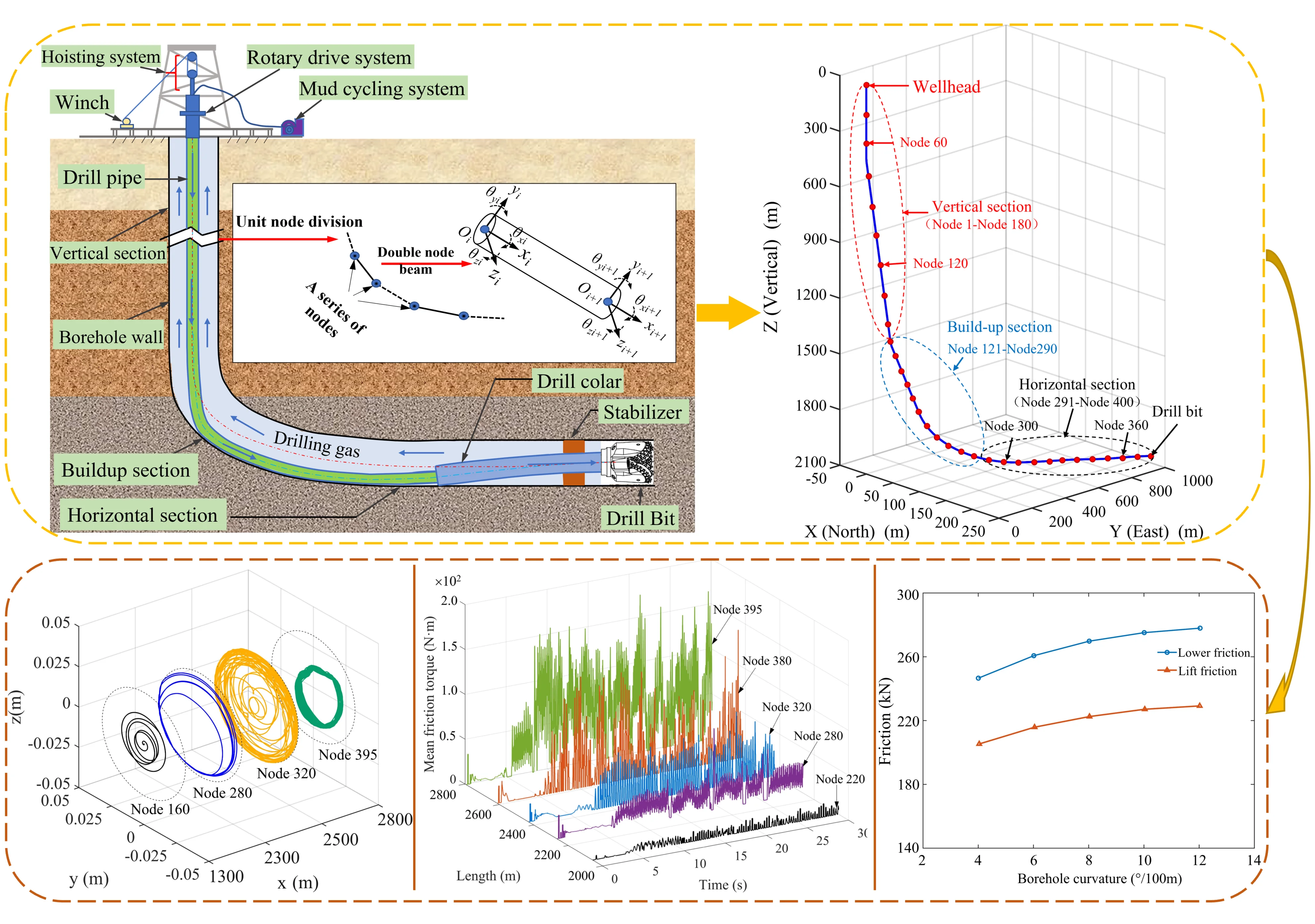
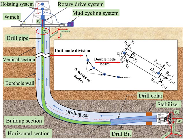
A global coordinate system - is established in Fig. 1 to describe the trajectory of the well, with the origin located at the wellhead, the -axis points due north, the -axis points due east, and the -axis points down to the center of the earth. To more accurately describe the actual state of the drill string in the borehole, a element coordinate system - is instituted on the beam element. The -axis points to the tangential direction of the borehole axis, while the -axis points to thenormal direction of the borehole axis, and the -axis is determined by the right-hand rule [16].
Fig. 1Drill string’s finite element model
A drill string beam element consists of two nodes and twelve degrees of freedom. The three-dimensional motion of the drill string can be represented by the displacement vector of the beam element:
where, subscript represents the th node; , and are linear displacements along the , , and directions, respectively, m; , and is the angular displacement around the , , and axes, respectively, rad; is the transpose of the matrix; is a type function matrix.
Lagrange equation is used to establish the dynamic equation of drill string in element coordinate system [17]:
where, is the kinetic energy, J; is the potential energy, J; represents the reciprocal of the generalized variable with respect to time; is the node force vector of the beam element, N.
The overall kinetic energy of a beam element is comprised solely of translational and rotational kinetic energy, and can be represented as [18]:
where, denotes the length of beam element, m; represents the eccentricity of the beam element, m; represents the density of the beam element, kg/m3; , and represent the translation velocity of the node in the , and axes, respectively, m/s; , and represent rotation speeds around the , , and axes, respectively, rad/s; represents the cross-sectional area of the beam element, m2; represents the speed of the beam unit, r/min; denotes the initial angle between the line connecting the center of gravity of a element to its shape center, relative to the -axis, rad; and represent torsional moment of inertia and transverse moment of inertia per unit length, respectively, kg·m2.
For beam elements subjected to axial load, torsional deformation and bending deformation, their potential energy is expressed as follows [19]:
where, is the elastic modulus of the drill string, GPa; signifies the polar moment of inertia for the cross-sectional geometry of the beam element, m4; is the shear modulus of the drill string, GPa; is the moment of inertia of the beam element cross-section, m4.
The external force vector includes the element gravity, the unbalance force and the contact force between the drill string and the wellbore wall. The density of circulating gas in air drilling is small, and the buoyancy of the air on the drill string can be ignored. Where the unit gravity equivalent nodal force can be expressed as:
where, the gravity component of the beam element per unit length in axis and axis is expressed as and , respectively.
The unbalance force of the drill string unit due to mass eccentricity can be expressed as:
where, and represent the centrifugal force components in the and direction of the beam element, respectively.
The drill string-wellbore wall contact force vector can be expressed as:
where, and represent the components of friction along the -axis and -axis of the beam element respectively; represents the friction torque between the drill string and the wellbore wall.
By substituting Eqs. (3-7) into Eq. (2) and assembling the matrix, the dynamic equation can be expressed as follows:
where, , and are stiffness, mass and damping matrices respectively; , and are generalized acceleration, velocity and displacement vectors, respectively; is resultant force vector.
2.2. Boundary condition
2.2.1. Wellhead boundary conditions
The drill string and top drive are connected at the wellhead, resulting in zero lateral displacement and rotation angle of the first node of the drill string. To simulate the axial hook load of the drillstring, a load is applied to the first node of the model. Additionally, rotational speed is imposed on the first node. The top hook load can be calculated using Hooke’s law:
where, is the axial stretch length of the first element, m; is the initial length of the first beam element, m. Therefore, wellhead boundary conditions can be expressed as:
where, subscripts 1 and represent the first and last node, respectively.
2.2.2. Bottom-hole boundary conditions
The bit diameter matches the hole diameter, this leads to no horizontal movement and turning of the drill bit. Bottom-hole boundary conditions can be expressed as [20]:
where, and represent the axial force and frictional torque of the formation on the bit, respectively.
3. Model solving
3.1. Numerical calculation
The Generalized method is employed to solve the nonlinear dynamic equation of the drill string system, ensuring high accuracy, while the Newton iterative method is utilized for rapid convergence. The solution flow of the drill string system is illustrated in Fig. 2. An approximate solution to the dynamic equation can be obtained through the generalized- method [21-22]:
where, , , , , and are independent dimensionless parameters in the Generalized- method; represents the time step, s; Subscript represents the -th time step.
Fig. 2Solution process of finite element model
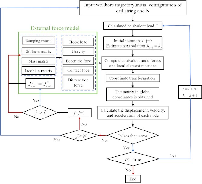
Polynomial expansion of Eq. (12) is performed and higher-order terms are ignored. The displacement iteration expression of the drill string system can be expressed as:
where, is the residual force vector; is the Jacobian matrix and the superscript represents the number of iterations.
Repeat Eq. (15) until the displacement and accumulation tolerance is satisfied:
where, is convergence error.
3.2. System parameter
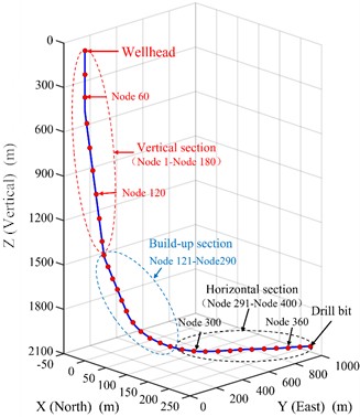
The frictional characteristics of the drill string system were investigated using the air drilling horizontal well model of Jinqian 511-7-H1, located in Sichuan Basin with a vertical depth of 1982 m and a sounding depth of 2844 m. Three-hole size Φ152.4 mm was designed and nitrogen drilling was implemented. The node model of borehole trajectory is shown in Fig. 3. The drill string system comprises drill pipe, heavy weight drill pipe, drill collar, stabilizer and drill bit. The finite element method is used to divide the drill string into several beam elements, with an element length of 6 meters for the deflecting section and horizontal section, and 8.5 meters for the vertical section. To enhance computational efficiency while ensuring unconditional stability in numerical analysis, a time step of 0.0015s is set when solving the finite element model of drill string system dynamics.
The drill string structure parameters are: Φ152.4 mm PDC bit × 9.19 m + Φ120 mm drill collar × 9.19 m + Φ146.1 mm stabilizer ×1.05 m + Φ120 mm drill collar × 17.58 m + Φ101.6 mm heavy weight drill pipe × 283.6 m + Φ101.6 mm drill pipe × 2038.93 m.
Fig. 3Borehole trajectory model of horizontal well
4. Friction characteristic analysis
4.1. Lateral motion characteristics of drill string
The influence of WOB and rotational speed on drill string lateral vibration are illustrated in Fig. 4, where node 160 is located in the vertical section, node 280 is located in the deflecting section, and nodes 320 and 395 are located in the horizontal section. The displacements of each node on the drill string in the and directions increase significantly as the rotational speed increases from 30 r/min to 60r/min, as shown in Fig. 4(a) and (b). The -direction displacement of nodes 160, 280, 320, and 395 increases by 35 %, 12 %, 8 %, and 2 % respectively. Node 160 in the vertical section exhibits no contact with the wellbore wall, while the motion trajectorys of nodes 280 and 320 are concentrated on the lower left of the shaft wall due to the influence of gravity. The larger the node number, the greater the lateral motion range of the drill string. Node 320 executes circular motion around the wellbore at a rotational speed of 60 r/min, leading to an increase in the frequency of contact. Node 395 is located in the position of the stabilizer, since the stabilizer diameter is slightly smaller than the hole diameter, the maximum lateral motion range of node 395 is smaller than that of node 320. The acceleration of the drill string rotation elevates friction between the drill string and the borehole wall, which is unevenly distributed, potentially causing bending or vibration of the drill string. At high rotational speeds, such bending and vibration can expand the contact area between the drill string and the well wall, thereby affecting the trajectory of the drill string [23]. Fig. 4(c) and (d) demonstrate the impact of varying WOB on the lateral displacement of the drill string. The lateral movement range of the drill string increases in correlation with the increase in WOB, while the lateral displacement of the drill string gradually increases as the distance between the node and the bit decreases, similar to the trend of speed change. Therefore, the WOB and the rotational speed should be reduced as much as possible under the premise of meeting the rate of penetration, so as to reduce the contact frequency between the drill string and the wellbore wall, and reduce the drilling friction.
Fig. 4Lateral displacement of drill string with different parameters
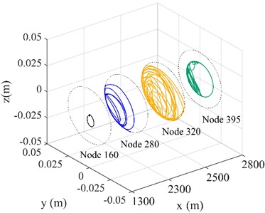
a)= 30 r/min
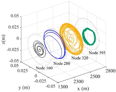
b)= 60 r/min
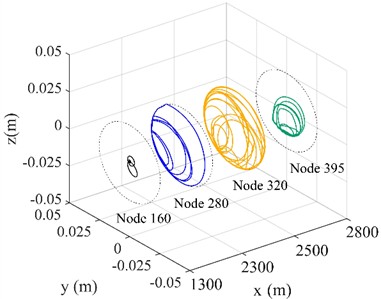
c) WOB = 10 kN
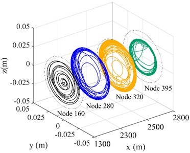
d) WOB = 70 kN
4.2. The influence of borehole curvature on friction of drill string
The influence of borehole curvature on the friction between drill string and wellbore wall is shown in Fig. 5(a). The vertical section is 0-1400 m, the deflecting section is 1400-2000 m, and the horizontal section is 2000-2844 m. As can be seen from Fig. 5(a), with the increase of borehole curvature in the deflecting section, the friction on the drill string gradually increases. The borehole curvature increases from 1°/30 m to 4°/30 m, and the maximum friction force increases by 8 %, and from 7°/30 m to 10°/30 m, the maximum friction force increases by 13 %. When the borehole curvature is 1°/30 m, the friction resistance value of the whole well section is 125 kN. When the borehole curvature is increased to 10°/30 m, the friction resistance increases to 170 kN, and the friction force increases more in the deflecting section than in the horizontal section. Fig. 5(b) shows the curve of average friction with borehole curvature when the drill string is raised and lowered. As can be seen from Fig. 5(b), the average lifting friction on the drill string is less than the average lowering friction on the drill string. With the increase of borehole curvature in the deflecting section, the drag lifted on the drill string and lowered on the drill string gradually increases. When the borehole curvature is 12°/30 m, the lifting friction on the drill string in the whole well section is 225 kN and the lowering friction is 283 kN, which increases 58 kN. Therefore, reasonable drilling parameters should be selected when drill string is lowered to prevent excessive friction. In the design of well structure, the borehole curvature of the hole should be reduced as much as possible, so as to reduce friction and improve drilling efficiency.
Fig. 5Effect of borehole curvature on drill string friction
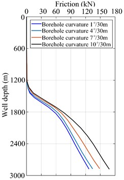
a) Friction of drill string in the whole well section
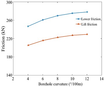
b) Friction of lifting and lowering the drill string
4.3. The influence of friction coefficient on friction of drill string
The influence of friction coefficient on the friction between drill string and wellbore wall is shown in Fig. 6(a). As can be seen from Fig. 6(a), with the increase of friction coefficient, drilling friction increases significantly, and the increase is getting larger. When the friction coefficient increases from 0.2 to 0.3 and 0.4 to 0.5, the friction resistance increases sharply. The relative increase of the former reached 17 kN, up 21 % year-on-year; The latter has a relative increase of 26 kN, an increase of 25 % year-on-year. In addition, the change of friction coefficient has a significant effect on the horizontal drill string, with an average increase of 50 kN per kilometer. Fig. 6(b) shows the curve of average friction with the friction coefficient when the drill string is lifted and lowered. As can be seen from Fig. 6(b), the average lifting friction on the drill string is smaller than that on the lowering friction, because there is less downward pressure when the drill string is lifted. When the friction coefficient is 0.15, the average friction is 259 kN; when the friction coefficient increases to 0.4, the average friction resistance reaches 302 kN, which increases 43 kN. Therefore, in the process of drilling, the cleanliness of the borehole should be increased as much as possible, so as to reduce the drill string friction.
Fig. 6Effect of friction coefficient on drill string friction
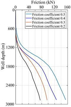
a) Friction of drill string in the whole well section
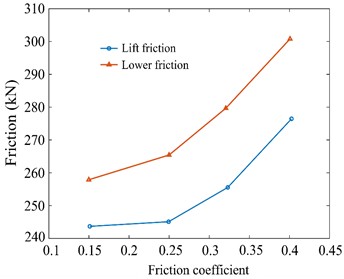
b) Friction of lifting and lowering the drill string
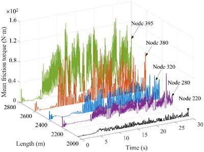
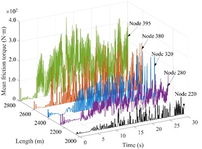
Fig. 7Friction torque of drill string nodes under different WOBs
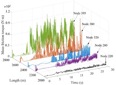
a) WOB = 10 kN
b) WOB = 30 kN
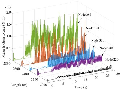
c) WOB = 50 kN
d) WOB = 70 kN
4.4. The drill string friction torque under different WOBs
The drill string friction torque under different WOBs is shown in Fig. 7. Node 220 and 280 are located in the deflecting section, nodes 320 and 380 are located in the horizontal section, and node 395 is located near the bit. According to Fig. 7(a)-(d), It is evident with the increase of WOB, the friction torque between the drill string and wellbore wall significantly increases, and the torque required to drive the drill string to work normally is also larger. When the WOB is 10 kN, the range of friction torque is small, and the maximum friction torque is 90 N∙m; When the WOB is 70 kN, the friction torque fluctuates in the range of 0-2.1 N∙m. An increase in weight on bit causes the drill string to be subjected to a greater axial force, resulting in excessive bending of the drill string in the hole. Drilling string bending increases the area of contact with the wall, which increases friction and torque and increases the risk of wall collapse. Too high weight on bit or too low weight on bit may cause resonance of drill string and increase fatigue damage of drill string [24]. As the distance between node and bit decreases, the friction torque gradually increases, and the average friction torque of drill string in horizontal section is larger than that in vertical section and deflecting section. Therefore, at the deflecting section and horizontal section, it is recommended that the WOB should not exceed 50 kN to extend the service life of the drill string and increase the stability of the wellbore wall [25].
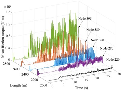
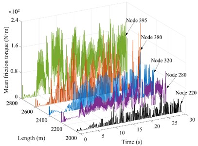
Fig. 8Friction torque of drill string nodes under different rotational speeds
a) = 30 r/min
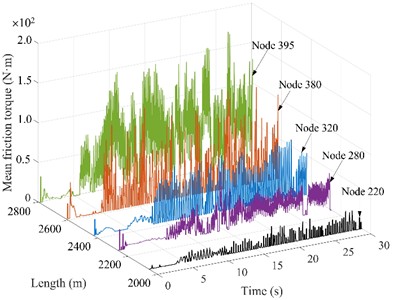
b)= 40 r/min
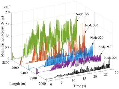
c) = 50 r/min
d)= 60 r/min
4.5. The drill string friction torque under different rotational speeds
The impact of varying rotational speeds on the drill string friction torque is analyzed using a consistent WOB of 30 kN. The amplitude and fluctuation frequency of friction torque increase obviously with the increase of rotation speed, as shown in Fig. 8. When the rotation speed is 30 r/min, 40 r/min, 50 r/min and 60 r/min, the average fluctuation size is 120 N∙m, 150 N∙m, 210 N∙m and 310 N∙m, respectively. This indicates that as rotational speed increases, the likelihood of the drillstring coming into contact with the borehole wall is heightened, which is easy to cause damage to borehole wall. which is consistent with the “the greater lateral vibration displacement and the more frequent the contact between drillstring and wellbore wall” in literature [17]. In addition, the unbalance force generated by the rotation increases with higher rotation speeds, which increases the possibility of the drill string colliding with the wellbore wall. The friction torque of drill string in horizontal section increases significantly, indicating that there is a certain risk of sticking in this section, and the horizontal section should be used as the key well section for anti-wear and drag reduction. Consequently, to minimize the harm caused to drilling tools, it is recommended to choose a speed range of 30-50 r/min.
5. Conclusions
In this paper, the coupling dynamics model of the whole drill string system is established by using the finite element method, considering the horizontal well trajectory, Rayleigh damping, actual boundary conditions, unbalance force, bit-rock friction, drill string-wall friction and other factors. The improved Generalized method is used to solve the drill string dynamic equation. The main conclusions are as follows:
1) With the increase of borehole curvature, the friction of drill string in the whole well section increases gradually, and the friction of lifting and lowering drill string also increases; The friction resistance when lifting the drill string is lower than that when lowering it. The average friction of drill string increases sharply in the deflecting section, and increases relatively slowly after entering the horizontal section.
2) With the increase of the drill string-wellbore wall friction coefficient, the friction of drill string in the whole well section increases significantly; In the process of drilling, the cleanliness of the hole should be increased as much as possible, so as to reduce the friction between the drill string and the wall of the hole.
3) The vertical section experiences minimal friction force and torque; The drill string in the deflecting section and the horizontal section is in low side contact under its own gravity, resulting in greater friction and excessive wear of the drilling string, which is the key well section for anti-wear and drag reduction measures. The drill string-wellbore contact strength increases significantly with high WOB and rotational speed, which is easy to cause stuck drilling and wellbore instability. The recommended speed range is 30 r/min-60 r/min, and the WOB does not exceed 50 kN.
References
-
C. B. Feng, X. L. Jia, S. H. Liu, and X. L. Zhong, “Research progress on stick-slip vibration of drilling string in oil and gas Wells,” (in Chinese), Oil Field Equipment, Vol. 45, No. 11, pp. 78–87, Jan. 2016, https://doi.org/10.3969/j.issn.1001-3482.2016.11.018
-
H. L. S. Monteiro and M. A. Trindade, “Performance analysis of proportional-integral feedback control for the reduction of stick-slip-induced torsional vibrations in oil well drillstrings,” Journal of Sound and Vibration, Vol. 398, pp. 28–38, Jun. 2017, https://doi.org/10.1016/j.jsv.2017.03.013
-
S. Divenyi, M. A. Savi, M. Wiercigroch, and E. Pavlovskaia, “Drill-string vibration analysis using non-smooth dynamics approach,” Nonlinear Dynamics, Vol. 70, No. 2, pp. 1017–1035, Jul. 2012, https://doi.org/10.1007/s11071-012-0510-3
-
D. L. Gao and W. J. Huang, “Research progress of downhole pipe string mechanics and control methods,” Advances in Mechanics, Vol. 51, No. 3, pp. 620–647, Apr. 2021, https://doi.org/10.6052/1000-0992-21-028
-
D. L. Gao, W. J. Huang, and Y. S. Liu, “Research progress on drill string mechanics and casing wear prediction,” (in Chinese), Petroleum Pipes and Instruments, Vol. 6, No. 4, pp. 1–9, Jul. 2020, https://doi.org/10.19459/j.cnki.61-1500/te.2020.04.001
-
B. Wang, Z. Wang, and F. Ren, “Dynamic model and quantitative analysis of stick-slip vibration in horizontal well,” (in Chinese), Shock and Vibration, Vol. 2020, pp. 1–14, Jul. 2020, https://doi.org/10.1155/2020/8831111
-
K.-L. Nguyen et al., “Nonlinear rotordynamics of a drillstring in curved wells: models and numerical techniques,” International Journal of Mechanical Sciences, Vol. 166, p. 105225, Jan. 2020, https://doi.org/10.1016/j.ijmecsci.2019.105225
-
W. Lin, “Research on stick-slip vibration mechanism and experimental technique of drilling string system in horizontal Wells,” (in Chinese), Southwest Petroleum University, Chengdu, 2020.
-
Z. Huang et al., “Investigation of PDC bit failure base onstick-slip vibration analysis of drilling string system plus drill bit,” Journal of Sound and Vibration, Vol. 417, No. 17, pp. 97–109, Mar. 2018, https://doi.org/10.1016/j.isv.2017.11.053
-
M. Kapitaniak, V. Vaziri, J. Páez Chávez, and M. Wiercigroch, “Numerical study of forward and backward whirling of drill-string,” Journal of Computational and Nonlinear Dynamics, Vol. 12, No. 6, pp. 1–7, Nov. 2017, https://doi.org/10.1115/1.4037318
-
Y. Xiao, Q. W. Zong, and R. Li, “Test of floating string technique in long open hole horizontal wells in western Sichuan,” Drilling and Production Technology, Vol. 45, No. 5, pp. 34–38, Nov. 2022, https://doi.org/10.3969/j.issn.1006-768x.2022.05.06
-
A. de Luca, A. Greco, N. Rezazadeh, D. Perfetto, and A. Aversano, “Guided waves propagation in additively manufactured GF30‐PA6 panel,” Macromolecular Symposia, Vol. 413, No. 3, p. 24000, Jun. 2024, https://doi.org/10.1002/masy.202400042
-
M. N. Hazwan et al., “Mode II debonding characterization of adhesively bonded aluminum joints,” Advanced Structured Materials, Vol. 173, pp. 95–107, Mar. 2023, https://doi.org/10.1007/978-3-031-26636-2_9
-
M. S. Ismail, O. Ifayefunmi, and A. H. Mazli, “Combined stability of cone-cylinder transition subjected to axial compression and external pressure,” Thin-Walled Structures, Vol. 157, p. 107102, Dec. 2020, https://doi.org/10.1016/j.tws.2020.107102
-
L. Mao, Q. Zheng, Q. Fu, and J. Zhu, “Dynamic analysis of a drilling string for deepwater riserless drilling with vortex-induced vibration considered,” Ocean Engineering, Vol. 301, p. 117325, Jun. 2024, https://doi.org/10.1016/j.oceaneng.2024.117325
-
H. Wang, “Modeling and analyzing the motion state of bottom hole assembly in highly deviated wells,” Journal of Petroleum Science and Engineering, Vol. 170, pp. 763–771, Nov. 2018, https://doi.org/10.1016/i.petrol.2018.07.005
-
M. Cai, L. Mao, X. Xing, H. Zhang, and J. Li, “Analysis on the nonlinear lateral vibration of drillstring in curved wells with beam finite element,” Communications in Nonlinear Science and Numerical Simulation, Vol. 104, p. 106065, Jan. 2022, https://doi.org/10.1016/j.cnsns.2021.106065
-
T. G. Ritto, C. Soize, and R. Sampaio, “Non-linear dynamics of a drill-string with uncertain model of the bit-rock interaction,” International Journal of Non-Linear Mechanics, Vol. 44, No. 8, pp. 865–876, Oct. 2009, https://doi.org/10.1016/j.ijnonlinmec.2009.06.003
-
H. Zhang, Q. Di, N. Li, W. Wang, and F. Chen, “Measurement and simulation of nonlinear drillstring stick-slip and whirling vibrations,” International Journal of Non-Linear Mechanics, Vol. 125, p. 103528, Oct. 2020, https://doi.org/10.1016/j.ijnonlinmec.2020.103528
-
K. P. Yu, “A new family of generalized‐α time integration algorithms without overshoot for structural dynamics,” Earthquake Engineering and Structural Dynamics, Vol. 37, No. 12, pp. 1389–1409, Oct. 2008, https://doi.org/10.1002/eqe.818
-
A. Ghasemloonia, D. Geoff Rideout, and S. D. Butt, “Analysis of multi-mode nonlinear coupled axial-transverse drillstring vibration in vibration assisted rotary drilling,” Journal of Petroleum Science and Engineering, Vol. 116, pp. 36–49, Apr. 2014, https://doi.org/10.1016/j.petrol.2014.02.014
-
Z. Tao et al., “Analysis of nonlinear vibration of lateral-torsional coupling for drill string in deviated well,” Journal of Vibroengineering, Vol. 26, No. 7, pp. 1584–1599, Nov. 2024, https://doi.org/10.21595/jve.2024.24140
-
Q.-T. Tran et al., “Nonlinear dynamics of directional drilling with fluid and borehole interactions,” Journal of Sound and Vibration, Vol. 462, p. 114924, Dec. 2019, https://doi.org/10.1016/j.jsv.2019.114924
-
X. Liu, N. Vlajic, X. Long, G. Meng, and B. Balachandran, “Nonlinear motions of a flexible rotor with a drill bit: stick-slip and delay effects,” Nonlinear Dynamics, Vol. 72, No. 1-2, pp. 61–77, Dec. 2012, https://doi.org/10.1007/s11071-012-0690-x
-
C. Xiang et al., “Nonlinear dynamics of a drillstring system with PDC bit in curved wells based on the finite element method,” Geoenergy Science and Engineering, Vol. 230, p. 212240, Nov. 2023, https://doi.org/10.1016/j.geoen.2023.212240
About this article

The authors have not disclosed any funding.
The datasets generated during and/or analyzed during the current study are available from the corresponding author on reasonable request.
Dianchen Liu: conceptualization, methodology, software, writing – original draft. Xiao Huang: conceptualization, methodology, software, writing-original draft. Ke Deng: resources, supervision. Pan Fang: resources, supervision, funding acquisition, conceptualization. Hai Yan, Chengxiao Li and Ketao Cai: resources, supervision, funding acquisition, conceptualization.
The authors declare that they have no conflict of interest.
