Abstract
CoCrFeMoNi high entropy alloy coating was prepared on Q235 substrate by plasma cladding method. The phase structure, morphology characteristics, element distribution, microhardness, and wear resistance for this alloy without and with Si doping were investigated by XRD, OM, SEM, EDS, microhardness tester, and friction-wear tester, respectively. The results show that CoCrFeMoNi alloy is composed of a single FCC phase, while Si-containing alloy is composed of FCC main phase and HCP phase. Both alloys have a typical dendritic structure. There is a layer of isotropic fine-grained region near the fusion line, and a columnar crystal region away from the fusion line. After adding Si element, the enrichment of Mo element in the interdendrite region and Co element in the dendrite region significantly decreased, which is related to the Si-containing alloy can provide a liquid environment with longer duration, lower viscosity, and greater fluidity. The change of Cr element enrichment from interdendrite region to dendrite region is the result of comprehensive competition of mixing enthalpy, atomic radius difference, electronegativity, density, and melt flowability between alloying elements. The friction coefficients of the two alloys show a rapid increase first and then gradually stabilize with the increase of time. After adding Si element, the hardness and wear resistance of the alloy are greatly improved, which is mainly related to the increase of the lattice distortion of FCC phase, the formation of high-strength HCP phase and the reduction of internal defects.
Highlights
- After adding Si element, the alloy phase structure is transformed into a dual-phase structure composed of FCC main phase and HCP phase.
- The mixing enthalpy, mixing entropy, Gibbs free energy and atomic radius difference of the two alloys are calculated.
- The main reasons for the improvement of the hardness and wear resistance of the alloy with the addition of Si element are the reduction of internal defects and the generation of high-strength HCP phase.
- After adding Si element, the hardness increases by 29.29 % to 398.42 HV, and its friction coefficient decreases to 0.4455, a decrease of 26.90%.
- The addition of Si element makes the enrichment degree of Mo element in the interdendrite region and Co element in the dendrite region decrease significantly.
1. Introduction
Since the Bronze Age, metal materials have always played an important role in the history of human civilization. With the continuous development of science and technology, traditional metal materials have been difficult to meet the needs of high-performance materials in modern industrial technology under some extreme conditions. High-entropy alloys (HEAs, or multi-principal element alloys) break the traditional alloy design concept of one or two alloying elements as the main component. Due to their excellent performances in strength [1, 2], wear resistance [3, 4], corrosion resistance [5, 6], high and low temperature resistance [7,8], high temperature tempering softening resistance [9, 10], and radiation resistance [11, 12], as well as the ability to form a simple solid solution structure, they have the potential to break through the performance limits of traditional alloys and are considered to be the development direction of the next generation of metal materials [13-15].
CoCrFeMoNi is considered a high entropy alloy system with great development potential [16-18]. The research that has been carried out is mainly focuses on element substitution and proportion control [18,19], high-strength phase doping [20, 21], phase and morphology structure control [22, 23], wear and corrosion resistance [24, 25], process optimization [22, 26], and application expansion [25, 26]. Brito Garcia et al. [18] studied the effect of Ti addition on the microstructure and hardness of CoCrFeMoNi alloy, which is composed of face-centered cubic (FCC), body-centered cubic (BCC), and Laves phases. The addition of Ti refines the alloy grains and increases the hardness from 369HV to 451HV, while reducing the concentration difference of Mo in the dendrite and interdendrite regions. Bogdanov et al. [24] tested the corrosion and electrochemical behavior of the CoCrFeMoNi alloy in chlorine-containing solutions with different pH values by electrochemical and immersion for more than 3000 h. This alloy has excellent corrosion resistance in both neutral and acidic NaCl solutions, and the corrosion rate does not exceed 1 μm/year. After the addition of 0.01 M H2O2 in the acidic solution of NaCl, the corrosion rate is about 21 μm/year. Liu et al. [25] prepared CoCrFeMoNi alloy coating on the surface of 304 stainless steel by argon tungsten arc cladding process. The coating hardness is about 3 times that of the substrate, reaching 585HV. The minimum wear rate is reduced by 58 % compared to the substrate, and it has better passivation film formation ability and pitting resistance than the substrate. Chen et al. [26] prepared CoCrFeMoNi alloy coatings on 45 steels by synchronous ultrasonic impact treatment (UIT) treatment enhanced laser cladding process method. Due to the plastic deformation and high-frequency vibrations caused by UIT, dislocation interactions lead to a recrystallization process at the top region coating. The columnar grains at the top region of the coating transformed into fine equiaxed grains, and grain refinement occurs due to recrystallization. Defects in the coating are effectively eliminated.
Si, as a common HEA addition element, has many excellent properties, such as improving wear and corrosion resistance [27, 28], reducing oxide scale cracking, and enhancing adhesion of oxide scale [29, 30]. Xi et al. [27] prepared FeCoNiCrAl alloy with Si addition by vacuum melting method. The addition of Si elements significantly increased the hardness and wear resistance of the alloy and also reduced the segregation of the alloying elements. Chang et al. [28] prepared Si added AlZrNbTi lightweight refractory HEAs. The addition of Si causes the phase structure to change from a single BCC phase to a BCC matrix phase with Zr5Al3 hexagonal precursor phases. The addition of Si can promote the growth of continuous and dense oxides, which helps to improve the corrosion resistance of the alloy. Guo et al. [29] prepared Si-added TaMoZrTiAl HEAs by arc melting method. The addition of Si element not only promotes the formation of dendritic structure and inhibits the transition from parabolic to linear oxidation kinetics, but also reduces the severe cracking of the oxide scales and improves the adhesion and oxidation resistance of the oxide scales. Li et al. [30] prepared Si added AlCoCrFeNiSi HEAs by vacuum arc melting. The Si containing alloy is mainly composed of BCC phase and Si-rich precipitates. The addition of Si can promote the formation of a single and dense Al2O3 oxide scale, thereby improving the oxidation resistance of the alloy. The addition of excessive Si will cause the formation of easily peelable oxide scale composed of Al2O3 outer layer and mixed oxide inner layer, which is not conducive to the improvement of oxidation resistance. In addition, the addition of Si element can also change the balance between strength and ductility of high entropy alloys, adjust the plastic deformation mechanism, and increase the yield stress [31]. However, there are few reports on the effect of Si addition on CoCrFeMoNi high-entropy alloy coatings (HEACs). In this paper, CoCrFeMoNi and CoCrFeMoNiSi HEACs were prepared on Q235 steel surfaces by plasma cladding. The effects of Si elements addition on their phase structure, morphology characteristics, composition distribution, hardness and wear resistance are discussed in detail, which helps to enrich and improve the theoretical system of CoCrFeMoNi alloy and provide data and theoretical reference for subsequent research of this alloy.
2. Experimental procedures
The raw materials of CoCrFeMoNi and CoCrFeMoNiSi alloys are Co, Cr, Fe, Mo, Ni, and Si powders with a particle size of 200 mesh and a purity higher than 99.5 % (mass fraction). The raw material powder is weighed in equimolar ratios and grinded in a corundum mortar for 30 minutes. The surface oxide layer of Q235 steel is removed using a grinding machine and polished with sandpaper, and then repeatedly rinsed with acetone solution to remove oil and impurities on the surface. The ground raw material powder is mixed with binder and prefabricated on the surface of Q235 substrate. The width of the prefabricated sample is about 3 mm and the height is about 5 m. Then it is placed in the DHG-9123A electrothermal constant temperature drying oven at 80 °C for 2 h. Finally, the plasma cladding was carried out by Hutong LHM-500 digital plasma cladding welding machine. The cladding voltage is 32 V, the current is 100 A, and the moving speed is 1.5 mm/s. The distance between the nozzle and the surface of the workpiece is about 8mm. The cladding process uses high-purity argon gas as protective gas, and the gas flow rate is 1m3/h. The thickness of the coating after cladding is about 1.5 mm. The cladding samples were cut into 10 mm×10 mm×5 mm block samples by DK-M140 wire-cutting electric discharge machine.
The phase structure was carried out by Ultima IV X-ray diffractometer (XRD) (Cu-Kα, scanning speed 10 °/min, working voltage 40 KV, working current 20 mA). The microstructure was analyzed by Hitachi TM-4000 Plus scanning electron microscope (SEM), energy dispersive spectrometer (EDS) and DMM-150C optical microscope (OM). The hardness was measured by HVS-1000 Vickers microhardness tester. The applied load was 0.3 kg, and the holding time was 15 s. The friction and wear test were carried out on the MFT-R4000 reciprocating friction and wear tester. The friction pair was a tungsten steel ball with a diameter of 6 mm, a load of 10 N, a stroke length of 10 mm, and a reciprocating frequency of 5 Hz.
3. Results and discussion
3.1. Phase analysis
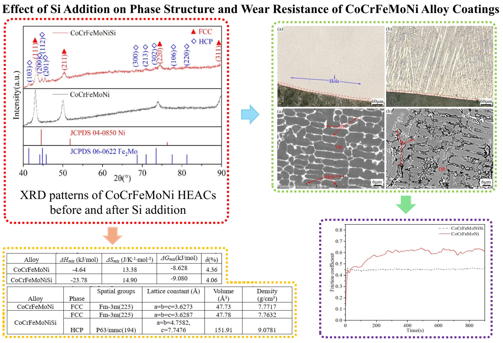
Fig.1 shows the XRD patterns of CoCrFeMoNi HEACs before and after Si addition. It can be seen from Fig.1 that CoCrFeMoNi alloy is composed of a single FCC phase. After the addition of Si element, the alloy phase is transformed into a dual-phase structure of FCC main phase and HCP phase. The diffraction peaks of these two phases are (111), (211), (220), (311), and (103), (200), (112), (201), (300), (213), (302), (106), (220), respectively. Their space group belongs to Fm-3m (225) and P63/mmc (194), respectively. The diffraction peaks of FCC and HCP phase are basically consistent with those of Ni (No. 04-0850) with FCC structure and Fe2Mo (No. 06-0622) with HCP structure from the standard card published by Joint Committee on Powder Diffraction Standards (JCPDS), respectively, but the diffraction peaks of the two phases are obviously shifted.
Fig. 1XRD patterns of CoCrFeMoNi and CoCrFeMoNiSi alloys
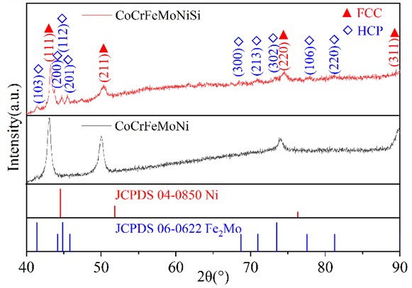
Compared with the above two standard card data, the diffraction peak of CoCrFeMoNi shifts by 1.249° to the small angle direction, and the FCC and HCP phases in the Si-containing alloy shifts by 1.447° and 0.822° to the small angle direction (based on the strongest peak angle of the standard card data corresponding to each phase), respectively. From the Bragg Eq. (1) [32]:
where, is the crystal plane spacing, is the diffraction angle, and is the wavelength. Table 1 shows the characteristic parameters of CoCrFeMoNi alloying elements before and after Si element addition. The diffraction peak shift of CoCrFeMoNi alloy is mainly because the atomic radius of Ni is the smallest, and the substitution of other large atomic radii occupying the corresponding lattice sites will cause the expansion of the crystal cells and the increase of the d value of the crystal plane spacing, which will inevitably lead to the reduction of the diffraction angle, that is, the shift to the small angle direction. After the addition of Si element, the angle of the strongest diffraction peak of FCC phase in this alloy is further shifted from 1.249° to 1.447° in the small angle direction. The reason is that the atomic radius of Si (0.132 nm) is only smaller than that of Mo (0.140 nm), which is much larger than the other four alloying elements. After Si enters and occupies the lattice site of other alloying elements, it is easy to cause cell expansion and increase the crystal plane spacing. Table 2 shows the results of cell refinement of XRD data of CoCrFeMoNi alloy before and after Si addition. As can be seen from Table 2, the lattice constant and unit cell volume of FCC phase increase after the addition of Si elements, which is consistent with the previous analysis that the diffraction peak shifts to the small angle direction.
Table 1Characteristic parameters of CoCrFeMoNi alloy elements before and after Si addition
Element | Melting point (°C) | Atomic radius (nm) | Density (g/cm3) | Crystal structure | Electronegativity |
Co | 1493 | 0.125 | 8.90 | HCP | 1.88 |
Cr | 1907 | 0.128 | 7.19 | BCC | 1.66 |
Fe | 1539 | 0.127 | 7.87 | FCC/BCC | 1.83 |
Mo | 2623 | 0.140 | 10.22 | BCC | 2.16 |
Ni | 1455 | 0.125 | 8.90 | FCC | 1.91 |
Si | 1410 | 0.132 | 2.33 | FCC | 1.90 |
Table 2Crystallographic parameters of CoCrFeMoNi and CoCrFeMoNiSi alloys
Alloy | Phase | Spatial groups | Lattice constant (Å) | Volume (Å3) | Density (g/cm3) |
CoCrFeMoNi | FCC | Fm-3 m (225) | 3.6273 | 47.73 | 7.7717 |
CoCrFeMoNiSi | FCC | Fm-3 m (225) | 3.6287 | 47.78 | 7.7632 |
HCP | P63/mmc (194) | 4.7582, 7.7476 | 151.91 | 9.0781 |
In addition, it can be seen from Fig. 1 that the phase structure of CoCrFeMoNi alloy before and after Si addition has changed from a single FCC phase to a dual-phase structure of FCC main phase and HCP phase. No complex intermetallic compounds are generated, which is mainly related to the high mixing entropy of this alloy. According to Gibbs' free energy law (Eqs. (2-6)) [33]:
where is the gas constant, and are the molar percentages of the components and , respectively, and . When , the mixed entropy of the system reaches its maximum. is the number of alloy components, is the interaction parameter between components and . is the A-B binary mixing enthalpy calculated by the Miedema model [34](see Table 3). is the thermodynamic temperature. From Eq. (6), the larger the mixing entropy, the more beneficial it is to reduce the Gibbs free energy of the alloy, which is conducive to inhibiting the trend of ordering and segregation of the alloy [33]. The mixing entropy, mixing enthalpy and Gibbs free energy of CoCrFeMoNi alloy before and after the addition of Si elements are calculated from Eqs. (2)-(6), as shown in Table 4. According to the Hume-Ruthery rule, the atomic radius difference can be expressed as:
where is the atomic radius of component , and is the average atomic radius of each component of the alloy. The atomic radius difference between alloying elements (see Table 3) and the atomic radius difference of CoCrFeMoNi alloy before and after the addition of Si element (see Table 4) are calculated by the Eqs. (7) and (8). According to the - phase formation rule[35],when 6.6 % and –25 kJ/mol 5kJ/mol, the multi-principal alloy is easy to form the solid solution phase structure of single-phase FCC, FCC+BCC dual-phase and single-phase BCC. As can be seen from Table 4, δ and of the two alloys are 4.36 % and –8.628 kJ/mol, and 4.06 % and –9.080 kJ/mol, respectively, which are in accordance with the formation rules of - phase. In addition, HCP phase is formed in the alloy after the addition of Si element, which is attributed to the change in the electronic structure and atomic interaction of the alloy after adding Si element, and the decrease in its stacking fault energy (SFE) [36]. In the early stage of deformation, dislocations move and interact with each other in the lattice to form stacking faults. With the increase of Si content, the probability of stacking faults increases significantly, and the stacking faults and dislocation density accumulated in the alloy also increase. The atomic mismatch degree in the alloy increases with increasing Si content, which leads to an increase in the friction force between Shockley partial dislocations, and a corresponding increase in the difficulty of cross-slip of spiral dislocations. This makes the dislocation more inclined to plane slip, and provides favorable conditions for the formation of twins. When the deformation reaches the critical strain, mechanical twins will be formed in the alloy. The critical stress that activates the twin is proportional to the magnitude of the stacking fault energy. Because the stacking fault energy decreases with the increase in Si content, the critical stress value of twinning also decreases. When the critical stress is overcome, the twins begin to form and grow, eventually leading to the phase transformation from FCC to HCP. When the stacking fault density is high enough, that is, when the interlayer spacing on the adjacent {1 1 1} planes is reduced to the atomic scale, the FCC structure in the local region may transform into the HCP structure through the periodic arrangement of stacking faults (e.g., ABCABCA...→ABABAB...) [36, 37]. This phase transformation process is closely related to the movement of dislocations, the formation of twins, and the expansion of stacking faults, which has been confirmed in many studies [31, 36, 37]. The formation of HCP phase increases the dislocation density and phase interface of the alloy. Due to the multiple obstacles such as phase boundaries, stacking faults and twin boundaries, the movement of dislocations will be significantly hindered, thereby improving the strength of the alloy [37, 38].
Table 3Mixing enthalpy (kJ/mol) and atomic radius difference (%) of any two components in CoCrFeMoNi and CoCrFeMoNiSi alloys
Element | Co | Cr | Fe | Mo | Ni | Si | ||
(kJ/mol) | Co | − | 1.186 | 0.794 | 5.660 | 0.000 | 2.724 | (%) |
Cr | –4 | − | 0.392 | 4.478 | 1.186 | 1.538 | ||
Fe | –1 | –1 | − | 4.869 | 0.794 | 1.931 | ||
Mo | –5 | 0 | –2 | − | 5.660 | 2.941 | ||
Ni | 0 | –7 | –2 | –7 | − | 2.724 | ||
Si | –38 | –37 | –35 | –35 | –40 | − |
Table 4Thermodynamic parameters of CoCrFeMoNi and CoCrFeMoNiSi alloys
Alloy | (kJ/mol) | (J/K-1∙mol-1) | (kJ/mol) | (%) |
CoCrFeMoNi | –4.64 | 13.38 | –8.628 | 4.36 |
CoCrFeMoNiSi | –23.78 | 14.90 | –9.080 | 4.06 |
3.2. Microstructure analysis
Fig. 2 is the metallographic photos of the cross section of CoCrFeMoNi alloy coatings before and after Si addition. From Fig. 2, there is a layer of isotropic fine grain zone near the fusion line of both alloys, and the area away from the fusion line is a columnar grain zone. The formation of fine-grained zone is mainly due to their close connection with the unmelted substrate, which can take away a large amount of heat through thermal conduction and generate a large degree of undercooling, resulting in rapid nucleation of the melt in this area and the formation of a fine equiaxed grain zone. The columnar crystal zone is located far away from the fusion line and flows through the heated area when dissipating heat through thermal conduction towards the substrate, resulting in a relatively gentle temperature gradient. Due to the maximum temperature gradient obtained in the opposite direction of heat flow, the growth of columnar crystal zone exhibits significant directionality. In addition, there are a few holes in the cladding layer area of CoCrFeMoNi alloy. No obvious hole defects are observed in the alloy with Si addition. This is mainly because the melting point and density of Si are the smallest among all alloying elements, which can provide a liquid environment with longer solidification time, lower viscosity, and greater fluidity for the melt solidification process. It helps gas molecules or ions in the melt to quickly escape and be filled and welded by the unmelted liquid alloy, thereby reducing the probability of defect formation, which is consistent with the situation reported in the literature [39-41].
Fig. 2Metallographic photos of the cross section of CoCrFeMoNi: a) and CoCrFeMoNiSi; b) alloy coatings
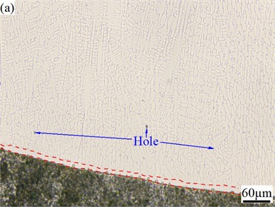
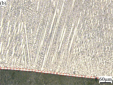
Fig. 3SEM images of CoCrFeMoNi (a) and CoCrFeMoNiSi (b) alloys
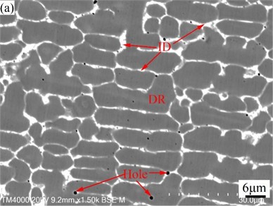
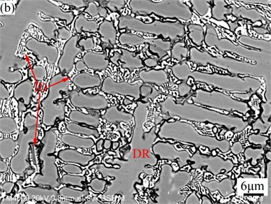
Fig. 3 shows SEM images of CoCrFeMoNi alloy before and after the addition of Si element. From Fig. 2 and Fig. 3, it can be seen that both alloys have typical dendritic structures. Table 5 is the EDS analysis results of CoCrFeMoNi alloy before and after the addition of Si element. In order to better understand the segregation of the same element in the dendrite (DR) and interdendrite (ID) regions, the segregation coefficient is introduced [32]:
where is the dendrite region concentration of an element, and is the interdendrite region concentration of the element. When , 0 indicates that there is no concentration difference between the dendrite and the interdendrite regions, that is, the segregation coefficient is 0. When the concentration difference between and is larger, the value of / or / is smaller, and the value of / or / is larger, that is, the absolute value of is larger, indicating that the segregation of dendrite and interdendrite region is larger. When the value is positive, it means that the concentration of the same element in the dendrite region is higher than that in the interdendrite region, that is, it is enriched in the dendrite region. When the value is negative, it means that the concentration of the same element in the dendrite region is lower than that in the interdendrite region, that is, it is enriched in the interdendrite region. According to Table 5, Mo element in CoCrFeMoNi alloy is mainly enriched in the interdendrite region, while Co element is mainly enriched in the dendrite region. The distribution of Cr, Fe, and Ni is relatively uniform. After adding Si element, Si element is enriched in the interdendrite region, while the enrichment degree of Mo element in the interdendrite region and Co element in the dendrite region decreased significantly. The enrichment of Cr element changed from the original enrichment in the interdendrite region to the enrichment in the dendrite region. The enrichment of Si in the interdendrite region is mainly due to the lowest melting point of Si among all alloying elements (see Table 1), and its precipitation mainly occurs in the interdendrite region in the later stage of solidification. The decrease of Mo and Co enrichment is due to the high fluidity of Si-containing alloy melt, which can improve the diffusion rate and reduce diffusion resistance of each alloying elements. This is conducive to the full diffusion of each alloying element, so the enrichment degree of Mo and Co is reduced. The change of the Cr enrichment region is due to the fact that the melting point of Cr in the alloying element is second only to Mo. In order to reduce the nucleation resistance of Cr during precipitation, it is easy to use the surface of the precipitated Mo solid particles as the substrate for heterogeneous nucleation, so the enrichment region is similar to Mo. Cr only has a non-negative mixing enthalpy with Mo (see Table 3), and has smaller differences in atomic radius, density, and electronegativity with Fe, Co, and Ni (see Table 1), which helps the full diffusion of Cr element in the Si-containing alloy melt with higher fluidity and makes it easier to enrich in the dendrite regions dominated by Fe, Co, and Ni.
Table 5EDS analysis results of CoCrFeMoNi and CoCrFeMoNiSi alloys (at %)
Alloy | Region | Co | Cr | Fe | Mo | Ni | Si |
CoCrFeMoNi | Nominal | 20.00 | 20.00 | 20.00 | 20.00 | 20.00 | – |
DR | 16.30 | 20.28 | 36.65 | 7.69 | 19.08 | – | |
ID | 13.72 | 21.09 | 33.88 | 13.38 | 17.93 | – | |
K | 15.83 | –3.84 | 7.56 | –42.53 | 6.03 | – | |
CoCrFeMoNiSi | Nominal | 16.67 | 16.67 | 16.67 | 16.67 | 16.67 | 16.67 |
DR | 11.59 | 10.9 | 44.83 | 9.45 | 18.02 | 5.21 | |
ID | 10.9 | 8.55 | 41.62 | 14.19 | 16.81 | 7.93 | |
K | 5.95 | 21.56 | 7.16 | –33.40 | 6.71 | –34.30 |
3.3. Hardness and wear resistance
Fig. 4 shows the curve of friction coefficient with time for CoCrFeMoNi HEACs before and after the addition of Si element. After adding Si element, the friction coefficient of the coating decreased from 0.6094 to 0.4455, which decreased by 26.90 %.
Fig. 4Relationship between friction coefficient and time of CoCrFeMoNi and CoCrFeMoNiSi coatings
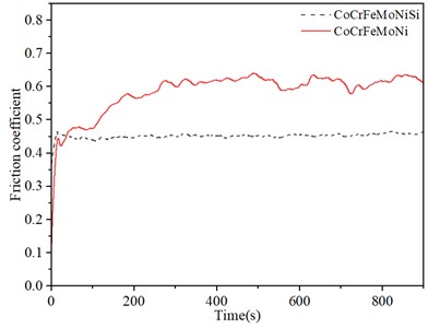
As shown in Fig. 4, the friction coefficients of the two alloys increase rapidly and then gradually stabilize with the increase of time. The friction coefficients of the alloys before and after the addition of Si element are 0.6094 and 0.4455, respectively. This is mainly because in the initial stage of friction, it is in the running-in stage. With the extension of friction time, the initial line contact changes to surface contact, and the surface wear marks of the sample gradually deepen. The hindering effect of the friction pair is strengthened, resulting in an increase of friction resistance and friction coefficient. As the friction continues, the exposed fresh surface will be rapidly oxidized due to the heat generated by high-speed friction. The generated oxide particles adhere to the friction surface to play a lubricating role, and the amplitude of the friction coefficient gradually decreases and tends to be stable. In addition, the hardness of CoCrFeMoNi and CoCrFeMoNiSi coatings are 308.17 HV and 398.42 HV, respectively. After adding Si element, the hardness of the coating increased by 29.29 %. Generally, the hardness is negatively correlated with the friction coefficient [42], that is, the greater the hardness of the sample, the smaller the friction coefficient. After adding Si element, the increase in hardness and the decrease in friction coefficient are mainly related to the increase of the lattice distortion of FCC phase (such as the increase of diffraction peak shift angle) and the formation of high-strength HCP phase [32, 43] in Si containing alloys (see Fig. 1), as well as the reduction of internal defects (such as holes) (see Figs. 2 and 3). The main reason why the phase transformation from FCC to HCP can improve the wear resistance of CoCrFeMoNiSi alloy is that the HCP structure has a higher hardness and a lower number of slip systems than the FCC structure, thereby reducing the plastic deformation and wear during the friction process. The FCC structure has higher symmetry and more slip systems (12), which means that the dislocations in the FCC crystals can move in multiple directions when the force is applied, which can easily lead to plastic deformation and wear. In contrast, the HCP structure has lower symmetry and fewer slip systems Eq. (3), and the direction of dislocation movement is restricted. Therefore, HCP crystals are more difficult to undergo plastic deformation than FCC crystals. This restriction allows the HCP structure to better resist deformation when subjected to wear, thereby improving wear resistance [44]. Montero-Ocampo [45] found that the wear resistance of Co-27Cr-5Mo-0.05C alloy was significantly improved after the transformation of FCC phase to HCP phase, and pointed out that this was mainly due to the reduction of lattice defects by the formation of the HCP phase, which reduced the dissolution rate of the material and the possibility of crack extension.
4. Conclusions
1) CoCrFeMoNi high entropy alloy coating with a single FCC phase structure was successfully prepared on Q235 substrate by plasma cladding method. After adding Si element, the alloy phase structure is transformed into a dual-phase structure composed of FCC main phase and HCP phase. Their space group, lattice structure, cell volume and density are Fm-3m (225), 3.6287 Å, 47.78 Å3, 7.7632 g/cm3, and P63/mmc (194), 4.7582 Å, 7.7476 Å, 151.91 Å3, 9.0781 g/cm3, respectively. The mixing enthalpy, mixing entropy, Gibbs free energy and atomic radius difference of CoCrFeMoNi alloy before and after adding Si element are –4.64 kJ/mol, 13.38 J/K-1∙mol-1, –8.628 kJ/mol, 4.36 %, and –23.78 kJ/mol, 14.90 J/K-1∙mol-1, –9.080 kJ/mol, 4.06 %, respectively.
2) CoCrFeMoNi and CoCrFeMoNiSi alloys have typical dendritic structures. In CoCrFeMoNi alloy, Mo is mainly enriched in the interdendrite region, Co is mainly enriched in the dendrite region, and the distribution of Cr, Fe and Ni is relatively uniform. The addition of Si element makes the enrichment degree of Mo element in the interdendrite region and Co element in the dendrite region decrease significantly, while Cr element changes from the original enrichment in the interdendrite region to the enrichment in the dendrite region.
3) The hardness and friction coefficient of CoCrFeMoNi HEACs are 308.17 HV and 0.6094, respectively. After adding Si element, the hardness increases by 29.29 % to 398.42 HV, and its friction coefficient decreases to 0.4455, a decrease of 26.90 %. The main reasons for the improvement of the hardness and wear resistance of the alloy with the addition of Si element are the reduction of internal defects and the generation of high-strength HCP phase. The improvement of wear resistance of alloy coatings helps to enhance the service life, reliability and performance of mechanical parts, which is expected to show great application potential in metallurgy, mining, automobile manufacturing, aerospace, and other fields.
References
-
H. Wang et al., “Multifunctional high entropy alloys enabled by severe lattice distortion,” Advanced Materials, Vol. 36, No. 17, p. 23054, Nov. 2023, https://doi.org/10.1002/adma.202305453
-
H. Ren et al., “Introduction of rare-earth element Sc in alloy design to modify wear features of dual-phase high-entropy alloy,” Rare Metals, Vol. 43, No. 2, pp. 817–828, Nov. 2023, https://doi.org/10.1007/s12598-023-02412-y
-
J. Hu, K. Yang, Q. Wang, Q. C. Zhao, Y. H. Jiang, and Y. J. Liu, “Ultra-long life fatigue behavior of a high-entropy alloy,” International Journal of Fatigue, Vol. 178, p. 108013, Jan. 2024, https://doi.org/10.1016/j.ijfatigue.2023.108013
-
D. Kumar, “Recent advances in tribology of high entropy alloys: A critical review,” Progress in Materials Science, Vol. 136, p. 101106, Jul. 2023, https://doi.org/10.1016/j.pmatsci.2023.101106
-
J.-T. Ren, L. Chen, H.-Y. Wang, and Z.-Y. Yuan, “High-entropy alloys in electrocatalysis: from fundamentals to applications,” Chemical Society Reviews, Vol. 52, No. 23, pp. 8319–8373, Nov. 2023, https://doi.org/10.1039/d3cs00557g
-
M. Ma et al., “Effect of Mn doping on microstructure and corrosion behavior of CoCuNiTi high-entropy alloy coatings,” Crystals, Vol. 15, No. 1, p. 29, Dec. 2024, https://doi.org/10.3390/cryst15010029
-
C. Shen et al., “Evolution of ductile L12 phase in (FeCoNi)86-Al7Ti7 high-entropy alloy aging at various temperatures and its strengthening mechanism,” Journal of Alloys and Compounds, Vol. 1010, p. 177729, Jan. 2025, https://doi.org/10.1016/j.jallcom.2024.177729
-
Y. Wu et al., “Relationship between the unique microstructures and behaviors of high-entropy alloys,” International Journal of Minerals, Metallurgy and Materials, Vol. 31, No. 6, pp. 1350–1363, May 2024, https://doi.org/10.1007/s12613-023-2777-4
-
O. K. Temesi, A. Karacs, N. Q. Chinh, and L. K. Varga, “Thermal softening measurements of refractory high-entropy alloys,” Materials, Vol. 17, No. 23, p. 5718, Nov. 2024, https://doi.org/10.3390/ma17235718
-
J. Pang et al., “A ductile Nb40Ti25Al15V10Ta5Hf3W2 refractory high entropy alloy with high specific strength for high-temperature applications,” Materials Science and Engineering: A, Vol. 831, p. 142290, Jan. 2022, https://doi.org/10.1016/j.msea.2021.142290
-
F. Liu, P. Liaw, and Y. Zhang, “Recent progress with BCC-structured high-entropy alloys,” Metals, Vol. 12, No. 3, p. 501, Mar. 2022, https://doi.org/10.3390/met12030501
-
B. Wang, C. Yang, D. Shu, and B. Sun, “A review of irradiation-tolerant refractory high-entropy alloys,” Metals, Vol. 14, No. 1, p. 45, Dec. 2023, https://doi.org/10.3390/met14010045
-
G. Cao et al., “Liquid metal for high-entropy alloy nanoparticles synthesis,” Nature, Vol. 619, No. 7968, pp. 73–77, Jul. 2023, https://doi.org/10.1038/s41586-023-06082-9
-
S. Bolar, Y. Ito, and T. Fujita, “Future prospects of high-entropy alloys as next-generation industrial electrode materials,” Chemical Science, Vol. 15, No. 23, pp. 8664–8722, Jun. 2024, https://doi.org/10.1039/d3sc06784j
-
H. Ren et al., “A Hf-doped dual-phase high-entropy alloy: phase evolution and wear features,” Rare Metals, Vol. 43, No. 1, pp. 324–333, Nov. 2023, https://doi.org/10.1007/s12598-023-02410-0
-
F. Yoosefan, A. Ashrafi, and S. M. Monir Vaghefi, “Corrosion and tribological behavior of CoCrFeMoNi high-entropy alloys as a potential vascular implant material,” Journal of Alloys and Compounds, Vol. 976, p. 172964, Mar. 2024, https://doi.org/10.1016/j.jallcom.2023.172964
-
B.-L. An, P.-C. Zhang, Z.-R. Cao, C. Zhang, and L. Liu, “Achieving excellent soft-magnetic properties in CoFeAlMnCr high entropy alloy by in-situ additive manufacturing,” Scripta Materialia, Vol. 252, p. 116282, Nov. 2024, https://doi.org/10.1016/j.scriptamat.2024.116282
-
S. J. Brito-Garcia, J. C. Mirza-Rosca, C. Jimenez-Marcos, and I. Voiculescu, “Impact of Ti Doping on the microstructure and mechanical properties of CoCrFeMoNi high-entropy alloy,” Metals, Vol. 13, No. 5, p. 854, Apr. 2023, https://doi.org/10.3390/met13050854
-
L. E. Geambazu, C. M. Cotruţ, F. Miculescu, and I. Csaki, “Mechanically alloyed CoCrFeNiMo0.85 high-entropy alloy for corrosion resistance coatings,” Materials, Vol. 14, No. 14, p. 3802, Jul. 2021, https://doi.org/10.3390/ma14143802
-
R. Furushima and H. Hyuga, “Fabrication of TiC-CoCrFeMoNi composites through various powder processes,” International Journal of Refractory Metals and Hard Materials, Vol. 103, p. 105776, Feb. 2022, https://doi.org/10.1016/j.ijrmhm.2021.105776
-
S. Brito-García, C. Jiménez-Marcos, J. Mirza-Rosca, and I. Voiculescu, “An investigation of elastic modulus in Zr doped CoCrFeMoNi HEA by three-point bending,” Microscopy and Microanalysis, Vol. 29, No. Supplement_1, pp. 1527–1528, Jul. 2023, https://doi.org/10.1093/micmic/ozad067.786
-
F. Yoosefan, A. Ashrafi, and S. M. M. Vaghefi, “Enhanced mechanical and corrosion properties of cold-rolled CoCrFeMoNi high-entropy alloy, as a proposed material for vascular stents,” Materials Characterization, Vol. 205, p. 113343, Nov. 2023, https://doi.org/10.1016/j.matchar.2023.113343
-
N. Liu, Q. Zhou, M. Xu, M. Niu, P. Zhou, and P. Guo, “Evolution in microstructure, properties of the laser cladding CoCrFeMoNi coatings at different annealing temperatures,” Materials Science and Technology, Vol. 39, No. 17, pp. 2782–2791, Dec. 2023, https://doi.org/10.1080/02670836.2023.2225904
-
R. I. Bogdanov et al., “Corrosion and electrochemical behavior of CoСrFeNiMo high-entropy alloy in acidic oxidizing and neutral chloride solutions,” Materials Chemistry and Physics, Vol. 295, p. 127123, Feb. 2023, https://doi.org/10.1016/j.matchemphys.2022.127123
-
N. Liu, Z. Lan, L. Liu, J. Dou, P. Guo, and X. Wang, “Optimizing 304 stainless steel surface performance with CoCrFeMoNi high-entropy alloy coating via gas tungsten arc cladding,” Journal of Materials Engineering and Performance, Vol. 32, No. 20, pp. 9114–9120, Jan. 2023, https://doi.org/10.1007/s11665-022-07781-6
-
Z. Chen et al., “Synchronous ultrasonic impact assisted laser cladding CoCrFeNiMo high entropy alloy coating: Microstructure and wear property,” Tribology International, Vol. 201, p. 110207, Jan. 2025, https://doi.org/10.1016/j.triboint.2024.110207
-
R. Xi and Y. Li, “Influence of Si content on the microstructure, wear resistance, and corrosion resistance of FeCoNiCrAl0.7Cu0.3Six high entropy alloy,” Coatings, Vol. 14, No. 10, p. 1309, Oct. 2024, https://doi.org/10.3390/coatings14101309
-
Y. Chang et al., “Effect of Si on the corrosion resistance of AlZrNbTi lightweight refractory high-entropy alloys in acidic environment,” Corrosion Science, Vol. 238, p. 112377, Sep. 2024, https://doi.org/10.1016/j.corsci.2024.112377
-
Y. Guo, J. Peng, S. Peng, F. An, W. Lu, and Z. Li, “Improving oxidation resistance of TaMoZrTiAl refractory high entropy alloys via Nb and Si alloying,” Corrosion Science, Vol. 223, p. 111455, Oct. 2023, https://doi.org/10.1016/j.corsci.2023.111455
-
Y. Li, P. Zhang, J. Zhang, Z. Chen, and B. Shen, “Oxidation behavior of AlCoCrFeNiSi high-entropy alloys at 1100 ℃,” Corrosion Science, Vol. 190, p. 109633, Sep. 2021, https://doi.org/10.1016/j.corsci.2021.109633
-
D. Wei et al., “Si-addition contributes to overcoming the strength-ductility trade-off in high-entropy alloys,” International Journal of Plasticity, Vol. 159, p. 103443, Dec. 2022, https://doi.org/10.1016/j.ijplas.2022.103443
-
M. X. Ma, D. C. Zhu, Z. X. Wang, S. Z. Li, and C. Dong., “Effect of Zr addition on microstructure and wear properties of CoCrCuFeMn high-entropy alloy.,” Advanced Engineering Sciences, Vol. 53, No. 6, pp. 204–210, 2021, https://doi.org/10.15961/j.jsuese.202100067
-
M. X. Ma, Z. X. Wang, C. Liang, J. C. Zhou, D. L. Zhang, and D. C. Zhu., “Effect of CeO2 doping on microstructure, friction and wear properties of AlCoCrCuFe high-entropy alloys.,” Journal of Materials Engineering, Vol. 47, No. 7, pp. 106–111, 2019, https://doi.org/10.11868/j.issn.1001-4381.2017.001519
-
A. Takeuchi and A. Inoue, “Classification of bulk metallic glasses by atomic size difference, heat of mixing and period of constituent elements and its application to characterization of the main alloying element,” Materials transactions, Vol. 46, No. 12, pp. 2817–2829, Jan. 2005, https://doi.org/10.2320/matertrans.46.2817
-
Y. Zhang et al., “Guidelines in predicting phase formation of high-entropy alloys,” MRS Communications, Vol. 4, No. 2, pp. 57–62, Jun. 2014, https://doi.org/10.1557/mrc.2014.11
-
K. Lin, S.-C. Chen, H.-C. Lin, and H.-W. Yen, “Enhancement in mechanical properties through an FCC-to-HCP phase transformation in an Fe-17.5Mn-10Co-12.5Cr-5Ni-5Si (in at%) medium-entropy alloy,” Journal of Alloys and Compounds, Vol. 898, p. 162765, Mar. 2022, https://doi.org/10.1016/j.jallcom.2021.162765
-
H. Chang et al., “Novel Si-added CrCoNi medium entropy alloys achieving the breakthrough of strength-ductility trade-off,” Materials and Design, Vol. 197, p. 109202, Jan. 2021, https://doi.org/10.1016/j.matdes.2020.109202
-
M. Ma et al., “Microstructure and wear behavior of AlxCoCuNiTi (x = 0, 0.4, and 1) high-entropy alloy coatings,” Metals, Vol. 14, No. 11, p. 1280, Nov. 2024, https://doi.org/10.3390/met14111280
-
Z.-X. Zhu et al., “Effects of Cu/Si on the microstructure and tribological properties of FeCoCrNi high entropy alloy coating by laser cladding,” Wear, Vol. 512-513, p. 204533, Jan. 2023, https://doi.org/10.1016/j.wear.2022.204533
-
T. Lin, M. Feng, G. Lian, H. Lu, C. Chen, and X. Huang, “Effects of Si content on the microstructure and properties of CoCrFeMnNiSix high-entropy alloy coatings by laser cladding,” Materials Characterization, Vol. 216, p. 114246, Oct. 2024, https://doi.org/10.1016/j.matchar.2024.114246
-
M. Ma et al., “Microstructure and wear and corrosion resistance of CoCrFeMoNiSix (x = 0.25, 0.50, 0.75) HEACs prepared by plasma cladding,” Crystals, Vol. 15, No. 2, p. 123, Jan. 2025, https://doi.org/10.3390/cryst15020123
-
M. O. A. Mokhtar, “The effect of hardness on the frictional behaviour of metals,” Wear, Vol. 78, No. 3, pp. 297–304, Jun. 1982, https://doi.org/10.1016/0043-1648(82)90240-x
-
L. X. Wang et al., “The design of appropriate Si content overcomes the strength-ductility trade-off in dual-phase high entropy alloy,” Journal of Alloys and Compounds, Vol. 1004, p. 175738, Nov. 2024, https://doi.org/10.1016/j.jallcom.2024.175738
-
A. Bhoskar, V. Kalyankar, and D. Deshmukh, “Implications of FCC and HCP cobalt phases on wear performance of weld deposited cobalt-based coating,” Results in Surfaces and Interfaces, Vol. 16, p. 100247, Aug. 2024, https://doi.org/10.1016/j.rsurfi.2024.100247
-
C. Montero-Ocampo, R. Juarez, and A. S. Rodriguez, “Effect of fcc-hcp phase transformation produced by isothermal aging on the corrosion resistance of a Co-27Cr-5Mo-0.05C alloy,” Metallurgical and Materials Transactions A, Vol. 33, No. 7, pp. 2229–2235, Jul. 2002, https://doi.org/10.1007/s11661-002-0054-0
About this article

This work was supported by the Henan Province Science and Technology Research Project (252102221051, 252102231020), Key Scientific Research Projects of Henan Province (25A510001), International Science and Technology Cooperation Project of Henan Province (242102520005), General Project of Education Science Planning in Henan Province (2024YB0516), Nanyang Basic and Frontier Technology Research Special Project (23JCQY2022), and Research Project of Higher Education Teaching Reform of China Textile Industry Federation (2021BKJGLX529, 2021BKJGLX530).
The datasets generated during and/or analyzed during the current study are available from the corresponding author on reasonable request.
Mingxing Ma: conceptualization, data curation, formal analysis, funding acquisition, investigation, software, visualization, writing-original draft preparation. Chengjun Zhu: funding acquisition, investigation, project administration, resources, supervision. Zhixin Wang: conceptualization, data curation, funding acquisition, project administration, supervision, validation, writing-review and editing. Yanjun Xi: investigation, methodology, resources, supervision. Bozhen Wang: data curation, formal analysis, investigation, methodology, resources, software, validation, writing-review and editing.
The authors declare that they have no conflict of interest.
