Abstract
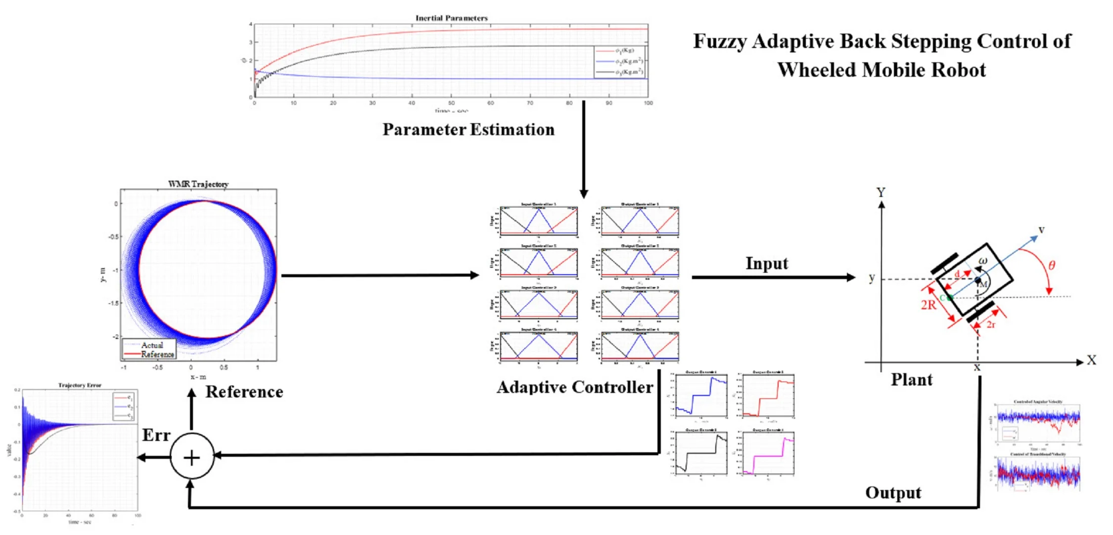
Wheeled mobile robots (WMR) are unmanned vehicles and practical robots for industry and human life. The low-cost manufacturing, simple assembling, high-speed, lightweight design, and high observability and controllability of the WMRs have attracted the attention of engineering disciplines such as mechanical and electrical science. This paper focuses on the control of wheeled mobile robots through fuzzy adaptive back stepping (ABS). The mathematical model of WMR is divided into two types, including kinematic and dynamic analyses. Actually, this research analyzes the theoretical math model using hybrid methods such as fuzzy logic and adaptive back stepping (BS) to control WMR in both noisy and noiseless conditions along its path. On the other hand, this hybrid controller, because of its more robust performance, can track WMR on its targets. Because of this, WMR's ability to move around makes it choose fuzzy and adaptive back stepping (FABS) methods, which use model-based and time-dependent features, respectively. As a result, the signal inputs fuzzy membership functions, and then the fuzzy approach outputs a new signal that goes to the back-step adaptive controller to finalize the control effort to navigate WMR with the lowest error during its destinations.
Highlights
- Hybrid Fuzzy Adaptive Backstepping (FABS) Architecture
- Comprehensive Kinematic and Dynamic Modeling
- Adaptive Observer and Controller in Noisy and Noiseless Conditions
- Fuzzy‐Based Gain Scheduling for Online Parameter Tuning
- Simulation Validation: Improved Tracking Accuracy and Stability
1. Introduction
The back stepping method, introduced in 1990, is a recursive design based on Lyapunov that offers a systematic approach to feedback control and Lyapunov functions. It is suitable for smooth matching conditions but has not addressed problems like stabilization control of uneven nonlinear systems, time-varying system parameters, and internal changes. This technique has been applied to various control system problems, including stability analysis methods and improvements in system tracking for transient performance. It involves designing stabilizing controllers from stabilized subsystems that may not be stabilized using other methods. Back stepping allows adjustment and utilization of additional nonlinear expressions within the control system, providing more flexibility than feedback linearization methods. Fuzzy systems play a significant role in control science, and this article aims to outline a systematic approach to adaptive fuzzy back stepping observers and employ state feedback in an adaptive fuzzy back stepping controller for managing a wheeled mobile robot in non-homogeneous states. A paper [1] introduces a symbolic algorithm for deriving motion equations of N-rigid link manipulators with revolute-prismatic joints on a mobile platform, utilizing recursive Gibbs-Appell formulation and dynamic interactions. Study [2] examines a multi-agent system of N wheeled mobile robots, focusing on collision avoidance through differential game formulation. Paper [3] presents a distributed proportional-integral data-driven iterative learning control (PI-DDILC) algorithm for non-holonomic wheeled mobile robots, enhancing response speed and performance. Study [4] explores motion control of tractor-trailer wheeled robots, designing a full-state trajectory tracking controller for stabilization. An adaptive integral terminal sliding mode (AITSM) control algorithm for Mecanum wheel robots is discussed in [5], showcasing superior tracking precision. Research [6] investigates optimal layouts for Differentially-Driven Wheeled Mobile Robots (DD-WMRs) in cooperative tasks, presenting analytical results. Study [7] proposes adaptive control approaches for two-wheeled robots using optimization methods, demonstrating effectiveness through simulations. An article [8] details a digital model for a three-wheeled omnidirectional robot, developed with Simscape for industrial applications. Paper [9] presents a stochastic dynamic model for wheeled robots, considering random perturbations. Study [10] examines a four-wheeled mobile platform dynamics model, analyzing motion parameters and slippage. Research [11] develops a skid steering model for accurate torque and power predictions in small robots. Study [12] presents a control law for trajectory tracking in non-holonomic robots, integrating evolutionary programming and adaptive fuzzy control. A publication [13] proposes fault detection schemes using adaptive threshold bands, validated through simulations. Research [14] introduces an adaptive trajectory tracking controller using neural networks for non-holonomic robots. Paper [15] proposes non-smooth kinematic control strategies for posture stabilization in differentially driven robots. Study [16] develops an adaptive controller for trajectory tracking in non-holonomic robots, validated through simulations. Research [17] details modeling of a differential drive robot for smooth trajectory tracking. Study [18] presents a PI-fuzzy path planner for omnidirectional robots, optimizing inputs for precise outputs. Research [19] introduces a discrete algorithm for tracking two-wheeled robots using Adaptive Critic Design. Study [20] presents a control rule for trajectory tracking in wheeled robots, enhancing autonomy through dynamic modeling. Paper [21] offers an adaptive fuzzy variable structure control for trajectory tracking in differential wheeled robots. Research [22] investigates coupled control of the “Agri-Eco-Robot” mobile agricultural robot, validating its effectiveness in rough environments. A novel transformable mobile robot for unstructured terrain is proposed in [23]. Analysis [24] presents a control strategy for coordinating multiple robots, validated through simulations. Assessment [25] compares locomotion performance of wheeled and tracked robots in agriculture, showing tracked robots outperforming wheeled ones. Evaluation [26] reiterates the digital model for a three-wheeled omnidirectional robot. Exploration [27] suggests a fuzzy logic controller for path tracking in wheeled robots, demonstrating effectiveness through implementation. Simulation [28] employs Dempster-Shafer and Kalman filter methods for mobile robot localization, confirming the superiority of the Kalman filter. Model [29] proposes adaptive robust control for under actuated robots, validated through simulations. Research article [30] introduces a hybrid controller design for autonomous path-following in non-holonomic robots. Review [31] discusses omnidirectional wheel mechanisms and navigation approaches in mobile robotics. Study [32] explores adaptive distributed formation control for non-holonomic robots. Survey [33] proposes an adaptive sliding-mode dynamic controller for achieving desired velocity in wheeled robots. Research [34] presents a reinforcement learning-based adaptive neural tracking algorithm for dynamic systems with skidding. Finally, reference [35] simulates a transformable wheel-leg mobile robot, analyzing movements and control systems. In this research, it will present a new method for designing and analyzing adaptive control systems based on the back stepping method within nonlinear dynamic systems. This research interest involves combining fuzzy back stepping adaptive observers with fuzzy adaptive back stepping controllers, a novel approach not previously reported.
2. Methodology
2.1. Kinematic model
The kinematic model of a WMR defines its motion based on velocity inputs and system constraints. Understanding the kinematics is essential for developing accurate trajectory tracking and motion control strategies. This section establishes the fundamental equations governing the motion of a WMR, providing a basis for designing effective control algorithms. By analyzing the kinematic equations, it is ensured that the control inputs result in smooth and precise navigation while maintaining stability. A wheeled mobile robot is considered with two actuator wheels.
Fig. 1WMR on Cartesian coordination
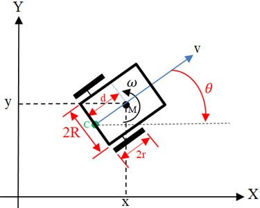
The geometric center of the robot is located at point C, while the midpoint is also between the two actuator wheels. The robot’s center of mass is at point M, and the distance from point C to M is denoted as . The coordinates of the center of mass M in the global coordinate system { are . The robot’s angle of rotation is positive for counterclockwise rotation. The distance from the geometric center to the center of the operator wheel is . The radius of the moving wheels is denoted by . It is assumed that the robot’s geometric center and center of mass do not coincide, although the likelihood of alignment is high. It is also assumed that the wheels rotate easily and do not slip. The non-holonomic structure can be expressed as follows:
Therefore, the kinematic description of the robot can be expressed as follows. The straight-line speed and the angular speed of the robot. It is presented Eq. (2) as a matrix in the following format:
Considering the transfer as follows:
where, and are reference coordination of and axes, respectively, in circle – shaped.
Therefore, the kinematic description of the robot model is shown in the following transformation:
Because Eq. (5) has a vertical transfer, there is no change in the unit’s values, and it is concluded that the tracking error of the original model converges to zero. Assume that the robot's reference kinematic model is given as follows:
And and are real coordination motion of robot in and axes, respectively. Where the ideal straight is linear speed and is the ideal angular speed of the robot. The tracking error of the system is given as follows:
The kinematic model provides a foundation for controlling WMRs by describing their motion in terms of linear and angular velocities. The transformation of reference coordinates enables precise trajectory tracking, minimizing errors in position and orientation. These equations serve as a crucial step in designing adaptive controllers that can handle uncertainties and external disturbances. The insights gained from this model contribute to the development of robust control strategies, which will be further enhanced through the integration of dynamic modeling and adaptive fuzzy logic.
2.2. Dynamic model
When the parameter is known, a common problem in tracking is the design of velocity and input controllers to make Eq. (8) asymptotically stable. However, in reality, it is very difficult to accurately identify the parameter. With the uncertainty of the parameter in this model, it will have an adaptive tracking controller. In engineering practice, formulation of non-holonomic control problems can be realized in dynamic levels, while force and torque are considered as control inputs, the dynamic description of the robot will be as follows [36]:
The matrices of the robot system in Eq. (9) are expressed as follows:
The general coordinate is represented by , while is a symmetric, definite positive inertial matrix. It serves as the Coriolis matrix, and the side-to-side indication shows the extent of surface wear. is the gravity vector, represents limited unknown disturbances, including unstructured dynamics, is the input transfer matrix and are the applied torque to the left and right wheels. represents the vector of constraint forces, while is the matrix associated with constraints. When considering the mobile robot under non-holonomic constraints, the matrix will look like this:
According to the Eq. (11):
By deriving from the sides of the equation and inserting it into the dynamic Eq. (9) and multiplying by its sides follow as:
Having:
The Eq. (9) will be transferred as follows:
The matrices of the dynamic are presented in Eq. (14), [37]:
where , that is the moment of inertia of the robot, is the mass of the robot, is the distance between the geometric center and the center of the wheels of the robot operator, and is the radius of the wheels of the operator. If is the virtual speed control of the system kinematics from Eq. (11), It is assumed that the tracking error rate is as follows:
By inserting Eq. (16) into Eq. (14) and using the linear property of the robot’s inertial parameters:
While:
The is the vector of the robot’s inertial parameters, such as the moment of inertia and mass, while represents a specific matrix that is unrelated to the robot’s inertial characteristics. In real motion, the surface friction vector and the irregularity vector are limited by a certain function. Therefore, , and are both bound (limited) by the same definite function [37]:
where is defined a specific value. The tracking problem for robot dynamics involves designing a control force or torqueto create a closed-loop system, asymptotically stable, using Eq. (8) and Eq. (17).
3. Adaptive control
The purpose of using adaptive control is that the controller designed in this way can respond appropriately to slow changes in the system as well as modeling errors. The difference between adaptive control and robust control is that in adaptive control, there is no need to know the system’s operating range or parameter error rate. In other words, the design from the perspective of resistant control results in a controller that stabilizes the system within a specific interval without requiring changes to the control rules. However, the adaptive control method allows for the adaptation of control rules to changing conditions, thereby achieving system stability.
3.1. Design of backward adaptive controller
To ensure the tracking error of Eq. (11) converges to zero, that assumes that the error estimation of is . Therefore, the virtual path tracking control law from the robot’s kinematic model is given as follows: Let’s assume that both and are bounded, with the lower limit being zero. It compensates for the following conditions:
Then, if it applies the speed control law according to Eq. (26) and the adaptive control law according to Eq. (24) to Eq. (8), the kinematic tracking error described by Eq. (11) will be asymptotically stable with Eq. (20):
That is, the tracking error tends to zero:
The adaptive control law is as follows:
While 0 and 0 and a is a positive constant [37].
3.2. Dynamic adaptive control
In Eq. (21), tracking control only kinematic speed is considered, although in reality, it is very difficult to have an ideal speed control. It should also be stated that the error between the operator speed and the ideal speed control will not be zero, which means that Eq. (23) is the only ideal kinematic speed control. To achieve torque control, the tracking error speed in Eq. (14) must converge to zero. Also, in this article, the value of is unknown and is an estimate of the therefore . This article assumes an unknown value for the tracking error, which serves as an estimate of its own error. Robot is assumed that , and , that are bounded, and then using the speed control law in Eq. (26) and the dynamic adaptive control law in Eq. (27) and Eq. (28) are mentioned [2]:
Tracking error position , :
The adaptive control law is as follows [2]:
While 0 and 0, is a positive matrix and all design parameters [36].
3.3. Fuzzy set
A fuzzy logic system consists of the following 4 general parts:
– Fuzzy rule base.
– Fuzzifier.
– Non-phase generator.
– Inference engine.
The fuzzy rule base for the fuzzy system consists of a set of if-then rules as follows:
and that are fuzzy membership functions, is called the degree of membership of in . Basic fuzzy functions are defined as follows [38], [36]:
A fuzzy logic system can be written as follows:
4. Result and discussion
Fig. 2 presents a block diagram of a kinematic adaptive back stepping observer. It provides a schematic description of mobile robot simulation using the block diagram of the mobile robot model and the equations established in the previous chapter. As illustrated in Fig. 2, to facilitate system tracking with the observer and kinematic controller, the following block diagram can be comprehensively understood.
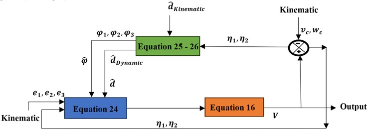
The block diagram (see Fig. 3) of dynamic adaptive feedback controller. In the mobile robot design, which leads to the design of the backward adaptive control law, is shown in the form of a block diagram (see Fig. 3).
This section addresses the evaluation of adaptive back stepping control as an observer and the design of adaptive fuzzy back stepping control. Initially, the observer is developed under ideal conditions without noise or external disturbances to assess the robot’s performance in an ideal state. Subsequently, the adaptive back stepping observer is designed to operate in the presence of external noise factors, specifying the type of input noise through diagrams. Finally, the impact of fuzzy design and its application on the robot model is fully illustrated using diagrams, culminating in the design of the adaptive fuzzy controller. Parameters are optimized using scientific methods and fuzzy logic before integration into the system.
Fig. 2Adaptive controller based on kinematic model of the WMR
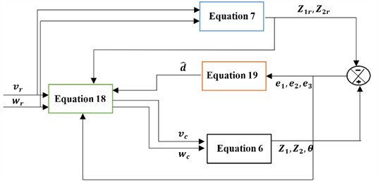
Fig. 3Adaptive controller based on dynamic model of the WMR
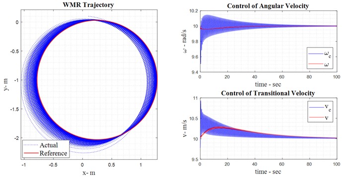
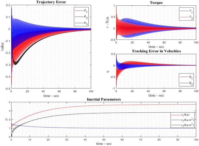
4.1. Robot observation without noise
The reference model of the robot is shown as a red circle, and the tracker model can also be seen as blue. In order to evaluate the tracker models, these two graphs can be seen next to each other in the third graph. As illustrated in Fig. 4, the kinematic back stepping adaptive control law operates in the absence of noise, as previously discussed in the chapter. The control input or effort in the adaptive observer mode, as per Eq. (8), reflects the errors of the robot under noise-free conditions. In the feedback controller, the control torque representing the control effort without noise is described by Eq. (26). The tracking error, defined as the difference between the control speed and the mobile robot’s speed, is formulated in Eq. (16). Based on Eq. (27), which defines the dynamic adaptive control law for the mobile robot, this control law vector evolves and is depicted in Fig. 4.
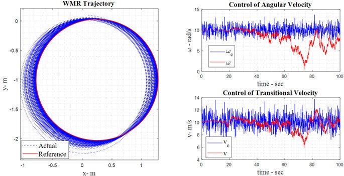
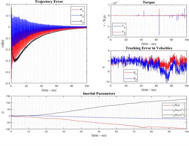
4.2. Robot observation with noise
In the presence of noise in the mobile robot system model, the relevant diagrams are depicted as follows: Based on Eq. (20), which incorporates external friction and friction force, as shown below, over the simulated time period of the mobile robot. Fig. 5 illustrates the presence of noise in the backward adaptive observer mode, depicting the reference and real models. The accuracy of the adaptive observer can be fully understood in Fig. 5 illustrates the adaptive observer control law for estimating kinematic behavior in the presence of noise. It details the adaptation of linear and angular velocities using the kinematic back stepping approach under noisy conditions, emphasizing the system’s state error due to external noise. The control torque, determined by the adaptive dynamic back stepping control approach, is designed for the first and second system inputs. Additionally, the system’s tracking speed is derived from Eq. (16) and Eq. (27).
Fig. 4Result of robot observation without noise
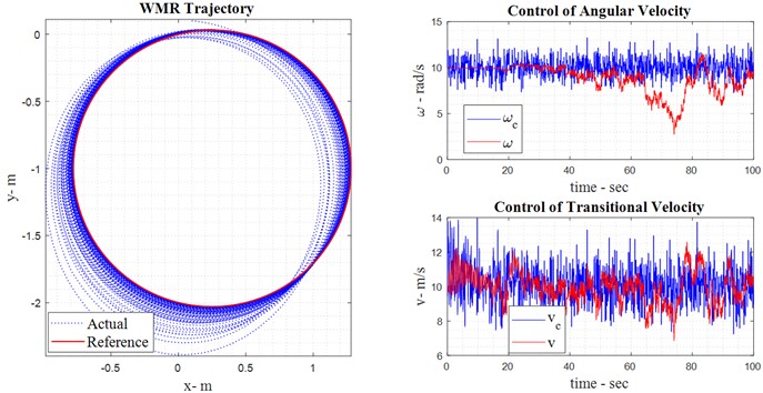
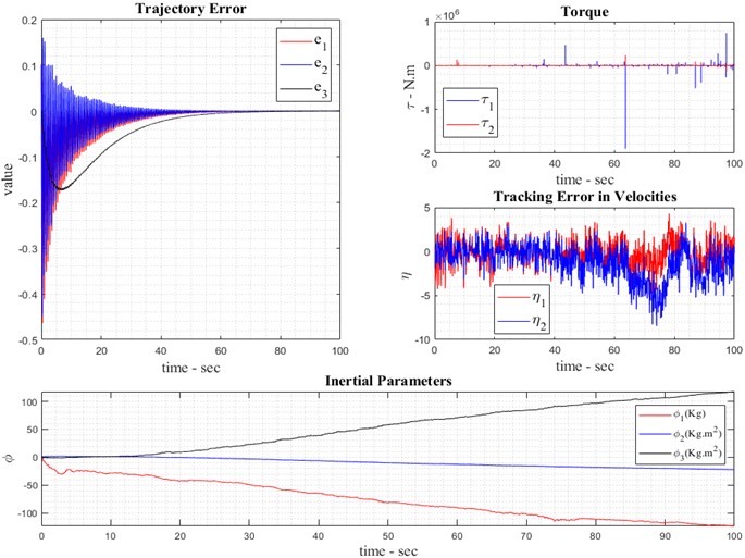
4.3. Fuzzy control with noise
This section introduces the incorporation of fuzzy logic into the backward comparative perspective. The purpose of applying the fuzzy approach is to introduce fuzzy parameters, known as control gains, into the system. These parameters, , , and in Eq. (24) and Eq. (28), are fuzzified to enhance system control. Designing fuzzy parameters involves fundamental concepts detailed in the section on fuzzified parameter. Fig. 6 illustrates the real model and fuzzy reference of the robot. Essentially, the integration of fuzzy logic with the adaptive feedback controller aims to automate the tuning of control gains instead of relying on manual or trial-and-error methods. As described by Eq. (26), fuzzy logic adjusts these control functions within a range defined by membership functions, thereby optimizing the system's ability to track its path. Based on the fuzzy design for adaptive back stepping control of the system, the kinematic back stepping adaptive control parameters, considering both noise and fuzzification, are described as follows: angular velocity and linear velocity (see Eq. (23)). The adaptive control error for kinematic fuzzy back stepping in the presence of noise is given by Eq. (26), which expresses the control torque as the control effort designed using backward adaptive fuzzy control and applied to the system input. The tracking speed in both linear and angular modes in the presence of noise is demonstrated through the design of the backward adaptive fuzzy controller. Fig. 6 illustrates the parameters defined in Eq. (27), representing the adaptive control law utilizing the fuzzy approach in the presence of noise.
Fig. 5Result of robot observation with noise
5. Fuzzy parameters
In the design of control parameters through fuzzy logic, it is essential to incorporate several key elements, including:
5.1. The first element
Based on Table 1, the inputs and outputs of the mobile robot should be determined, distinguishing between fuzzified inputs and non-fuzzified outputs for the system (see Fig. 7).
Fig. 6Result of fuzzy robot control with noise
5.2. The second element
Selection of rules for input and output membership functions (see Fig. 7).
Table 1Determined input and output variables
Input | Output |
Table 2Control rule-based of the fuzzy
Input | Output | ||
Low | Normal | High | |
Low | Low | Low | Normal |
Normal | Low | Normal | High |
High | Normal | High | High |
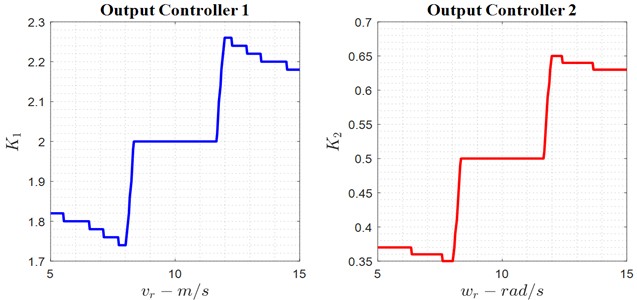
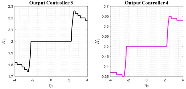
Fig. 7Adaptive values of the K1, K2, and K3
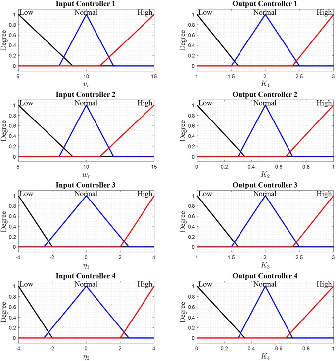
5.3. The third element
Selecting the type of membership functions for input and output (triangular, Gaussian, trapezoidal, etc.). To perform the fuzzification of the parameters for the backward adaptive controller, the graphs related to these three elements can be fully reviewed and analyzed. Initially, the dependence of the inputs and outputs of the system and the controller is illustrated in Fig. 8. The selected membership functions are triangular, indicating the degree of connection between the inputs and outputs. Finally, this provides information on the magnitude of the control parameters fed to the system in each time frame to enable proper system control.
6. Conclusions
This research successfully demonstrates the effectiveness of a fuzzy adaptive back stepping (ABS) controller in enhancing the trajectory tracking and robustness of wheeled mobile robots (WMRs). By integrating fuzzy logic with back stepping control, the proposed approach significantly improves path-following accuracy under both noisy and noiseless conditions. The combination of kinematic and dynamic modeling ensures precise motion control, while adaptive tuning mechanisms allow the system to respond effectively to external disturbances and uncertainties. Simulation results validate the superiority of the proposed controller, showing reduced tracking errors, minimized chattering, and improved stability compared to conventional methods.
Fig. 8Membership functions of fuzzy robot control
The ability of the system to maintain performance in noisy environments highlights its practical applicability in real-world robotic navigation and industrial automation. For future researchers, this article strongly recommends further development in various engineering concepts. For example, using PZT sensors on WMRs can control vibrations in the , , and directions. There are different active and passive methods and strategies to achieve this [39-42]. Furthermore, in control engineering, specifically, hybrid controllers combined with optimization algorithms can effectively enhance the capabilities of WMRs on both large and small scales. Examples include PWM, LQR-PID, sliding mode-PID, Fuzzy-PID, PID-PSO, LQR-MOPSO, and H∞ control [43-47]. Finally, from an experimental perspective, it is suggested to augment WMRs with a DC-DC converter [48].
References
-
E. Maalouf, M. Saad, and H. Saliah, “A higher level path tracking controller for a four-wheel differentially steered mobile robot,” Robotics and Autonomous Systems, Vol. 54, No. 1, pp. 23–33, Jan. 2006, https://doi.org/10.1016/j.robot.2005.10.001
-
R. M. Bhatt, C. P. Tang, and V. N. Krovi, “Formation optimization for a fleet of wheeled mobile robots – A geometric approach,” Robotics and Autonomous Systems, Vol. 57, No. 1, pp. 102–120, Jan. 2009, https://doi.org/10.1016/j.robot.2006.12.012
-
C.-Y. Chen, T.-H. S. Li, and Y.-C. Yeh, “EP-based kinematic control and adaptive fuzzy sliding-mode dynamic control for wheeled mobile robots,” Information Sciences, Vol. 179, No. 1-2, pp. 180–195, Jan. 2009, https://doi.org/10.1016/j.ins.2008.09.012
-
C.-Y. Chen, T.-H. S. Li, Y.-C. Yeh, and C.-C. Chang, “Design and implementation of an adaptive sliding-mode dynamic controller for wheeled mobile robots,” Mechatronics, Vol. 19, No. 2, pp. 156–166, Mar. 2009, https://doi.org/10.1016/j.mechatronics.2008.09.004
-
J. Ghommam, M. Saad, and F. Mnif, “Formation path following control of unicycle-type mobile robots,” 2008 IEEE International Conference on Robotics and Automation. The Half-Day Workshop on: Towards Autonomous Agriculture of Tomorrow, Vol. 58, No. 5, pp. 1966–1972, May 2008, https://doi.org/10.1109/robot.2008.4543495
-
E. Hashemi, M. Ghaffari Jadidi, and N. Ghaffari Jadidi, “Model-based PI-fuzzy control of four-wheeled omni-directional mobile robots,” Robotics and Autonomous Systems, Vol. 59, No. 11, pp. 930–942, Nov. 2011, https://doi.org/10.1016/j.robot.2011.07.002
-
Z. Hendzel and M. Szuster, “Discrete neural dynamic programming in wheeled mobile robot control,” Communications in Nonlinear Science and Numerical Simulation, Vol. 16, No. 5, pp. 2355–2362, May 2011, https://doi.org/10.1016/j.cnsns.2010.04.046
-
O. Mohareri, R. Dhaouadi, and A. B. Rad, “Indirect adaptive tracking control of a nonholonomic mobile robot via neural networks,” Neurocomputing, Vol. 88, pp. 54–66, Jul. 2012, https://doi.org/10.1016/j.neucom.2011.06.035
-
M. H. Korayem and A. M. Shafei, “Motion equation of nonholonomic wheeled mobile robotic manipulator with revolute-prismatic joints using recursive Gibbs-Appell formulation,” Applied Mathematical Modelling, Vol. 39, No. 5-6, pp. 1701–1716, Mar. 2015, https://doi.org/10.1016/j.apm.2014.09.030
-
F. Baghernezhad and K. Khorasani, “Computationally intelligent strategies for robust fault detection, isolation, and identification of mobile robots,” Neurocomputing, Vol. 171, pp. 335–346, Jan. 2016, https://doi.org/10.1016/j.neucom.2015.06.050
-
D. Huang, J. Zhai, W. Ai, and S. Fei, “Disturbance observer-based robust control for trajectory tracking of wheeled mobile robots,” Neurocomputing, Vol. 198, pp. 74–79, Jul. 2016, https://doi.org/10.1016/j.neucom.2015.11.099
-
N. Leena and K. K. Saju, “Modelling and trajectory tracking of wheeled mobile robots,” Procedia Technology, Vol. 24, pp. 538–545, Jan. 2016, https://doi.org/10.1016/j.protcy.2016.05.094
-
Z. Peng, S. Yang, G. Wen, A. Rahmani, and Y. Yu, “Adaptive distributed formation control for multiple nonholonomic wheeled mobile robots,” Neurocomputing, Vol. 173, pp. 1485–1494, Jan. 2016, https://doi.org/10.1016/j.neucom.2015.09.022
-
M. Begnini, D. W. Bertol, and N. A. Martins, “A robust adaptive fuzzy variable structure tracking control for the wheeled mobile robot: Simulation and experimental results,” Control Engineering Practice, Vol. 64, pp. 27–43, Jul. 2017, https://doi.org/10.1016/j.conengprac.2017.04.006
-
A. Jaskot, B. Posiadała, and S. Śpiewak, “Dynamics modelling of the four-wheeled mobile platform,” Mechanics Research Communications, Vol. 83, pp. 58–64, Jul. 2017, https://doi.org/10.1016/j.mechrescom.2017.05.007
-
S. Li, L. Ding, H. Gao, C. Chen, Z. Liu, and Z. Deng, “Adaptive neural network tracking control-based reinforcement learning for wheeled mobile robots with skidding and slipping,” Neurocomputing, Vol. 283, pp. 20–30, Mar. 2018, https://doi.org/10.1016/j.neucom.2017.12.051
-
T. Mylvaganam and M. Sassano, “Autonomous collision avoidance for wheeled mobile robots using a differential game approach,” European Journal of Control, Vol. 40, pp. 53–61, Mar. 2018, https://doi.org/10.1016/j.ejcon.2017.11.005
-
P. Panahandeh, K. Alipour, B. Tarvirdizadeh, and A. Hadi, “A kinematic Lyapunov-based controller to posture stabilization of wheeled mobile robots,” Mechanical Systems and Signal Processing, Vol. 134, p. 106319, Dec. 2019, https://doi.org/10.1016/j.ymssp.2019.106319
-
X. Chen, H. Zhao, H. Sun, S. Zhen, and K. Huang, “A novel adaptive robust control approach for underactuated mobile robot,” Journal of the Franklin Institute, Vol. 356, No. 5, pp. 2474–2490, Mar. 2019, https://doi.org/10.1016/j.jfranklin.2019.01.002
-
H. Jiang, G. Xu, W. Zeng, and F. Gao, “Design and kinematic modeling of a passively-actively transformable mobile robot,” Mechanism and Machine Theory, Vol. 142, p. 103591, Dec. 2019, https://doi.org/10.1016/j.mechmachtheory.2019.103591
-
S. Erfani, A. Jafari, and A. Hajiahmad, “Comparison of two data fusion methods for localization of wheeled mobile robot in farm conditions,” Artificial Intelligence in Agriculture, Vol. 1, pp. 48–55, Mar. 2019, https://doi.org/10.1016/j.aiia.2019.05.002
-
T. Guo, J. Guo, B. Huang, and H. Peng, “Power consumption of tracked and wheeled small mobile robots on deformable terrains-model and experimental validation,” Mechanism and Machine Theory, Vol. 133, pp. 347–364, Mar. 2019, https://doi.org/10.1016/j.mechmachtheory.2018.12.001
-
K. Alipour, A. B. Robat, and B. Tarvirdizadeh, “Dynamics modeling and sliding mode control of tractor-trailer wheeled mobile robots subject to wheels slip,” Mechanism and Machine Theory, Vol. 138, pp. 16–37, Aug. 2019, https://doi.org/10.1016/j.mechmachtheory.2019.03.038
-
P. Kassaeiyan, K. Alipour, and B. Tarvirdizadeh, “A full-state trajectory tracking controller for tractor-trailer wheeled mobile robots,” Mechanism and Machine Theory, Vol. 150, p. 103872, Aug. 2020, https://doi.org/10.1016/j.mechmachtheory.2020.103872
-
H. Taheri and C. X. Zhao, “Omnidirectional mobile robots, mechanisms and navigation approaches,” Mechanism and Machine Theory, Vol. 153, p. 103958, Nov. 2020, https://doi.org/10.1016/j.mechmachtheory.2020.103958
-
I. Mertyüz, A. K. Tanyıldızı, B. Taşar, A. B. Tatar, and O. Yakut, “FUHAR: A transformable wheel-legged hybrid mobile robot,” Robotics and Autonomous Systems, Vol. 133, p. 103627, Nov. 2020, https://doi.org/10.1016/j.robot.2020.103627
-
Z. Sun, S. Hu, D. He, W. Zhu, H. Xie, and J. Zheng, “Trajectory-tracking control of Mecanum-wheeled omnidirectional mobile robots using adaptive integral terminal sliding mode,” Computers and Electrical Engineering, Vol. 96, p. 107500, Dec. 2021, https://doi.org/10.1016/j.compeleceng.2021.107500
-
R. Hou, L. Cui, X. Bu, and J. Yang, “Distributed formation control for multiple non-holonomic wheeled mobile robots with velocity constraint by using improved data-driven iterative learning,” Applied Mathematics and Computation, Vol. 395, p. 125829, Apr. 2021, https://doi.org/10.1016/j.amc.2020.125829
-
M. B. Emara, A. W. Youssef, M. Mashaly, J. Kiefer, L. A. Shihata, and E. Azab, “Digital twinning for closed-loop control of a three-wheeled omnidirectional mobile robot,” Procedia CIRP, Vol. 107, pp. 1245–1250, Jan. 2022, https://doi.org/10.1016/j.procir.2022.05.139
-
S. Mondal, R. Ray, S. R. N., and S. Nandy, “Intelligent controller for nonholonomic wheeled mobile robot: A fuzzy path following combination,” Mathematics and Computers in Simulation, Vol. 193, pp. 533–555, Mar. 2022, https://doi.org/10.1016/j.matcom.2021.10.028
-
D. Liu, M. Tang, and J. Fu, “Robust adaptive trajectory tracking for wheeled mobile robots based on Gaussian process regression,” Systems and Control Letters, Vol. 163, p. 105210, May 2022, https://doi.org/10.1016/j.sysconle.2022.105210
-
Y. Olmez, G. O. Koca, and Z. H. Akpolat, “Clonal selection algorithm based control for two-wheeled self-balancing mobile robot,” Simulation Modelling Practice and Theory, Vol. 118, p. 102552, Jul. 2022, https://doi.org/10.1016/j.simpat.2022.102552
-
F. Vesentini, L. Di Persio, and R. Muradore, “A Brownian-Markov stochastic model for cart-like wheeled mobile robots,” European Journal of Control, Vol. 70, p. 100771, Mar. 2023, https://doi.org/10.1016/j.ejcon.2022.100771
-
R. Majdoubi, L. Masmoudi, and A. Elharif, “Coupled nonlinear controller for vehicle trajectory tracking in a deformable soil: Application to a four-wheeled mobile agricultural robot,” Journal of Terramechanics, Vol. 110, pp. 47–68, Dec. 2023, https://doi.org/10.1016/j.jterra.2023.08.001
-
S. M. Shafaei and H. Mousazadeh, “Experimental comparison of locomotion system performance of ground mobile robots in agricultural drawbar works,” Smart Agricultural Technology, Vol. 3, p. 100131, Feb. 2023, https://doi.org/10.1016/j.atech.2022.100131
-
R. Fierro and F. L. Lewis, “Control of a nonholomic mobile robot: Backstepping kinematics into dynamics,” Journal of Robotic Systems, Vol. 14, No. 3, pp. 149–163, Mar. 1997, https://doi.org/10.1002/(sici)1097-4563(199703)14:3<149::aid-rob1>3.3.co;2-n
-
N. Hu and C. Wang, “Adaptive tracking control of an uncertain nonholonomic robot,” Intelligent Control and Automation, Vol. 2, No. 4, pp. 396–404, Jan. 2011, https://doi.org/10.4236/ica.2011.24045
-
L.-X. Wang, A course in fuzzy systems. Prentice Hall PTR, 1999.
-
M. Hasanlu, A. Bagheri, and F. Najafi, “Optimal placement of piezoelectric S/A for active vibration control of engineering structures by using controller design,” Research and Reviews: Journal of Engineering and Technology, Vol. 5, No. 4, pp. 22–44, 2016.
-
M. Hasanlu and A. Bagheri, “Optimal Locations on Timoshenko Beam with PZT S/A for Suppressing 2Dof Vibration Based on LQR-MOPSO,” Journal of Solid Mechanics, Vol. 10, No. 2, pp. 364–386, 2018.
-
M. Hasanlu, M. Siavashi, and A. Bagheri, “Vibration attenuation Timoshenko beam based on optimal placement sensors/actuators PZT patches with LQR-MOPSO,” Iranian Journal of Mechanical Engineering, Vol. 17, No. 1, pp. 26–60, 2016.
-
M. Hasanlu, M. Siavashi, and A. Bagheri, “Free vibration analysis of metamaterial functionally graded plates with quasi-zero stiffness resonators,” Noise and Vibration Worldwide, Vol. 54, No. 2-3, pp. 108–121, Jan. 2023, https://doi.org/10.1177/09574565231154248
-
M. Siavashi and M. Hasanlu, “Experimental optimal control of servo-pneumatic with sliding mode and GA-fuzzy-PID-PWM,” Journal of Mechatronics and Artificial Intelligence in Engineering, Vol. 5, No. 2, pp. 199–214, Dec. 2024, https://doi.org/10.21595/jmai.2024.24656
-
M. Hasanlu, M. Siavashi, M. Soltanshah, and A. Bagheri, “Fuzzy-PID controller design for random vibration attenuated smart cantilever Timoshenko beam based on MOGA algorithm,” 3rd International Conference on Researches in Science and Engineering, 2017.
-
M. Hasanlu and A. Bagheri, “Intelligent control smart Timoshenko beam by using MOPSO-PID controller based on optimal location PZT patch actuator approach,” Iranian Journal of Mechanical Engineering, Vol. 20, No. 3, pp. 6–28, 2018.
-
M. Karami Gavgani, M. Hasanlu, and M. Nikkho, “Optimal position control of nonlinear muscle based on sliding mode and particle swarm optimization algorithm,” Transactions on Machine Intelligence, Vol. 5, No. 1, pp. 37–45, Dec. 2022, https://doi.org/10.47176/tmi.2022.37
-
M. Hasanlu and M. Siavashi, “Nonlinear control of quadrotor trajectory with discrete H∞,” Journal of Mechanical Engineering, Automation and Control Systems, Vol. 6, No. 1, pp. 1–13, Jan. 2025, https://doi.org/10.21595/jmeacs.2024.24602
-
F. Salari and M. Hasanlu, “Optimal model predictive fuzzy control of DC-DC convertor,” Advanced Control for Applications, Vol. 6, No. 1, p. e169, Dec. 2023, https://doi.org/10.1002/adc2.169
Cited by
About this article

The authors have not disclosed any funding.
The datasets generated during and/or analyzed during the current study are available from the corresponding author on reasonable request.
The authors declare that they have no conflict of interest.
