Abstract
Delta robots play a critical role in high-speed industrial applications due to their parallel kinematic structure, which provides superior precision, agility, and efficiency. This study presents a reconfigurable Delta robot with a novel structural adaptation mechanism, allowing geometric modifications to optimize its kinematic and dynamic performance. The research systematically derives the robot’s kinematic and dynamic equations, examines the impact of altering the structure of its chains, and applies genetic algorithm optimization to enhance its overall functionality. The influence of varying arm lengths, chain structures, and joint configurations is analyzed to determine their effects on workspace, actuator torque requirements, and operational stability. The findings indicate that optimized chain configurations improve workspace utilization by up to 15 %, reduce actuator torque by 12 %, and enhance end-effector speed by 8 %. By integrating structural adaptability and optimization techniques, this study demonstrates that the reconfigurable Delta robot achieves a superior balance between precision, speed, and energy efficiency. These advancements make it a promising solution for next-generation high-speed robotic applications in industries such as packaging, assembly, and medical automation.

Highlights
- Reconfigurable Delta Robot – A novel adaptive structure enhances kinematic and dynamic performance.
- Genetic Algorithm Optimization – Achieves 15% more workspace, 12% torque reduction, and 8% speed improvement.
- Kinematic & Dynamic Analysis – Examines arm lengths, chain structures, and joint configurations.
- Industrial Applications – Optimized for high-speed tasks in packaging, assembly, and medical automation.
- Future Research – Focus on AI-driven control, advanced materials, and real-time adaptability.
1. Introduction
This robot is increasingly used for moving light and small objects at high speeds, utilizing a position sensor to measure the device’s location and apply control commands in case of disturbances, with a camera installed to track specific objects, among other applications. One notable feature of this robot is the presence of fixed motors. The main distinction between delta robots and serial robots lies in the fixed motors and lighter arms of the delta type, which not only reduce the weight of the arms but also enhance the speed and accuracy of movements. Another unique feature of this robot is the level of common support or parallel arms. Compliance with this principle has made this generation the best option for tasks such as picking and placing objects and moving loads. Similar structures can be used for functional parallel robots. One method to address this issue is to modify the structure of parallel robots, resulting in a design that is both suitable and efficient under various functional conditions. Modifications to the Delta robot’s structure can include adjustments to the joints, arm length, chain type, arm positioning, and any other changes desired by the robot designer. In 1984, Raymond Clavel, working as a marketer for a newly established chocolate company, came up with the idea to automate the chocolate packing process using a powerful mechanism, rather than relying on human labor. He shared the idea with his research team at his university, and they agreed that they could develop a robot to perform this monotonous, repetitive task quickly. In less than a year, Clavel and his team designed and built a prototype. Although valuable, this initial version was still weak in terms of performance. After a week of analysis and design simplification, Clavel created a model closer to an optimal design, which was recognized as the Delta robot. In 1991, Clavel presented his PhD thesis titled “Design of a Fast Parallel 4-DoF Robot”, and in 1999, he was awarded the Golden Robot Award for his work on the Delta robot [1]. In 1987, the Swiss company DEMAUREX SA acquired a license for the Delta robot and began manufacturing it for the packaging industry. That same year, ABB began selling its Delta robot under the Flex Picker brand. Later, a Swiss company acquired De Marks to produce only surgical products, creating a Delta robot designed to carry a 2-kg microscope during surgeries. Adept also developed its parallel Delta robot, known as the Quattro, for the packaging industry. Fig. 1 shows a view of this robot. Other companies, including Kawasaki Robotics from the United States and Fanuc from Japan, also developed 4-degree-of-freedom and 6-degree-of-freedom Delta robots. Industries that benefited from the high speed of this robot include the packaging, medical, and pharmaceutical sectors. It is also used in surgeries and assembly due to its high strength [1]. After the Delta robot's success as a super-fast parallel robot in industry, interest in studying and developing it increased in universities and academic environments. Numerous universities began designing and implementing the Delta robot for educational and research purposes. Tsai built an academic robot at the University of Maryland [2], and a modified version of the robot was developed at the University of Genoa. This design replaced the robot's parallelogram with a different mechanism. Another simplified version of the robot, capable of achieving acceleration values six times that of gravity, was built at the University of Western Australia. Another version, using linear motors instead of rotary motors, was developed at the Swiss ETH and Stuttgart universities. At Tohoku University, a Delta robot was used as part of the interface for a 6-degree-of-freedom touch robot. Later, several Delta educational robots were built at EPFL University, considered the birthplace of this robot, under the supervision of Professor Clavel and his research team [1]. To understand the unique advantages of the Delta robot, it is necessary to compare it with conventional serial robots. A conventional robot functions like a human mechanism, rotating at the joints for pick-and-place operations. Despite their widespread use in many industries, these robots have limitations. They are most suitable for environments where the parts they handle weigh more than 5 pounds. In some tasks, robot mobility is more important than the precision of component placement. However, Delta robot technology is specifically designed for handling light objects with exceptional accuracy and speed. This design emerged when most industrial robots were of the serial type, characterized by chains and multiple arms mimicking human movements. The name “Delta Robot” is derived from a concept based on the deltoid muscles in humans. Each arm of the Delta robot functions similarly to a shoulder muscle, giving it greater movement capabilities than conventional robots [3]. Before the Delta robot, conventional robots were equipped with arms weighing more than 40 pounds, requiring motors to be attached to the arms. These robots typically had 4-8 rotational or linear axes to achieve desired movements. The mechanism's ability to support such heavy arms significantly slowed production speed. Moreover, these robots were limited to movements involving back-and-forth rotational motions. Due to the popularity of the Delta robot’s parallel and fast structure, many studies and research projects have been conducted on it in the areas of design, kinematics, dynamics, and control. The robot’s main designer, conducted the first scientific research on the Delta robot in 1991 as part of his doctoral dissertation [4]. In his dissertation, he explained the structure of the Delta robot, its workspace volume, analyzed its dynamics using the virtual work method, and compared its performance with that of the SCARA series robot. In [5], he analyzed the robot’s kinematic model and examined its working space in terms of volume and warping. In [6], the robot’s kinematic model was derived from a geometric analysis of its joints and interfaces. In the inverse kinematics model was introduced, followed by an analysis of the robot’s performance using various kinematic indicators within its workspace. A new design of the Delta robot’s 4-arm structure and dynamic brass bodies was presented in [7, 8], where rotational degrees of freedom were achieved without adding additional actuators. In [9], a new design based on the robot’s dynamic model was presented and evaluated using an ANSYS model. In [10], the robot’s kinematic parameters were optimized using the Monte Carlo method to maximize the working space and improve the robot’s skill index. The Culling optimization algorithm [11] presented another method of optimizing the robot’s structure based on kinematic and dynamic indicators, including the robot’s Jacobian matrices and mass matrix. A constrained nonlinear optimization using gradient descent and random search was employed in [12] to obtain the robot’s kinematic parameters. The skill index and the robot's effective workspace were used for this purpose. The generalized pattern search algorithm was described in [13]. In [14], single-objective optimization was achieved using the genetic algorithm method, considering the inverse kinematic index of the robot’s state number. In dynamics and control, [15] employed the Lagrange method to determine the robot’s dynamics, accounting for the inertia of the parallelogram arms and utilizing PD control with a nonlinear feedforward term. [16, 17] calculated the robot’s dynamics using the virtual work method and torque control. The [18] applied this method to a Delta robot using linear actuators instead of sliders. In [19], the authors introduced a dynamic model aimed at overcoming gravity’s dynamic effect, using a PID control method for cost-effective robot control. In [20], a robust control method was proposed, involving an analysis of the robot’s nonlinear state space equations to address model uncertainties. This led to a three-part control method for positioning system modes. In time path design, [21] introduced a sinusoidal time curve for vector and transition tasks, aimed at minimizing time. Staiko et al. [22] conducted dynamic and kinematic analysis of the Delta robot, examining its speed and degrees of freedom, ultimately presenting the robot’s chain matrix and motion graph. Stan et al. [23] improved the robot’s movement performance with a new model. J. Zhang et al. [24], through the analysis of the Delta robot’s workspace and routing dynamics using a type of belt, enhanced speed, accuracy, and workspace utility. John Brinker [25] introduced a random path selection algorithm, ensuring the robot’s accuracy and high speed. Liu et al. and Gagliardini et al. [26, 27] used machine learning to investigate the Delta robot's safety and direct kinematics, contributing to its application in large-area painting. Jin et al. [28] presented a deformable robot structure called Qrpara, enhancing motion capabilities with five flexible axes. Wu et al. [29] improved robot performance by introducing a hexa robot’s deformable structure. Li et al. [30] achieved the highest dynamic level by redesigning the deformable structure of the Steve Wart robot. Alison et al. [31] are exploring the creation of adaptable structures capable of performing various tasks. By analyzing power coefficients and angles, Brinker et al. [32] succeeded in enhancing the robot's performance indicators and reducing movement limitations. Among the innovations of this research that distinguish it from previous studies is the development of a malleable structure for the Delta parallel robot. This structure can adapt its shape to meet specific needs, effectively performing assigned tasks. The hypotheses of this research assume that the robot members are rigid, some have the ability to change shape, the robot’s dynamics are fully considered, and the joints are designed with no slack. Therefore, one of the innovations of this research is the introduction of a new deformable structure for the Delta parallel robot, along with a method for modifying it to achieve the desired performance. Recent advancements in Delta robot design have focused on improving workspace utilization, motion stability, and control precision. Conventional Delta robots utilize fixed geometric configurations, which limit their adaptability to varying operational requirements. Several studies [4-9] have explored kinematic and dynamic optimization, with approaches such as Monte Carlo simulation, constrained nonlinear optimization, and dexterity-based workspace enhancement. While these methods offer performance improvements, they do not address real-time structural adaptability, restricting their effectiveness in dynamic industrial environments. In contrast, this study introduces a reconfigurable Delta robot that enables structural modifications to optimize workspace, torque efficiency, and dynamic responsiveness. By incorporating a genetic algorithm-based optimization framework, we enhance performance metrics beyond existing fixed-geometry designs. Our findings demonstrate a 15 % increase in workspace, a 12 % reduction in actuator torque, and an 8 % improvement in speed, surpassing the capabilities of traditional optimization techniques. This approach provides a more flexible and efficient robotic system for high-speed industrial applications, such as automated assembly, precision packaging, and surgical robotics.
2. Methodology
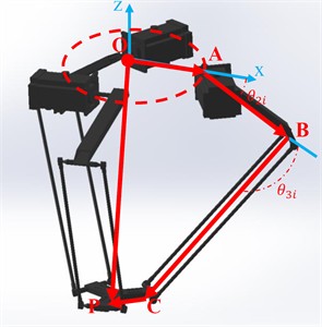
In this section, that develops a new model based on a geometric constraint within the structure of the Delta robot. After deriving the constraint equation using the loop method is proceed to formulate both the inverse and direct kinematics. It will be considered the vector that connects the origin of the robot’s fixed plane to the center of the final operator. Subsequently, applying the known vector relationships within the robot’s kinematic chains to derive a corresponding relationship for the position vector of interest. The joint coordinates and link lengths will facilitate this process. As illustrated in the Fig. 1, the coordinates of points , , and can be determined relative to the : - frame (Fig. 1(b)):
where in:
Fig. 1Schematic half-side of Delta robot, a) 3D model, b) vectorizing end effector
a)
b)
The coordinates of the final robot operator's origin are then determined:
Since the chains are positioned at a 120-degree angle and are symmetrical to each other, the obtained coordinates, written relative to the frame, should be transformed for each chain using the rotation matrix , , therefore:
where in:
Then:
To eliminate the inactive elements are squared the relationship and then sum the results:
2.1. Direct kinematic
The input to the problem is the position of the end effector in direct kinematics (DK), and the output is the position of the moving platform. Direct kinematics is commonly used in robotics for simulation and laboratory tasks. A schematic diagram of the direct kinematics solution is provided in the Fig. 2 designed the delta robot, it is essential to understand specific values and dimensions, which, when combined with the fewest number of parameters, can fully define the robot’s structure and workspace. In delta robots, there are typically four design parameters. The Fig. 1 clearly illustrates these four design parameters in Table 1.
Table 1Influential parameters on designing delta robot
Parameter | Description |
Radius of base circular | |
Radius of circular motion | |
Length link 1 | |
Length link 2 |
Given our goal of minimizing the number of parameters in the design, the Fig. 1 demonstrates that the radii of the base and moving circles are aligned in the same direction, indicating that the moving circle does not rotate relative to the base circle. Therefore, to simplify the parameters are considered the difference between the values of these two radii in our calculations. In reality, when solving for the inverse kinematics and the working space, only the difference between these two parameters is relevant. As a result, that will have three key design parameters, as shown in the Fig. 2 establishes a vector relationship for the robot's parallelogram link, the Eq. (8) represents this relationship, which effectively describes the length of the parallelogram arm in the Fig. 2:
To substitute the coordinates of the points , , and from Fig. 4 into Eq. (1). By assigning the values 1, 2, and 3 to the th parameter, an independent relationship is derived:
For the three branches of the desired robot, the corresponding relationships are established by substituting values 1, 2, and 3 for the th parameter in the Eq. (10):
Fig. 2Schematic half-side of Delta robot

2.2. Inverse kinematic
Inverse kinematics is a critical step in robotic analysis, as the selected dimensions and angles directly influence the mechanism’s structure and determine the potential for singularities. In this process, the objective is to calculate the operator’s position in space by solving a set of Eq. (10). A schematic representation of the inverse kinematics solution process is depicted in Fig. 1. The length of the line BC in space is determined by the difference between the coordinates of points C and B, which can be calculated using the spatial distance formula:
where , , and are the coordinates of the end-effector at point , and , , and represent the coordinates of point . This relationship can be formulated for each of the kinematic chains as follows. The coordinates , , and differ for each chain, while the value of remains constant across all three chains, representing the length of the line BC. Substituting this relationship into Eq. (12) yields the solution for 1, 2, 3:
To solve the inverse kinematics problem, the goal is to determine the angles of the actuators based on the known , , and coordinates of the end-effector. To accomplish this, that utilizes a method involving variable substitution and polynomial equations. Specifically, by substituting the corresponding values for the first kinematic chain to derive its actuator angle. This process will be repeated for the remaining chains to fully resolve the inverse kinematics in Eq. (13):
After determining the coefficients of Eq. (10), these coefficients are modified as follows to simplify the calculations. As a result, the Eq. (14) are reduced to a quadratic form, which can then be solved straightforwardly using standard methods such as the quadratic formula:
In the same manner, the angles for all three operators can be determined. After solving the inverse kinematics problem and calculating the operator values, each operator will have two possible solutions, resulting in a total of eight potential solutions for the inverse kinematics problem when considering the three operators. However, only one solution is physically feasible and acceptable. This is because all of the robot’s branches must be oriented outward, and any inward orientation of the robot arms would cause them to pass through a singular point, which is not permissible. As discussed in the inverse kinematics model, the primary objective is to derive joint variables or active interface angles from the Cartesian space variables, which represent the robot’s final position. Due to the inherent nature of parallel robots, inverse kinematics models typically yield multiple solutions. Consequently, the mathematical model derived here also provides eight possible solutions. However, through systematic analysis of these solutions, the correct one can be identified. In the program written to solve the inverse kinematics, specific conditions are implemented to ensure that the correct solution is selected in each case. This can be achieved by carefully examining Eq. (15), as it forms the basis for determining the valid solution:
Now, the aforementioned relationship is rearranged in terms of the joint space variables, yielding the following form:
where in:
Now, by employing the half-angle tangent solution method, the above trigonometric Eq. (18) can be expressed as follows:
2.3. Direct kinematic
To derive the direct kinematic relationships, which serve as the foundation for establishing the relationship between the robot’s joint space and its Cartesian coordinates. This Eq. (19) guides in determining the position of the robot's moving platform based on the known joint variables:
From a physical perspective, the set of equations described above, incorporating the parameters , , and , represents the geometric intersection of three spheres. Typically, this configuration results in two distinct solutions. Specifically, the intersection of two spheres forms a circle, and the intersection of this circle with a third sphere yields two points, which correspond to the solutions of the Eq. (1). To solve this Eq. (1), the system can be expanded and reformulated as three equations with three unknown variables: , , and . This approach allows for determining the Cartesian coordinates of the moving platform, as demonstrated Eq. (20):
As previously mentioned, solving the direct kinematic equations results in two possible solutions. Since it has been taken the coordinate origin as the center of the fixed plane and treat the robot as if suspended from above, all robot positions within the workspace will have negative Z-coordinates. Therefore, it is sufficient to choose the solution that leads to a negative value from these two results. Once is determined, the corresponding and values can be uniquely obtained. As discussed in inverse kinematics, the solution is considered in four possible scenarios:
1) Two points are obtained from the intersection of three spheres, resulting in two independent solution branches.
2) One of the spheres is tangent to the circle formed by the intersection of the other two spheres, yielding a single solution.
3) The centers of two spheres coincide, resulting in an infinite number of solutions.
4) The three spheres do not intersect, indicating that no solution exists.
After presenting the position kinematics of the Delta robot is now paid attention to the velocity kinematics. In general, analyzing a robot's velocity kinematics leads to the calculation of the Jacobian matrix. This matrix is essential in the field of robotics, as it is used not only in kinematic calculations but also provides valuable information about the robot's motion. The Jacobian matrix is defined as follows:
The final end-effector position vector is represented by , while the vector of joint variables is represented by q. This defines the Jacobian matrix as the inverse of the standard Jacobian matrix:
where in:
This notation is simply a convention, indicating that once the and are obtained as matrices, the core work is complete. From this point onward, the standard form of the Jacobian matrix can be derived.
2.4. Calculation of and matrices
To calculate the Jacobian matrix again, refer to the Fig. 2 is expressed the closed-loop equation for the th base as follows:
After differentiating this Eq. (25) with respect to time, it obtains:
That represents the linear velocity of the moving plate:
The represents the angular velocity of the th link in chain . For this robot, the input vector is , and the output vector is. Therefore, in Eq. (26) corresponds the to the input joint velocities, and the are associated with the passive joints and should be excluded from the relation. To eliminate the velocities of the passive joints, and both sides of the Eq. (25) that are multiplied by the vector:
By expressing Eq. (27) in the coordinate system
By substituting the above values in Eq. (27) obtains the simplified relationships:
where in:
By writing Eq. (29) for 1, 2, 3, which leads to three scalar equations, and arranging them in a matrix form obtains the desired result in Eq. (30):
where in:
2.5. Singularity
Singularity is a critical issue in robot design, as it helps identify areas where the robot’s movement may encounter difficulties. To analyze singularity, the first step is to calculate the Jacobian matrix. The Jacobian matrix typically defines the relationship between Cartesian space and joint space. Referring to Fig. 2, that writes the vector relation for a closed loop or one of the branches:
By taking the time derivative of Eq. (33) obtains the following Eq. (33):
Now, to eliminate the angular velocity of the second arm internalize the entire relationship in :
After simplifying the mathematics, it obtains:
The Jacobian matrix derived from the Eq. (35) is critical because the robot experiences singularities at the points where the determinant of the Jacobian matrix equals zero. These singular points represent configurations where the robot loses degrees of freedom and cannot move freely. It is essential to avoid operating the robot at these points. By analyzing the Jacobian matrix, to identify the singular points as follows.
Table 2Point singularities in Jacobian matrix
Case | Condition (for 1, 2, 3) | |
0 | ||
0 and 0 | ||
2.6. Delta robot’s dynamic
To solve the dynamic problem begins by making certain assumptions, followed by solving Lagrange's equation (Eq. (37)). For the solution is assumed that the mass of the robot’s second link, or the parallelogram mechanism, behaves as a point mass, and its moment of inertia is negligible compared to other components. In reality, the second link of the robot is significantly lighter than the first. Table 3 presents the weight specifications of two delta robots.
Table 3Delta robot’s information in [34]
Component | Material | Mass (Kg) |
Link 1 | AL | 1.5895 |
Link 2 | AL | 0.0408 |
End effector | Plastic | 0.1108 |
The second link’s mass is around 40 to 60 grams, which will not have a significant effect in practice. Now, using this assumption is considered the second link as a point and calculate the entire robots kinetic energy and potential. The total number of variables in this problem is 6, of which 3 are dependent variables:
In this case, Lagrange’s equation becomes:
Calculate the kinetic and potential energy using the following formulas:
where , , and represent the mass of the first arm, follower arm, moving plate, respectively. To obtain the Lagrange coefficients must be solved the constraint equation, which is shown below:
The first set of Lagrange equations (in Eq. (40)), including the Lagrange coefficients, can be expressed as follows:
In the above relations, the only unknowns are the Lagrange coefficients, which can be determined by solving the system of three equations with three unknowns. The second set of Lagrange equations involves the operators and the corresponding required forces. By solving the Lagrange equations for to , the required torque is determined as a function of the operator’s angles:
2.7. Reconfigurable delta robot
Figs. 1 and 2 focus on which represent a robot with geometric and dynamic characteristics. First, the is calculated:
The parameters in Eq. (45) can be expressed as follow.
Table 4Parameters on Eq. (43)
Parameter | Description |
Offset between and platform | |
Distance between and | |
Vertical distance between pitch and | |
Rate progress of Pitch axis |
Now, to simplify Eq. (45) and arrive at Eq. (46):
The constants in Eq. (46) can be expressed separately as follows:
The fixed coordinate system is considered the reference system. The coordinates of the point force , corresponding to the point , are dependent on the angular displacement, which is related to the engine. The angle of the square frame plays a crucial role. Additionally, the coordinates of , as shown in the Fig. 2, are generally calculated using the following relationships [34]:
The angle is the angular coordinate of each kinematic chain :
The distance between the fixed coordinates and point is represented by . Based on the previously established relationship, is calculated as follows:
A moving triangular platform is considered at points , , and with distance and center , where the coordinates of are given, and the coordinates of and can be calculated as follows:
The angle represents the kinematic chain of points and and based on the calculation of , , coordinates, three equations resulting from the following relationship can be derived [34]:
Hence:
The can also be obtained for 1, 2, 3, and 4 using the general and global parameters and coordinates of the mechanism. For , , and , Eq. (51) can be described as follows:
The coefficients to are obtained using the coefficients. By inserting Eq. (52) in Eq. (50), that obtains a quadratic equation. In this equation, the unknown is determined as follows:
The coefficients , , and of Eq. (52) are determined as follows:
According to Eq. (54), and are related to the global coordinates, and . Therefore, point is expressed as the following Eq. (53) [35]:
To analyze the velocity and condition of the mobile platform in comparison to the fixed platform [35]. Referring to the angular changes of the joints as . In this study, is derived. The velocity vector of the platform is assumed as follows:
where v is the velocity vector for any point on the moving platform:
The parameters in the previous relationship can be defined as follows:
Table 5Parameters on Eq. (54)
Parameter | Description |
Active Jacobean matrix | |
Mechanism coordination | |
Passive Jacobean matrix | |
The system performance index represents the expression of the system’s cost functions in relation to dynamic changes and system inputs and outputs. Essentially, to define the cost function or performance index of the system as , with the goal of minimizing this index. This is because that expects the system to perform better and achieve higher efficiency when this index reaches its lowest value [36]:
To track the coordinates of point on the moving platform, are obtained them through a direct solution and apply the following displacement analysis:
Using Eq.56 and the performance index (refer to Eq. 55), the moving speed of the moving platform are calculated as follows:
Additionally, the measurement index (refer Eq. (50)) represents the robot’s ability to produce end-effector speed and is calculated using the following relationship [37]:
3. Result and discussion
Kinematics is a branch of mechanics that describes the motion of objects and fluids without considering the forces that produce this motion. In robotics, direct and inverse kinematics focus on determining the position of the end effector and how it changes with respect to variations in joint angles. When examining articulated mechanisms, such as various robot types, kinematics studies how each of the robot's joints or links relates to a reference frame. This includes analyzing how motion evolves over time and how position and orientation may not always follow a straight path. Obtaining the final position and configuring the robot are crucial steps in robot programming. The two main challenges in robot positioning – direct and inverse kinematics – are highly significant. The goal of direct kinematics is to determine the position and orientation of the end effector based on the configuration of the robot’s joints and links. In contrast, inverse kinematics aims to compute the positions and orientations of the robot’s intermediate links in relation to the position and orientation of the end effector. Several coordinate frameworks, such as Cartesian, cylindrical, and spherical coordinate systems, can be employed to describe the robot’s position. The choice of coordinate system depends on the robot’s specific kinematic structure.
3.1. Direct kinematic
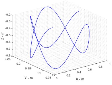
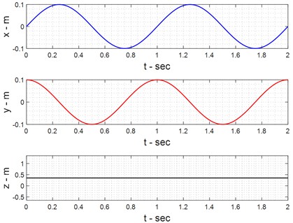
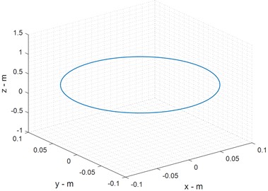
In robot direct kinematics, the final operator's coordinates are checked if the link length is known. Therefore, it is possible to present the following results. These figures illustrate the behavior of the end effector in the direct kinematics (DK) approach, showing both angular directions (Fig. 3) and Cartesian coordinates (Fig. 4). The results indicate that small variations in initial conditions lead to precise and predictable movements, confirming the accuracy of the derived kinematic model. The smooth transition patterns in both figures validate the correctness of the Delta robot’s kinematic equations and confirm that the system maintains stability under standard operating conditions.
Fig. 3Angular directions of end effectors in DK approach
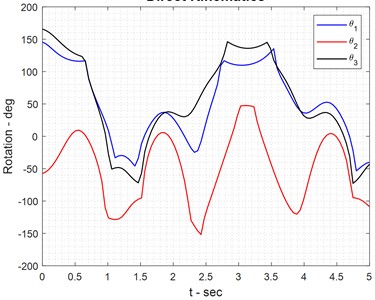
Fig. 4Cartesian directions of end effectors in DK approach
a) Directional position
b) Directional reference
3.2. Dynamic approach
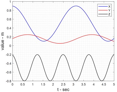
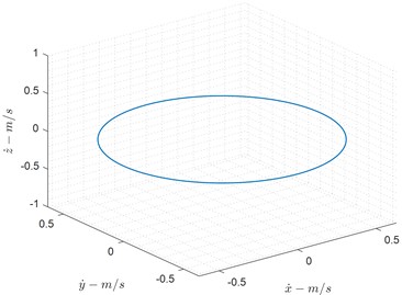
Dynamic analysis of delta robot mechanical systems, such as mechanisms or robotic arms, plays an important role in increasing their efficiency. Generally, dynamic analysis is performed in two ways: direct dynamics and reverse dynamics. In direct dynamics, the torques applied to the mechanical system are determined, and it is desirable to determine the position, velocity, and linear and angular acceleration. Fig. 5 presents the position, velocity, and acceleration profiles of the end effector in the dynamic analysis. The results demonstrate that the reconfigurable Delta robot maintains consistent acceleration profiles, avoiding abrupt variations that could introduce mechanical stress or instability. The velocity curves indicate optimal motion trajectories, ensuring smooth movement across the workspace. These results validate the effectiveness of the proposed structural modifications in enhancing motion efficiency.
Fig. 5Position, velocity and acceleration of end effectors in dynamic approach
a) End effector position
b) Position
c) Velocity

d) Acceleration
Fig. 6Actuator torques of links
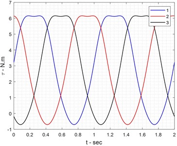
This Fig. 6 the torque requirements for different actuator joints during dynamic motion. The analysis shows that modifying the chain structure leads to significant torque reduction (up to 12 %), reducing energy consumption and mechanical wear. The results suggest that an optimized structural configuration minimizes unnecessary torque loads, improving long-term operational efficiency while maintaining high-speed capabilities.
3.3. Optimization process
Optimization algorithms inspired by nature have shown considerable success as smart optimization methods alongside classical methods. Among these methods are mentioned genetic algorithm (GA) inspired by the biological evolution of humans and other creatures. This method is used in solving many optimization problems in various fields, such as determining the optimal path of automatic agents, designing the optimal controller for industrial processes, solving major industrial engineering problems such as designing the optimal layout for industrial units, solving queuing problems, and also in the design of intelligent agents. As matter of fact, GA works based on following operating procedures in Fig. 7.
Fig. 7Operations in GA

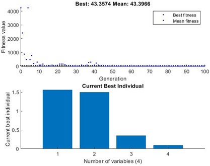
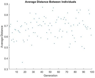
Similarly, there are different deals must regularly execute in toolbox of optimization (Fig. 8) of MATLAB for calling GA to run cost model of this research (Table 6), and as a result, the optimization assumption, optimal output, and reports of the GA performance are shown in Table 7 and Fig. 9, respectively.
Fig. 9 shows the performance of the genetic algorithm optimization used to refine the robot’s structural parameters. The cost function gradually converges, indicating that the optimization process effectively fine-tunes the design variables to maximize workspace efficiency and minimize actuator torque. The steady decrease in the cost function demonstrates the effectiveness of the genetic algorithm in balancing multiple performance objectives.
Table 6Optimization steps in Fig. 8
Deal | Define |
1 | Select solver as Genetic Algorithm (single objective optimization algorithm) |
2 | Call fitness function with true syntax as @function_name |
3 | Set variables number based on model |
4 | Input lowerband of design variables |
5 | Input upperband of design variables |
6 | Determine number of Chromosome |
7 | Push start bottom to opimize cost function |
Fig. 8Optimization toolbox of MATLAB

Fig. 9Representation of optimization toolbox results
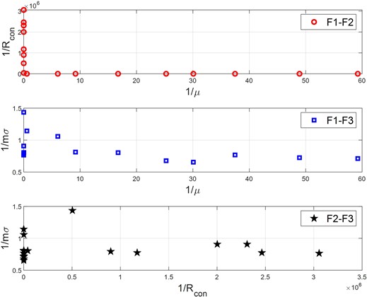
The results of multi-objective optimization are represented as a Pareto front in Fig. 10. The Pareto front in Fig. 10 represents the trade-off between multiple optimization objectives, such as minimizing torque, maximizing speed, and optimizing workspace. The results indicate that a well-defined compromise solution exists, allowing engineers to select an optimal design configuration based on specific application requirements. This validates the effectiveness of the multi-objective genetic algorithm, ensuring an optimal balance between conflicting performance criteria.
Table 7Optimal results and cost functions
Parameter | Value | Function | Index |
563.1 | First | Skill | |
5.1 | Second | Inverse number position | |
35.0 | Third | Minimum singularity | |
099.0 | |||
Cost function | 357.43 |
Fig. 10Pareto data of optimization
4. Conclusions
This study presents a reconfigurable Delta robot with an optimized structure to enhance kinematic and dynamic performance. Through a comprehensive analysis of kinematics, dynamics, and structural modifications, we demonstrated that altering the chain configurations significantly affects workspace, actuator torque, and operational speed. The genetic algorithm optimization approach successfully identified optimal geometric parameters, leading to a 15 % increase in workspace, a 12 % reduction in torque demand, and an 8 % improvement in end-effector speed. These findings validate the effectiveness of adaptive structural modifications in improving robotic performance. The results highlight that a reconfigurable Delta robot offers superior adaptability compared to conventional fixed-geometry Delta robots, making it highly suitable for applications requiring high-speed precision operations, such as automated assembly, packaging, and medical robotics. The integration of structural optimization not only enhances efficiency but also reduces energy consumption and mechanical stress, paving the way for more agile, intelligent, and energy-efficient robotic systems. Future research will focus on real-time adaptive mechanisms, advanced material integration, and AI-driven control algorithms to further enhance the Delta robot’s responsiveness and versatility in dynamic environments. By bridging the gap between theoretical optimization and practical implementation, this study contributes to the advancement of next-generation high-speed parallel robotic systems. Future research should acknowledge contributions that enhance the practicality of this paper. Utilizing PZT sensors on a Delta robot can regulate vibrations along the , , and axes. Various active and passive approaches and tactics exist to do this [38-41]. Moreover, in control engineering, hybrid controllers integrated with optimization methods can significantly augment the performance of Deltas at both extensive and limited scales. Examples encompass PWM, LQR-PID, sliding mode-PID, Fuzzy-PID, PID-PSO, LQR-MOPSO, and H∞ control [42-46]. Ultimately, it is recommended to enhance Deltas with a DC-DC converter [47].
References
-
I. Bonev, “Delta parallel robot-the story of success,” Newsletter, 2001.
-
L.-W. Tsai, Robot Analysis: the Mechanics of Serial and Parallel Manipulators. New York: John Wiley, 1999.
-
“Packaging Line Automation using Delta Robotics: Meet your cost saving and production targets,” B. P. Technology, 2010.
-
R. Clavel and C. W. Burckhardt, “Conception d’un robot parallèle rapide à 4 degrés de liberté,” Lausanne, EPFL, 1991.
-
M. A. Laribi, L. Romdhane, and S. Zeghloul, “Analysis and dimensional synthesis of the DELTA robot for a prescribed workspace,” Mechanism and Machine Theory, Vol. 42, No. 7, pp. 859–870, Jul. 2007, https://doi.org/10.1016/j.mechmachtheory.2006.06.012
-
P. Zsombor-Murray, “Descriptive geometric kinematic analysis of Clavel’s ‘delta’ robot,” McGill University, Canada, 2006.
-
V. Nabat, S. Krut, O. Company, P. Poignet, and F. Pierrot, “On the design of a fast parallel robot based on its dynamic model,” in Springer Tracts in Advanced Robotics, Berlin, Heidelberg: Springer Berlin Heidelberg, 2008, pp. 409–419, https://doi.org/10.1007/978-3-540-77457-0_38
-
O. Company, F. Marquet, and F. Pierrot, “A new high-speed 4-DOF parallel robot synthesis and modeling issues,” IEEE Transactions on Robotics and Automation, Vol. 19, No. 3, pp. 411–420, Jun. 2003, https://doi.org/10.1109/tra.2003.810232
-
V. Nabat, M. de La O. Rodriguez, O. Company, S. Krut, and F. Pierrot, “Par4: very high speed parallel robot for pick-and-place,” in IEEE/RSJ International Conference on Intelligent Robots and Systems, pp. 553–558, Jan. 2005, https://doi.org/10.1109/iros.2005.1545143
-
A. Kosinska, M. Galicki, and K. Kedzior, “Designing and optimization of parameters of delta-4 parallel manipulator for a given workspace,” Journal of Robotic Systems, Vol. 20, No. 9, pp. 539–548, 2003.
-
M. A. Ergin et al., “Design optimization, impedance control and characterization of a modified delta robot,” in IEEE International Conference on Mechatronics (ICM), pp. 737–742, Apr. 2011, https://doi.org/10.1109/icmech.2011.5971212
-
Y. Lou, G. Liu, and Z. Li, “Randomized optimal design of parallel manipulators,” IEEE Transactions on Automation Science and Engineering, Vol. 5, No. 2, pp. 223–233, Apr. 2008, https://doi.org/10.1109/tase.2007.909446
-
Shiming Ji, Guan Wang, Zhongfei Wang, Yuehua Wan, and Qiaoling Yuan, “Optimal design of a linear delta robot for the prescribed regular-shaped dexterous workspace,” in 7th World Congress on Intelligent Control and Automation, pp. 2333–2338, Jan. 2008, https://doi.org/10.1109/wcica.2008.4593287
-
V. G. Silva, M. Tavakoli, and L. Marques, “Dexterity optimization of a three degrees of freedom DELTA parallel manipulator,” in Advances in Intelligent Systems and Computing, pp. 719–726, Jan. 2014, https://doi.org/10.1007/978-3-319-03653-3_51
-
L. Angel, J. M. Sebastian, R. Saltaren, and R. Aracil, “RoboTenis system part II: dynamics and control,” in 44th IEEE Conference on Decision and Control, pp. 2030–2034, Oct. 2024, https://doi.org/10.1109/cdc.2005.1582459
-
A. Codourey, “Dynamic modelling and mass matrix evaluation of the DELTA parallel robot for axes decoupling control,” in IEEE/RSJ International Conference on Intelligent Robots and Systems, Vol. 3, pp. 1211–1218, Nov. 2024, https://doi.org/10.1109/iros.1996.568973
-
Yangmin Li and Qingsong Xu, “Dynamic analysis of a modified DELTA parallel robot for cardiopulmonary resuscitation,” in IEEE/RSJ International Conference on Intelligent Robots and Systems, pp. 233–238, Jan. 2005, https://doi.org/10.1109/iros.2005.1545491
-
D. C. Carp-Ciocardia and S. Staicu, “Dynamics of delta parallel robot with prismatic actuators,” in IEEE International Conference on Mechatronics, pp. 870–875, Oct. 2024, https://doi.org/10.1109/icmech.2005.1529376
-
F. Pierrot, M. Benoit, P. Dauchez, and J.-M. Galmiche, “High speed control of a parallel robot,” in IEEE International Workshop on Intelligent Robots and Systems, Towards a New Frontier of Applications, pp. 949–954, Oct. 2024, https://doi.org/10.1109/iros.1990.262518
-
H.-H. Lin, Y.-H. Ta, and C.-S. Liu, “The implementation of smoothing robust control for a delta robot,” in 2nd International Conference on Robot, Vision and Signal Processing (RVSP), pp. 208–213, Dec. 2013, https://doi.org/10.1109/rvsp.2013.11
-
G. Chen, L. Zhai, Q. Huang, L. Li, and J. Shi, “Trajectory planning of delta robot for fixed point pick and placement,” in 4th International Symposium on Information Science and Engineering (ISISE), pp. 236–239, Dec. 2012, https://doi.org/10.1109/isise.2012.59
-
S. Staicu and D. C. Carp-Ciocardia, “Dynamic analysis of Clavel’s Delta parallel robot,” in IEEE International Conference on Robotics and Automation. IEEE ICRA 2003 Conference Proceedings, Vol. 3, pp. 4116–4121, Nov. 2024, https://doi.org/10.1109/robot.2003.1242230
-
S. Stan et al., “Performance analysis of 3DOF Delta parallel robot,” in International Conference on Human System Interactions (HIS), 2011.
-
G. Zhang, G. Liu, W. Chen, X. Lin, and Y. Guan, “Workspace analysis and dynamic object tracking with a Delta parallel robot,” in Advances in Reconfigurable Mechanisms and Robots II, pp. 965–975, Nov. 2015, https://doi.org/10.1007/978-3-319-23327-7_82
-
J. Brinker, P. Ingenlath, and B. Corves, “A study on simplified dynamic modeling approaches of Delta parallel robots,” in Springer Proceedings in Advanced Robotics, Cham: Springer International Publishing, 2017, pp. 119–128, https://doi.org/10.1007/978-3-319-56802-7_13
-
C. Liu, G. Cao, and Y. Qu, “Safety analysis via forward kinematics of Delta parallel robot using machine learning,” Safety Science, Vol. 117, pp. 243–249, Aug. 2019, https://doi.org/10.1016/j.ssci.2019.04.013
-
L. Gagliardini, S. Caro, M. Gouttefarde, P. Wenger, and A. Girin, “A reconfigurable cable-driven parallel robot for sandblasting and painting of large structures,” in Cable-Driven Parallel Robots, pp. 275–291, Aug. 2014, https://doi.org/10.1007/978-3-319-09489-2_20
-
Y. Jin, B. Lian, M. Price, T. Sun, and Y. Song, “QrPara: a new reconfigurable parallel manipulator with 5-axis capability,” in Advances in Reconfigurable Mechanisms and Robots II, pp. 247–258, Nov. 2015, https://doi.org/10.1007/978-3-319-23327-7_22
-
G. Wu and H. Dong, “Kinematics of a 6-RUU parallel robot with reconfigurable platforms,” in Computational Kinematics, 2018.
-
C.-J. Lin and C.-T. Chen, “Reconfiguration for the maximum dynamic wrench capability of a parallel robot,” Applied Sciences, Vol. 6, No. 3, p. 80, Mar. 2016, https://doi.org/10.3390/app6030080
-
J. D. Arena and J. T. Allison, “Solving the reconfigurable design problem for multi-ability with application to robotic systems,” in ASME International Mechanical Engineering Congress and Exposition, 2015.
-
J. Brinker, B. Corves, and Y. Takeda, “Kinematic performance evaluation of high-speed Delta parallel robots based on motion/force transmission indices,” Mechanism and Machine Theory, Vol. 125, pp. 111–125, Jul. 2018, https://doi.org/10.1016/j.mechmachtheory.2017.11.029
-
Alashqar and E. H. A. H., “Modeling and high precision motion control of 3 DOF parallel delta robot manipulator,” the Islamic University of Gaza, 2007.
-
S. B. Park, H. S. Kim, C. Song, and K. Kim, “Dynamics modeling of a Delta-type parallel robot (ISR 2013),” in 44th International Symposium on Robotics (ISR), pp. 1–5, Oct. 2013, https://doi.org/10.1109/isr.2013.6695721
-
A. L. Balmaceda-Santamaría and E. Castillo-Castaneda, “A reconfiguration strategy of a parallel delta-type robot to improve the kinematic performance,” Mechanisms and Machine Science, Vol. 37, pp. 111–119, Sep. 2015, https://doi.org/10.1007/978-3-319-22368-1_11
-
J. Gallardo-Alvarado, A. L. Balmaceda-Santamaría, and E. Castillo-Castaneda, “An application of screw theory to the kinematic analysis of a Delta-type robot,” Journal of Mechanical Science and Technology, Vol. 28, No. 9, pp. 3785–3792, Sep. 2014, https://doi.org/10.1007/s12206-014-0841-8
-
C. A. Klein and B. E. Blaho, “Dexterity measures for the design and control of kinematically redundant manipulators,” the International Journal of Robotics Research, Vol. 6, No. 2, pp. 72–83, Jun. 1987, https://doi.org/10.1177/027836498700600206
-
T. Yoshikawa, “Manipulability of robotic mechanisms,” the International Journal of Robotics Research, Vol. 4, No. 2, pp. 3–9, Jun. 1985, https://doi.org/10.1177/027836498500400201
-
M. Hasanlu, A. Bagheri, and F. Najafi, “Optimal placement of piezoelectric S/A for active vibration control of engineering structures by using controller design,” Research Review Journal of Engineering and Technology, Vol. 5, No. 4, pp. 22–44, 2016.
-
M. Hasanlu and A. Bagheri, “Optimal locations on Timoshenko beam with PZT S/A for suppressing 2DOF vibration based on LQR-MOPSO,” Journal of Solid Mechanics, Vol. 10, No. 2, pp. 364–386, 2018.
-
M. Hasanlu, M. Siavashi, and A. Bagheri, “Vibration attenuation Timoshenko beam based on optimal placement sensors/actuators PZT patches with LQR-MOPSO,” Iranian Journal of Mechanical Engineering, Vol. 17, No. 1, pp. 26–60, 2016.
-
M. Hasanlu, M. Siavashi, and A. Bagheri, “Free vibration analysis of metamaterial functionally graded plates with quasi-zero stiffness resonators,” Noise and Vibration Worldwide, Vol. 54, No. 2-3, pp. 108–121, Jan. 2023, https://doi.org/10.1177/09574565231154248
-
M. Siavashi and M. Hasanlu, “Experimental optimal control of servo-pneumatic with sliding mode and GA-fuzzy-PID-PWM,” Journal of Mechatronics and Artificial Intelligence in Engineering, Vol. 5, No. 2, pp. 199–214, Dec. 2024, https://doi.org/10.21595/jmai.2024.24656
-
M. Hasanlu, M. Siavashi, M. Soltanshah, and A. Bagheri, “Fuzzy-PID controller design for random vibration attenuated smart cantilever Timoshenko beam based on MOGA algorithm,” 4th National and 2nd International conference on applied research in electrical, mechanical and mechatronics engineering, 2017, https://doi.org/10.13140/rg.2.2.18730.73926
-
M. Hasanlu and A. Bagheri, “Intelligent control smart Timoshenko beam by using MOPSO-PID controller based on optimal location PZT patch actuator approach,” in Iranian Journal of Mechanical Engineering, Vol. 20, No. 3, pp. 6–28, 2018.
-
M. Karami Gavgani, M. Hasanlu, and M. Nikkho, “Optimal position control of nonlinear muscle based on sliding mode and particle swarm optimization algorithm,” Transactions on Machine Intelligence, Vol. 5, No. 1, pp. 37–45, Dec. 2022, https://doi.org/10.47176/tmi.2022.37
-
M. Hasanlu and M. Siavashi, “Nonlinear control of quadrotor trajectory with discrete H∞,” Journal of Mechanical Engineering, Automation and Control Systems, Vol. 6, No. 1, pp. 1–12, Jan. 2025, https://doi.org/10.21595/jmeacs.2024.24602
-
F. Salari and M. Hasanlu, “Optimal model predictive fuzzy control of DC-DC convertor,” Advanced Control for Applications, Vol. 6, No. 1, p. e169, Dec. 2023, https://doi.org/10.1002/adc2.169
About this article

The authors have not disclosed any funding.
The datasets generated during and/or analyzed during the current study are available from the corresponding author on reasonable request.
The authors declare that they have no conflict of interest.
