Abstract
This paper presents a co-simulation of MATLAB and CarSim to control and model a vehicle suspension system under different road surface conditions, either wet or dry, using an active fuzzy controller in MATLAB. CarSim is a professional vehicle simulation software capable of modeling nonlinear car dynamics with various uncertainties. These uncertainties are addressed by the fuzzy set approach due to its qualitative and robust control capabilities, effectively handling noise, disturbances (such as road conditions), and unknown parameters in CarSim’s vehicle model. The design of an active steering controller and rotational torque system using a fuzzy controller is crucial for enhancing road safety, especially given the increasing number of vehicle crashes. The research methodology varies based on the study's purpose, nature, and implementation capabilities. Accordingly, this research focuses on designing an integrated controller for an active four-wheel-drive system and direct rotary torque control using a fuzzy control method in the MATLAB Simulink environment. This study is analytical and functional, utilizing CarSim for simulation. A fuzzy logic-based integrated control system was designed for steady-state control to improve vehicle stability and steering. The controller adjusts the steering angle and torque to regulate the vehicle’s angular velocity and slip angle under various conditions. As tire performance changes during different maneuvers, the controller dynamically adapts its output to maintain optimal operation within the effective performance range. The significance of using fuzzy logic lies in its ability to handle non-linearity without requiring approximation, ensuring high accuracy. Additionally, it delivers excellent results in enhancing vehicle stability. The findings indicate that the controller significantly improves the vehicle’s dynamic behavior across different driving maneuvers compared to an uncontrolled vehicle.
Highlights
- Innovative Use of Fuzzy Logic for Vehicle Control
- Co-Simulation Framework with MATLAB and CarSim
- Integrated Control for Enhanced Stability and Handling
- Adaptability to Diverse Road Conditions
- Improved Vehicle Dynamics Demonstrated in Simulations
1. Introduction
Analytical and numerical methods simulate car behavior as a dynamic system, focusing on factors such as spring stiffness, shock absorber damping, anti-roll stiffness, tire dynamics, suspension systems, vehicle geometry, mass characteristics, power transmission systems, and steering systems. Control systems like four-wheel steerability, rear-wheel steerability, anti-lock braking systems, thrust force control, acceleration control, and roll stiffness distribution enhance vehicle stability. The active steering controller and fuzzy controller methods improve safety and stability, reducing accident risks and enhancing vehicle response to driver input [1]. A study utilizing a predictive model controller for the ALSD rear differential system demonstrated superior performance compared to a sliding-mode controller in a ten-degree-of-freedom model simulation [2]. The vehicle's dynamic system, which controls the sideslip angle and rotational angular velocity, requires rotational torque from the DYC system and a steering correction angle from the 4WS [3]. Advanced active stability and safety control systems enhance stability and control by considering tire non-linearity and road conditions, improving vehicle dynamics under various driving conditions [4]. Vehicle dynamics theory suggests that two inputs – rotational torque from the DYC system and a steering correction angle from the 4WS system – are required simultaneously to maintain vehicle stability and path control [5]. One of the key features of the designed control rules is their ability to account for the nonlinear effects and uncertainties in the vehicle dynamics model [6]. The study aimed to improve car handling characteristics by coordinating rotational torque control systems and active steering angles, solving adaptive optimization problems to determine optimal rotational and brake torque values [7]. The most effective method for car stability is the direct application of rotational torque by controlling longitudinal forces on the vehicle's sides, while indirect lateral force control limits torque and speed. A fuzzy control method enhances steering performance and increases transverse stability [8]. In their research, a Sliding Mode Controller was designed for the active differential system to control the vehicle's rotational stability. Simulations using CarSim software demonstrated that the designed control increased vehicle stability during cornering acceleration [9]. To develop adaptive and robust controllers for vehicle dynamics control, researchers combined sliding mode control with fuzzy logic, improving performance, reducing vibration, and enhancing steering characteristics. This approach also addresses the need for comprehensive knowledge of road conditions and friction coefficients [10]. SMC controllers improved anti-lock braking performance and vehicle stability across various road conditions compared to ABS without SMC [11]. Fuzzy-sliding mode control (FSMC), a combination of sliding mode control and fuzzy logic, enhances slip control and resistance, making it an effective control method [12]. Sliding mode control (SMC) provides invariance to adaptive uncertainty, making it a powerful tool for addressing structured or unstructured uncertainties, disturbances, and noise [13]. For improved integrated control and rotational stability of fully electric vehicle chassis, a multi-layered control structure is utilized. A sliding mode control method further enhances performance, and driver behavior is also modeled for greater realism [14]. To improve the stability of car dynamics and address challenges arising from vehicle modeling and nonlinear tire dynamics, optimization methods prove useful [15]. Other robust control methods, such as μ and √H synthesis, have been employed in front-wheel steering control due to tire model non-linearity and parameter uncertainties [16]. Similarly, a structure based on H∞-resistant linear parameter variation (LPV) has been developed to optimize vehicle torque, enabling four-wheel drive capability [17]. A novel approach for reducing derailment in articulated heavy-duty vehicles enhances maneuverability and prevents uncontrolled rotation through a fuzzy logic-based control system that adjusts the joint angle [18]. While articulated vehicles offer economic benefits by allowing greater cargo transport at lower costs, their increased height reduces maneuverability, complicating movement on narrow roads and small streets [19]. Research has focused on improving the maneuverability and stability of articulated vehicles due to their complex dynamic structures and higher centers of gravity [20]. The study explores designing an active steering controller and rotational torque control using a fuzzy controller method to enhance stability and improve turning performance in heavy vehicles [21]. Researchers have developed ADAS for low-speed bus braking, reducing collisions and pedestrian accidents by detecting collisions, sending emergency signals, and improving reaction times [22]. The proposed autonomous driving system features robust safety measures, efficient communication, and low-level control algorithms, utilizing a Python-based high-fidelity simulation system for evaluation [23]. Research on active front-wheel steering control using predictive control methods demonstrates improved performance in tracking optimal rotary motion models [24]. The research examines fuzzy controller design in a two-wheeled vehicle model, focusing on steering and dynamics. Controller performance is evaluated by matching the vehicle's dynamic behavior with the desired behavior, with the rear wheel's steering angle (ASC) as the output [25]. Another study analyzes the impact of an active differential on steering smoothness in a four-wheel drive vehicle using a dynamic model with eight degrees of freedom. The differential system controls torque distribution between wheels. Simulations in Simulink MATLAB using a fuzzy control strategy show improved vehicle behavior when applied to both axles but less efficiency when the center of mass is closer to the center [26], [27], [28]. A fuzzy-neural adaptation of the ANFSMC sliding model is used to control the full active suspension system. ANFSMC adapts to online dynamic estimation, providing feedback responses [29]. The ANFIS controller integrates ABS and suspension systems using a T-S fuzzy neural network structure, reducing stopping time and distance while incorporating classical proportional-derivative rules [30]. Active steering systems, a widely studied method for controlling rotational vehicle stability, adjust steering angles based on side dynamics and driver preferences. These systems include AFS, ARS, and A4WS. Research indicates that front-wheel systems are the most effective and economical, with superposition angle adjustments improving comfort and efficiency [31], [32]. The AFS system employs a rack-and-pinion hydraulic steering mechanism with a mechatronic actuator. A planetary gear set, worm gear, and worm wheel system control the steering pinion’s angle, which equals the steering wheel’s angle plus the electric motor's correction angle [33]. The study aims to improve road safety by designing an integrated controller for active four-wheel drive systems and direct rotary torque control using a fuzzy controller. The research methodology combines analytical analysis with functional simulation using CarSim software. The integrated control system employs steady-state control, adjusting the steering angle and torque to regulate vehicle angular velocity and slip angle. To optimize tire performance under varying driving conditions, the controller dynamically adjusts its output. A key advantage of this controller is its ability to handle non-linearity without approximation, ensuring high accuracy. The results demonstrate that the controller effectively maintains vehicle stability across different maneuvers and significantly enhances dynamic performance compared to an uncontrolled vehicle.
2. Methodology
The presented mathematical model describes a vehicle moving at a constant speed on a rough road with seven degrees of freedom. As shown in Fig. 1, the car’s suspension system is schematically represented with seven degrees of freedom.
Fig. 1Full model of suspension vehicle: a) side view, b) up view
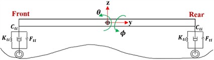
a)
b)
The complete mathematical model of the car can be expressed as the following Eq. (1):
Eq. (1) is fundamental to this study as it represents the relationship between damping coefficients, vertical displacements, and tire forces – critical parameters in vehicle suspension dynamics. By including Eq. (1), a mathematical foundation is established for understanding how forces interact within the suspension system, directly influencing vehicle stability and handling. This Eq. (1) is essential for demonstrating the role of the fuzzy controller in dynamically adjusting the suspension response to varying road conditions. Without this formulation, validating the effectiveness of the proposed control system in improving ride comfort and safety would be challenging. Therefore, presenting Eq. (1) strengthens the technical rigor of this study and provides a necessary basis for subsequent control design and simulation analysis. To clarify the parameters of Eq. (1), they are presented in Table 1.
Table 1Parameters on Eq. (1)
Parameter | Define | |||
Displacement of | front | left-side | of suspension’s mass point | |
rear | ||||
front | right-side | |||
rear | ||||
Vertical displacement of tyers | ||||
Roll angle | ||||
Pitch angle | ||||
Damping coefficients | ||||
Disturbance | ||||
Vertical force of tyers | ||||
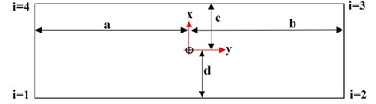
Table 2Indexation of wheels
Index number | Wheel direction |
1 | Front right |
2 | Rear right |
3 | Front left |
4 | Rear left |
The subscripts of the vector components , , and can be described in Table 2.
As shown in Eq. (2) that show the effect of spring, damper, and tire mass for each wheel:
It can illustrate the constant parameters of the above relationships in the form of the following Table 2.
Table 3Parameters on Eq. (2)
Symbol | Define |
Mass suspension | |
Damping coefficient of suspension | |
Gravitational acceleration | |
Stiffness of suspension | |
Stiffness of tyer | |
Suspension’s force |
The vehicle’s vertical movement can be expressed as follows:
In Eq. (3), is the mass of the car. The angular motion of the entire car roll can be expressed as Eq. (4):
The Eq. (5) represents the angular movement of the entire screw in the car suspension system:
Table 4Parameters on Eq. (5)
Symbol | Define | ||
Distance between suspension’s mass point and | front | side of axle | |
rear | |||
right | |||
left | |||
Roll | moment inertia | ||
Pitch | |||
Regarding the fixed parameters, the following can be presented in Table 4.
And the parameters , , and in Eq. (6) can be described as follows:
3. Fuzzy controller
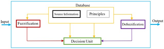
A fuzzy controller consists of four main components: the fuzzifier, rule base, decision-making unit, and defuzzifier. Fig. 2 provides an overview of the fuzzy controller, which is explained in detail in the following sections.
Fig. 2Block diagram of fuzzy processing
4. Result and discussion
The simulation results in this section are divided into three parts: the results from CarSim, the vehicle system control model, and the fuzzy controller. All relevant results are presented comprehensively. The simulation section discusses the design steps and the extraction of results from both CarSim and Simulink software. CarSim provides a realistic suspension system model, which is then transferred to the Simulink environment to design a suitable controller for maintaining system stability, as demonstrated in the following steps.
4.1. Fuzzy control
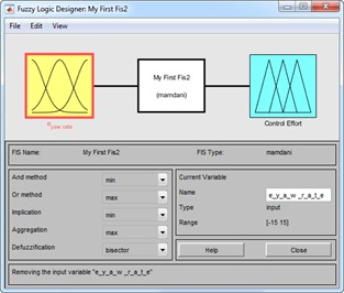
A system that maps inputs to outputs using phase logic is known as a fuzzy inference system (FIS). FIS is also called a rule-based system because it consists of multiple 'if-then' statements. When applied to control systems, it is referred to as a fuzzy controller. The main architecture of an FIS consists of five functional blocks, as shown in Fig. 3:
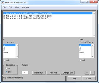
1) Rule base: Contains fuzzy “if-then” rules and expressions.
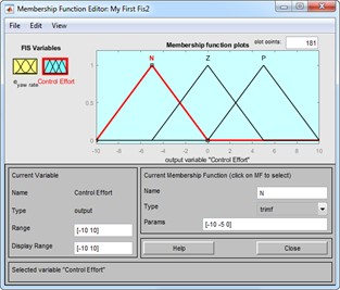
2) Database: Defines membership functions.
3) Decision-making unit: Performs operations on fuzzy rules.
4) Fuzzification interface: Converts real inputs into fuzzy sets.
5) Defuzzification interface: Converts fuzzy results into real values.
Inputs:
1) Brake pressure applied to the front wheels.
2) Steering angle of the rear wheels.
Output:
1) Error in the rate of change of yaw rotation (yaw rate) of the vehicle.
The following section reviews the fuzzy controller design process.
Fig. 3Fuzzy set: a) inputs, b) input membership, c) output membership, d) fuzzy rule, e) fuzzification process, f) fuzzy surface control
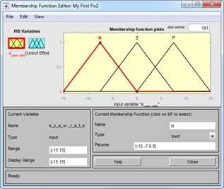
a)
b)
c)
d)
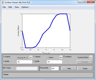
e)
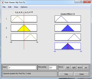
f)
The control rules consist of a series of conditional and logical expressions that relate the input and output membership functions of the fuzzy controller. These rules are illustrated in the following images. As mentioned earlier, the relationship between the controller’s input and output levels can be seen in Fig. 4.
Fig. 4Car in opened loop model: a) slip tyers, b) automobile handling, c) longitudinal force of tyers
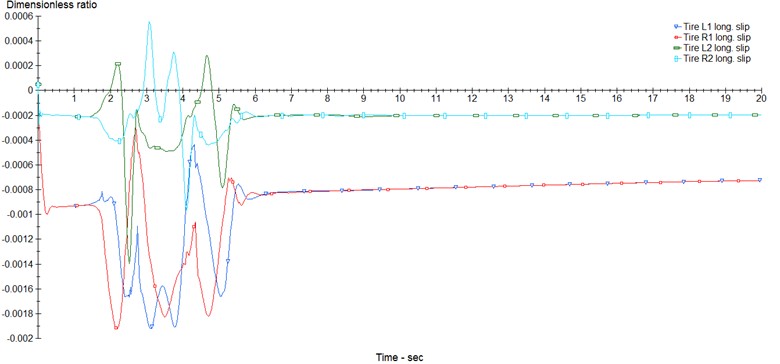
a)
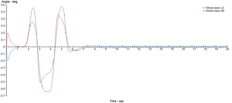
b)
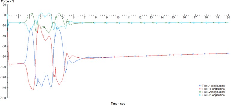
c)
4.2. CarSim
In this section, the structural modeling of the car is evaluated based on its input, output, geometric and dynamic characteristics, car type, and other design-related features. The following images illustrate the modeling process of the control analysis for the desired vehicle. The proposed models in this study focus on analyzing steering, braking, and integrated control (braking and steering simultaneously) under both dry and wet road conditions. A total of six models are proposed, which will be discussed in the subsequent section of images related to the control results of the car system. To simulate the two road states – dry and wet – with friction coefficients of 0.85 and 0.5, as shown in the image below, the proposed models are analyzed and tested. In the next two images, the required inputs and outputs for the fuzzy controller for the car are selected. The simulation in CarSim is open-loop, and three key parameters for steering control, braking, and overall integrated control are presented as examples: tire slippage, car steering angle, and longitudinal force of the car tires.
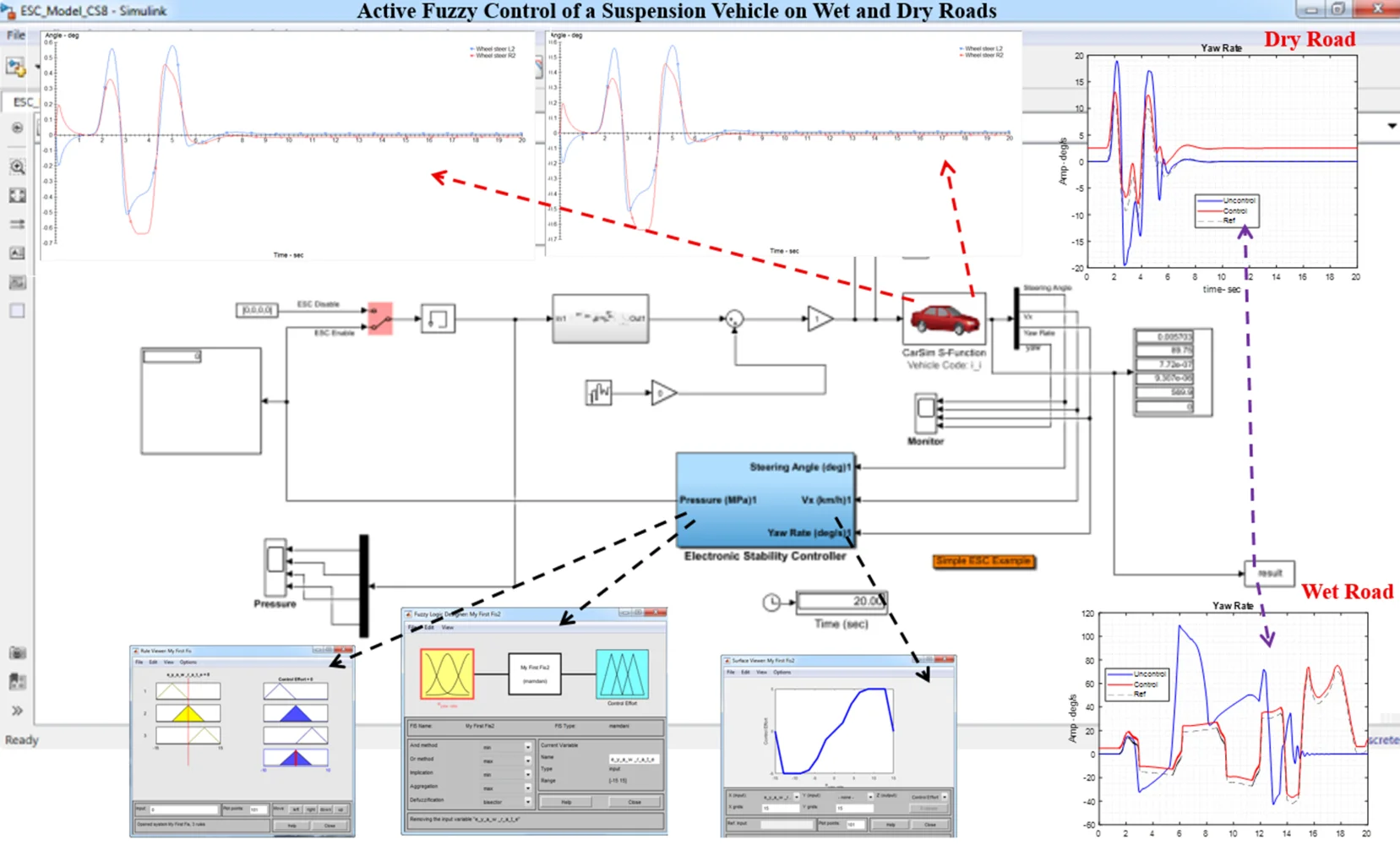
After configuring the car's input, output, and other characteristics, the built model is transferred into the Simulink MATLAB environment. In Fig. 5, a closed-loop control system is shown, which illustrates the application of the design made in the fuzzy controller.
.
Fig. 5Co-simulation CarSim and MATLAB on Simulink
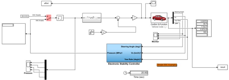
This section discusses the use of MATLAB calculation software, which utilizes the Simulink environment to build the model and imports it into the CarSim software. By identifying the vehicle system's inputs and outputs, the simulation of the fuzzy controller design is initiated. As mentioned earlier, the six models proposed in this research are categorized into two types: dry road (with a friction coefficient of 0.85) and wet road (with a friction coefficient of 0.5). Each category features three control modes: steering control, braking control, and integrated control. The controllability and braking performance have been evaluated, and the results from the simulation are presented below.
4.3. Dry road
It is assumed that a dry road has a friction coefficient of 0.85, as shown in Fig. 6. In this model, three modes – steering-only, braking-only, and integrated control based on fuzzy controllers – will be simulated.
4.3.1. Car steering on dry road
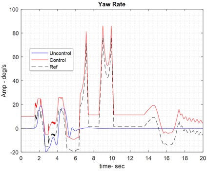
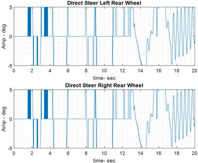
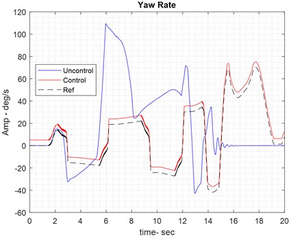
The proposed models provide graphs for all three modes in each category, including yaw rate, control effort, and vehicle movement path. These graphs display the reference yaw rate, along with the yaw rate both with and without the controller, to highlight the effect of the fuzzy controller. The control effort represents the output of the fuzzy controller and serves as the input to the vehicle plant for controlling the vehicle system. Since the full model analyzes the steering of the car, the control effort in this analysis refers to the rotation angle of the car’s rear tires while it is on the road (see Fig. 6).
Fig. 6Results of handling control on dry road
4.3.2. Car breaking on dry road
The process of analyzing car braking on a dry road follows a similar approach to the car control process described in the previous section. In the image below (Fig. 7), the yaw rate is shown during the period when braking pressure, acting as a control effort, is applied to the front wheels of the car.
Fig. 7Results of braking control on dry road
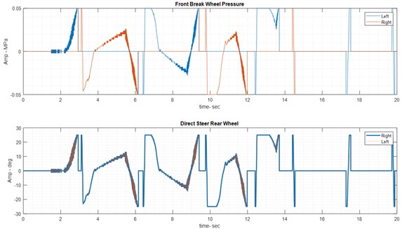
As mentioned earlier, the integrated analysis of simultaneous braking on the front wheels also considers the rotation angle applied to the rear wheels. Fig. 8 shows the car in its state with and without the speed assist controller, where the control effort now represents the combined effect of the braking pressure on the front wheels and the rotation angle applied to the rear wheels.
Fig. 8Results of integrated control on dry road
4.4. Wet road
The only structural difference in the wet road model is the coefficient of friction applied to the road, which is set to 0.5 (see Fig. 9). In this proposed model, similar to the previous one, three modes – steering, braking, and integrated control – have been simulated. The results for all three modes can be seen in the following images.
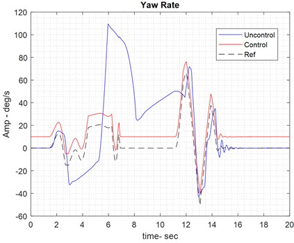
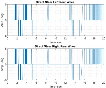
4.4.1. Handling analysis on wet road
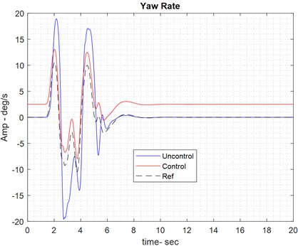
In the wet road mode, the car’s steering is controlled through the rotation angle of the rear wheels, as shown in both the controlled and non-controlled states in Fig. 9. These images also illustrate the control effort in the steering mode on the wet road, specifically showing the rear wheel rotation of the car.
Fig. 9Results of handling control on wet road
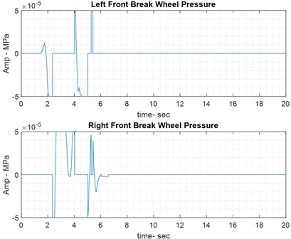
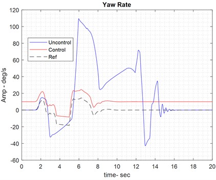
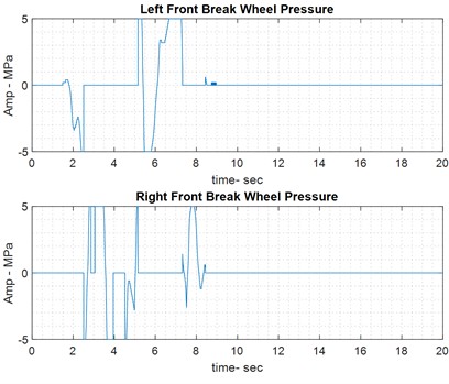
4.4.2. Car breaking on wet road
The front wheels are used for braking in the car. On the wet road, the fuzzy controller effectively tracks the reference yaw rate. To achieve the red trajectory in the previous image, control effort – specifically the brake pressure applied to the front wheels – must be exerted to guide the car along the reference yaw rate path.
Fig. 10Results of braking control on wet road
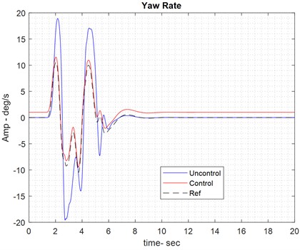
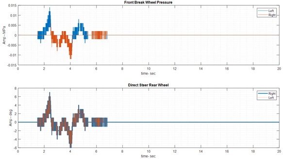
4.4.3. Integrated analysis on wet road
The integrated analysis on the wet road is the final simulation result of this research. The results are similar to those of previous simulations and are shown in Fig. 11. This analysis also highlights the control effort required, which includes the application of brake pressure to the front wheels and the adjustment of the rear wheels’ rotation angle in the car.
Fig. 11Results of integrated control on wet road
5. Conclusions
This study focused on designing an integrated controller for a four-wheel active steering system and direct rotational torque control using fuzzy logic. Through modeling and simulation, the proposed controller demonstrated its effectiveness in improving vehicle stability and handling on both wet and dry roads. The results indicate that the controller successfully regulates the steering angle and torque, maintaining vehicle stability during various maneuvers. A key advantage of the fuzzy controller is its ability to handle system non-linearity without requiring approximation, ensuring high accuracy and responsiveness. The fuzzy logic-based approach allows for real-time adaptation to changing road conditions, optimizing tire performance and vehicle dynamics. The simulation results further validate the controller’s ability to enhance driving safety and overall performance compared to an uncontrolled system. Overall, this research highlights the benefits of integrating fuzzy logic into vehicle control systems, offering a robust solution for improving road handling and stability. Future work could focus on real-world testing and further optimization to refine controller performance under diverse driving conditions. Subsequent studies should recognize contributions that augment the applicability of this paper. The application of PZT sensors on a suspension model can control vibrations along the , , and axes. Diverse active and passive methodologies and strategies are available to achieve this [34], [35-37]. Furthermore, in control engineering, hybrid controllers combined with optimization techniques can substantially enhance the performance of suspension systems on both large and small scales. Examples include PWM, LQR-PID, sliding mode-PID, Fuzzy-PID, PID-PSO, LQR-MOPSO, and H∞ control [38-42]. It is advisable to augment the vehicle or suspension with a DC-DC converter [43].
References
-
A. G. Zadeh, A. Fahim, and M. El-Gindy, “Neural network and fuzzy logic applications to vehicle systems: literature survey,” International Journal of Vehicle Design, Vol. 18, No. 2, pp. 132–193, 1997.
-
D. Rubin and S. A. Arogeti, “Vehicle yaw stability control using active limited-slip differential via model predictive control methods,” Vehicle System Dynamics, Vol. 53, No. 9, pp. 1315–1330, Sep. 2015, https://doi.org/10.1080/00423114.2015.1046461
-
Yuxiao Chen, Huei Peng, and J. Grizzle, “Decentralized chassis control with guaranteed performance: A lyapunov approach,” in American Control Conference (ACC), pp. 4291–4296, May 2017, https://doi.org/10.23919/acc.2017.7963615
-
A. Saikia and C. Mahanta, “Integrated control of active front steer angle and direct yaw moment using second order sliding mode technique,” in IEEE 1st International Conference on Power Electronics, Intelligent Control and Energy Systems (ICPEICES), pp. 1–4, Jul. 2016, https://doi.org/10.1109/icpeices.2016.7853059
-
H. Mirzaeinejad and M. Mirzaei, “Optimization of nonlinear control strategy for anti-lock braking system with improvement of vehicle directional stability on split-μ roads,” Transportation Research Part C: Emerging Technologies, Vol. 46, pp. 1–15, Sep. 2014, https://doi.org/10.1016/j.trc.2014.05.003
-
S. Yim, S. Kim, and H. Yun, “Coordinated control with electronic stability control and active front steering using the optimum yaw moment distribution under a lateral force constraint on the active front steering,” Proceedings of the Institution of Mechanical Engineers, Part D: Journal of Automobile Engineering, Vol. 230, No. 5, pp. 581–592, Jun. 2015, https://doi.org/10.1177/0954407015590037
-
M. H. Al-Mola, M. Mailah, P. M. Samin, A. H. Muhaimin, and M. Y. Abdullah, “Performance comparison between sliding mode control and active force control for a nonlinear anti-lock brake system,” WSEAS Transactions on Systems and Control, Vol. 9, No. 1, pp. 101–107, 2014.
-
D. Rubin and S. Arogeti, “Vehicle yaw stability control using rear active differential via sliding mode control methods,” in 21st Mediterranean Conference on Control and Automation (MED), pp. 317–322, Jun. 2013, https://doi.org/10.1109/med.2013.6608740
-
X. Yin, L. Pan, and S. Cai, “Robust adaptive fuzzy sliding mode trajectory tracking control for serial robotic manipulators,” Robotics and Computer-Integrated Manufacturing, Vol. 72, p. 101884, Dec. 2021, https://doi.org/10.1016/j.rcim.2019.101884
-
N. Raesian, N. Khajehpour, and M. Yaghoobi, “A new approach in anti-lock braking system (ABS) based on adaptive neuro-fuzzy self-tuning PID controller,” in 2011 2nd International Conference on Control, Instrumentation, and Automation (ICCIA), pp. 530–535, Dec. 2011, https://doi.org/10.1109/icciautom.2011.6356714
-
S. Mobayen, D. Baleanu, and F. Tchier, “Second-order fast terminal sliding mode control design based on LMI for a class of non-linear uncertain systems and its application to chaotic systems,” Journal of Vibration and Control, Vol. 23, No. 18, pp. 2912–2925, Feb. 2016, https://doi.org/10.1177/1077546315623887
-
P. Song, M. Tomizuka, and C. Zong, “A novel integrated chassis controller for full drive-by-wire vehicles,” Vehicle System Dynamics, Vol. 53, No. 2, pp. 215–236, Feb. 2015, https://doi.org/10.1080/00423114.2014.991331
-
H. Her, E. Joa, K. Yi, and K. Kim, “Integrated chassis control for optimized tyre force coordination to enhance the limit handling performance,” Proceedings of the Institution of Mechanical Engineers, Part D: Journal of Automobile Engineering, Vol. 230, No. 8, pp. 1011–1026, Aug. 2015, https://doi.org/10.1177/0954407015597794
-
J. Wu, Y. Zhao, X. Ji, Y. Liu, and L. Zhang, “Generalized internal model robust control for active front steering intervention,” Chinese Journal of Mechanical Engineering, Vol. 28, No. 2, pp. 285–293, Jan. 2015, https://doi.org/10.3901/cjme.2015.0106.006
-
R. Wang, H. Zhang, J. Wang, F. Yan, and N. Chen, “Robust lateral motion control of four-wheel independently actuated electric vehicles with tire force saturation consideration,” Journal of the Franklin Institute, Vol. 352, No. 2, pp. 645–668, Feb. 2015, https://doi.org/10.1016/j.jfranklin.2014.09.019
-
S. Shojaei, A. Rahmani Hanzaki, S. Azadi, and M. A. Saeedi, “A novel decision-making unit for automated maneuver of articulated vehicles in real traffic situations,” Proceedings of the Institution of Mechanical Engineers, Part D: Journal of Automobile Engineering, Vol. 234, No. 1, pp. 152–171, Apr. 2019, https://doi.org/10.1177/0954407019838380
-
A. M. C. Odhams, R. L. Roebuck, D. Cebon, and C. B. Winkler, “Dynamic safety of active trailer steering systems,” Proceedings of the Institution of Mechanical Engineers, Part K: Journal of Multi-body Dynamics, Vol. 222, No. 4, pp. 367–380, Dec. 2008, https://doi.org/10.1243/14644193jmbd174
-
G. Georgiou, A. Badarlis, and S. Natsiavas, “Modelling and ride dynamics of a flexible multi-body model of an urban bus,” Proceedings of the Institution of Mechanical Engineers, Part K: Journal of Multi-body Dynamics, Vol. 222, No. 2, pp. 143–154, Jun. 2008, https://doi.org/10.1243/14644193jmbd130
-
M. Iida, H. Nakashima, H. Tomiyama, T. Oh, and T. Nakamura, “Small-radius turning performance of an articulated vehicle by direct yaw moment control,” Computers and Electronics in Agriculture, Vol. 76, No. 2, pp. 277–283, May 2011, https://doi.org/10.1016/j.compag.2011.02.006
-
V. Girbes, L. Armesto, J. Dols, and J. Tornero, “An active safety system for low-speed bus braking assistance,” IEEE Transactions on Intelligent Transportation Systems, Vol. 18, No. 2, pp. 377–387, Feb. 2017, https://doi.org/10.1109/tits.2016.2573921
-
J. Lin and R.-J. Lian, “Hybrid self-organizing fuzzy and radial basis-function neural-network controller for active suspension systems,” International Journal of Innovative Computing Information and Control, Vol. 7, No. 6, pp. 3359–3378, 2011.
-
M. Wasim, A. U. Awan, A. Kashif, M. M. Khan, and M. Abbasi, “Predictive Control for improving vehicle handling and stability,” in 9th International Conference on Electrical and Electronics Engineering (ELECO), pp. 879–884, Nov. 2015, https://doi.org/10.1109/eleco.2015.7394581
-
Y. Cao and M. Qiao, “Application of fuzzy control in four wheel steering control system,” in International Conference on Advanced Mechatronic Systems (ICAMechS), pp. 62–66, Dec. 2017, https://doi.org/10.1109/icamechs.2017.8316551
-
M. Canale and L. Fagiano, “Comparing rear wheel steering and rear active differential approaches to vehicle yaw control,” Vehicle System Dynamics, Vol. 48, No. 5, pp. 529–546, May 2010, https://doi.org/10.1080/00423110902919055
-
A. Najari, F. Shabani, and M. Hosseynzadeh, “Integrated intelligent control system design to improve vehicle rotational stability using active differential,” Acta Technica Corviniensis – Bulletin of Engineering, Vol. 14, No. 1, pp. 79–82, 2021.
-
W.-Y. Wang, M.-C. Chen, and S.-F. Su, “Hierarchical T-S fuzzy-neural control of anti-lock braking system and active suspension in a vehicle,” Automatica, Vol. 48, No. 8, pp. 1698–1706, Aug. 2012.
-
G. Papaioannou and D. Koulocheris, “Multi-objective optimization of semi-active suspensions using KEMOGA algorithm,” Engineering Science and Technology, an International Journal, Vol. 22, No. 4, pp. 1035–1046, Aug. 2019, https://doi.org/10.1016/j.jestch.2019.02.013
-
Jiangtao Cao, Honghai Liu, Ping Li, and D. J. Brown, “State of the art in vehicle active suspension adaptive control systems based on intelligent methodologies,” IEEE Transactions on Intelligent Transportation Systems, Vol. 9, No. 3, pp. 392–405, Sep. 2008, https://doi.org/10.1109/tits.2008.928244
-
J. Ackermann, T. Bünte, and D. Odenthal, “Advantages of active steering for vehicle dynamics control,” The German Aerospace Center, Jan. 1999.
-
W. Klier, G. Reimann, and W. Reinelt, “Concept and functionality of the active front steering system,” in SAE technical paper, Jan. 2004.
-
R. Rajamani, Vehicle Dynamics and Control. Springer Science and Business Media, 2011.
-
F. Resta, G. Teuschl, M. Zanchetta, and A. Zorzutti, “A new control strategy for a semi-active differential (part II),” IFAC Proceedings Volumes, Vol. 38, No. 1, pp. 146–151, Jan. 2005, https://doi.org/10.3182/20050703-6-cz-1902.01912
-
G. Lechner and H. Naunheimer, Automotive Transmissions: Fundamentals, Selection, Design and Application. Springer Science & Business Media, 1999.
-
M. Hasanlu, A. Bagheri, and F. Najafi, “Optimal placement of piezoelectric S/A for active vibration control of engineering structures by using controller design,” Research and Reviews: Journal of Engineering and Technology, Vol. 5, No. 4, pp. 22–44, 2016.
-
M. Hasanlu and A. Bagheri, “Optimal locations on Timoshenko beam with PZT S/A for suppressing 2Dof vibration based on LQR-MOPSO,” Journal of Solid Mechanics, Vol. 10, No. 2, pp. 364–386, 2018.
-
M. Hasanlu, M. Siavashi, and A. Bagheri, “Vibration attenuation Timoshenko beam based on optimal placement sensors/actuators PZT patches with LQR-MOPSO,” Iranian Journal of Mechanical Engineering Transactions of the ISME, Vol. 17, No. 1, pp. 26–60, 2016.
-
M. Hasanlu, M. Siavashi, and A. Bagheri, “Free vibration analysis of metamaterial functionally graded plates with quasi-zero stiffness resonators,” Noise and Vibration Worldwide, Vol. 54, No. 2-3, pp. 108–121, Jan. 2023, https://doi.org/10.1177/09574565231154248
-
M. Siavashi and M. Hasanlu, “Experimental optimal control of servo-pneumatic with sliding mode and GA-fuzzy-PID-PWM,” Journal of Mechatronics and Artificial Intelligence in Engineering, Vol. 5, No. 2, pp. 199–214, Dec. 2024, https://doi.org/10.21595/jmai.2024.24656
-
M. Hasanlu, M. Siavashi, M. Soltanshah, and A. Bagheri, “Fuzzy-PID controller design for random vibration attenuated smart cantilever Timoshenko beam based on MOGA algorithm,” in 4th National and 2nd International Conference on Applied Research in Electrical, Mechanical and Mechatronics Engineering, 2017.
-
M. Hasanlu and A. Bagheri, “Intelligent control smart timoshenko beam by using MOPSO-PID controller based on optimal location PZT patch actuator approach,” Iranian Journal of Mechanical Engineering, Vol. 20, No. 3, pp. 6–28, 2018.
-
M. Karami Gavgani, M. Hasanlu, and M. Nikkho, “Optimal position control of nonlinear muscle based on sliding mode and particle swarm optimization algorithm,” Transactions on Machine Intelligence, Vol. 5, No. 1, pp. 37–45, Dec. 2022, https://doi.org/10.47176/tmi.2022.37
-
M. Hasanlu and M. Siavashi, “Nonlinear control of quadrotor trajectory with discrete H∞,” Journal of Mechanical Engineering, Automation and Control Systems, Vol. 6, No. 1, pp. 1–13, Jan. 2025, https://doi.org/10.21595/jmeacs.2024.24602
-
F. Salari and M. Hasanlu, “Optimal model predictive fuzzy control of DC-DC convertor,” Advanced Control for Applications, Vol. 6, No. 1, p. e169, Dec. 2023, https://doi.org/10.1002/adc2.169
About this article

The authors have not disclosed any funding.
The datasets generated during and/or analyzed during the current study are available from the corresponding author on reasonable request.
The authors declare that they have no conflict of interest.
