Abstract
To address the poor generalization capability and extended training duration of reinforcement learning (RL)-based active suspension control systems, this study proposes a PSO-PPO algorithm for multiple operating condition suspension control. The methodology initiates with establishing a 4-DOF suspension dynamic model under three characteristic driving conditions: constant-speed operation, vehicle launch, and emergency braking, which is subsequently converted into state-space representation. The novel PSO-PPO framework synergizes particle swarm optimization with proximal policy optimization to train condition-specific agents. Based on the trained optimal agents, the entropy weight method is applied to adjust the reward function weight coefficients to develop a generalized multi-condition controller. Finally, the control effectiveness of the PSO-PPO algorithm is validated through constant-speed, launch, emergency braking, and multi-condition concatenated scenarios. Simulation results demonstrate that the PSO-PPO algorithm achieves shorter training times while maintaining balanced performance in ride comfort, handling stability, and safety across all conditions.
Highlights
- A PSO-based initialization strategy is introduced for the Actor network in Proximal Policy Optimization.
- Controller performance is examined under constant-speed, start-up, and braking operating conditions.
- The entropy-weight method is employed to calibrate reward-function weight coefficients across operating conditions, yielding a unified set of weights for multi-condition reinforcement learning.
1. Introduction
Suspension systems critically determine automotive performance metrics including ride comfort, handling stability, and safety assurance. Active suspension systems, through real-time generation of controlled forces in response to vehicular dynamics and road excitation variations, optimizes damping effectiveness and has gained widespread engineering adoption. The efficacy of such systems fundamentally depends on control systems, where algorithm development must holistically address the tri-objective requirements of ride quality, handling precision, and safety assurance across diverse operational scenarios, while ensuring rigorous stability and robustness constraints. Contemporary research trends reveal a paradigm shift from conventional control approaches toward data-driven intelligent control methodologies, which offers distinct advantages in omitting precise system modeling requirements while demonstrating superior multi-objective coordination and environmental adaptability.
In traditional control methods for active suspension systems, researchers conducted extensive research. Tan et al. [1] developed a dual-loop PID controller based on particle swarm optimization, using a 14-DOF full-vehicle active suspension model. Palanisamy and Karuppan [2] designed a fuzzy controller for precise active suspension control considering unmodeled suspension dynamics. Yao et al. [3] proposed a variable adaptive control algorithm addressing actuator output constraints and multi-objective control based on a quarter nonlinear suspension model, validating its effectiveness through simulations and experiments. Zhao and Zhu [4] established a quarter-car suspension mathematical model integrated with hydraulic servo actuator dynamics, developing a model predictive controller using multi-step prediction, receding horizon optimization, and online correction strategies; simulation results demonstrated high robustness across no-load, half-load and full-load conditions. Du et al. [5] presented a terminal sliding mode control method with kidney-inspired algorithm optimization for full-vehicle suspension systems with uncertainties. Rodriguez-Guevara et al. [6] designed a dual-controller combining model predictive control and linear quadratic regulator based on linear parameter-varying quarter-car models with hydraulic actuators. Veselov and Sinicyn [7] proposed a discontinuous control system synthesis method to mitigate actuator hysteresis and dead-zone effects. Ahmad et al. [8] developed an event-triggered fuzzy control framework with dynamic triggering mechanisms for electric vehicle T-S fuzzy active suspension systems, enhancing robustness against road disturbances while reducing network resource utilization. Azizi and Mobki [9] introduced a sliding mode control approach addressing nonlinearities and uncertainties in active suspensions. Papadimitrakis and Alexandridis [10] proposed a road-preview MPC using RBF-based nonlinear characterization. Aminu et al. [11] implemented a cost-effective H∞ mixed-sensitivity control method with multi-objective particle swarm optimization for semi-car active suspensions. Jeong et al. [12] developed coordinated compensation between active and semi-active actuators using linear quadratic regulation, demonstrating broad-frequency control force reduction effectiveness. Yin et al. [13] designed μ-synthesis controller considering parameter-structural uncertainties and time delays in suspension actuators. Robert et al. [14] created an intelligent adaptive fuzzy active suspension controller outperforming conventional methods. Nan et al. [15] developed time-delay feedback controller using Routh-Hurwitz stability criteria and particle swarm optimization for 2-DOF suspension systems. Wong et al. [16] proposed interval type-2 Takagi-Sugeno fuzzy modeling and co-designed fuzzy controller with event generator for highly nonlinear suspensions. Zou [17] optimized LQR weight matrix using modified differential evolution algorithm. Alqudsid et al. [18] evaluated five controllers (PID, LQR, H2, H∞, -synthesis) through comparative simulations on semi-car systems. Mahmoodabadi et al. [19] integrated fuzzy theory with metaheuristic optimization for optimal state feedback control of 5-DOF suspension. Wu et al. [20] combined particle filter state observer with sliding mode adaptive control to handle parameter perturbation and unmeasurable states in active suspension. In the design and optimization of the active suspension system, the stability of the actuator output force and the robustness of the structural response directly affect the vehicle's handling performance and ride comfort. However, during the actual control process, uncertainties introduced by manufacturing errors or system modeling deviations can significantly disturb the suspension response. Ismail et al. [21] employed the statistical design of experiments (DOE) method to analyze the influence of parameters on the structural buckling response. Norman et al. [22] conducted a study on carbon fiber/epoxy composite laminates using a finite element simulation system, investigating the influence of fiber volume fraction on the structural free vibration characteristics.
With the rapid development of artificial intelligence, reinforcement learning has gradually been applied to suspension control due to its data-driven characteristics, adaptability to complex environments, and long-term planning potential. Liang et al. [21] established an active suspension controller based on deep deterministic policy gradient (DDPG) network, which can adapt to different road conditions, vehicle speeds, and system parameters. Simulation results showed a 66 % reduction in root mean square (RMS) of body acceleration. Zhu et al. [22] proposed a suspension vibration control strategy based on twin delayed deep deterministic policy gradient (TD3) algorithm to address parameter uncertainties and nonlinear characteristics in active suspension system. Han and Liang [23] developed a suspension control strategy using proximal policy optimization (PPO) algorithm based on a quarter-car semi-active suspension model, demonstrating 46.93 % reduction in body acceleration under continuously changing road conditions through simulations. Wang et al. [24] introduced a TD3 algorithm with system delay compensation to address actuator time-varying delays, achieving effective vibration control for active suspension. Kim et al. [25] established a 2-DOF semi-active suspension system with nonlinear friction characteristics and designed variable damping strategies using deep reinforcement learning. Wang et al. [26] proposed a reinforcement learning-based optimal control method for half-car active suspension systems with electromagnetic actuators, considering the unknown actuator dynamics, and validated the algorithm’s effectiveness through rapid prototyping experiments.
The comprehensive review reveals two persistent challenges in active suspension control research despite significant methodological advancements:
(1) Existing studies typically focus on controller design for single working conditions. However, real-world active suspension systems must operate in diverse working environments, lacking a controller design methodology with multi-condition generalization capabilities.
(2) Reinforcement learning requires prolonged interactive training to achieve control convergence. To enable multi-condition-oriented controller design, it is essential to accelerate convergence for improved design efficiency. Consequently, there exists needs to address the instability during initial training phases and prolonged convergence time of reinforcement learning algorithms.
To address the aforementioned challenges, this paper proposes a PSO-PPO algorithm-based active suspension system under multi-operating conditions. The remainder of the article is organized as follows. The active suspension system models are described in Section 2. The details of PSO-PPO algorithm and training setup are presented in Section 3. Simulation results are discussed in Section 4. Section 5 concludes this paper.
2. Modeling of active suspension system
2.1. Pavement modeling
To implement agent training, the active suspension model requires real-time data generation. The data-driven approach obtains its input from road profiles, utilizing the statistical characteristic parameters of spatial frequency power spectral density (PSD) and its time-domain representation to characterize random road unevenness. A stochastic road input model is constructed, where the impact of road roughness on the vehicle suspension system's dynamic response is mathematically formulated as follows:
where is the vertical velocity excitation of road unevenness, is the vertical displacement excitation of road unevenness, is the vehicle speed, is the lower cutoff temporal frequency, is the lower cutoff spatial frequency, and is zero-mean Gaussian white noise.
2.2. Dynamic model of suspension system under different operating conditions
During vehicle operation, actual driving environments exhibit complexity and variability. To realistically simulate vehicle operating conditions, three characteristic scenarios are selected: constant-speed cruising, launch, and emergency braking. A 4-DOF suspension system dynamic model under different operating conditions is established.
2.2.1. Constant-speed condition
Following Newton’s second law, the governing equations of the 4-DOF model are formulated through force- and moment-equilibrium analysis about the vehicle’s center of mass and translational equilibrium in the vertical direction:
Fig. 1Half-car four-degree-of-freedom dynamic model
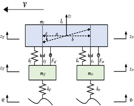
a) Constant-speed condition
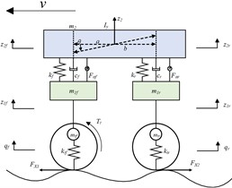
b) Launch condition
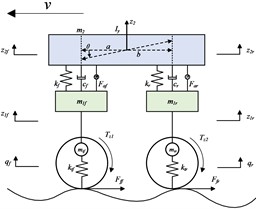
c) Emergency braking condition
Following Newton’s second law, with the front- and rear-unsprung masses as dynamic subsystems, the governing differential equations are derived:
where is the sprung mass, is the moment of inertia of the sprung mass about the -axis, and are the front and rear wheel masses, and are the front and rear suspension stiffnesses, and are the front and rear suspension damping coefficients, and are the front and rear tire stiffnesses, and are the longitudinal distances from the front and rear axles to the vehicle's center of mass.
The state variables , output variables and input variables are defined as follows:
where is the vertical displacement of the vehicle body, is the pitch angle of the vehicle body, and are the vertical displacements of the front and rear wheels, - and - are the dynamic deflections of the front and rear suspensions, and are the road excitations at the front and rear wheels, and are the active forces of the front and rear suspensions.
Transform the above equations into state-space equations, where A, B, C, D are the coefficient matrices of the state-space equations (coefficient matrices are shown in Appendix A1):
2.2.2. Launch condition
The developed 4-DOF half-car model incorporates longitudinal pitch dynamics and vertical motion kinematics. The sprung mass exhibits vertical displacement and pitch rotation, whereas the unsprung masses demonstrate vertical displacement exclusively. The front and rear suspension systems are interconnected via linear spring-damper elements, with integrated modeling of traction and braking system dynamics during startup/braking transients. This modeling framework enables accurate simulation of critical dynamic phenomena including load transfer and vehicle attitude variations during acceleration/deceleration phases. The wheelie phenomenon caused by load transfer during vehicle launch deteriorates the vehicle's posture. The dynamic force distribution analysis of the 4-DOF half-car model is schematically represented in Fig. 1.
Following Newtonian mechanics, force equilibrium analysis of the driven wheels and non-driven wheels yields distinct governing equations:
where is the rolling resistance coefficient, is the vertical load on the wheel, and is the driving force (front-wheel drive).
The governing equation for pitch-axis rotational dynamics of the vehicle’s sprung mass is formulated as follows:
Based on the 4-DOF suspension system dynamics model under constant-speed condition, the dynamic model under startup condition is rewritten as a state-space equation, with the input variables set as: (coefficient matrices are shown in Appendix A2).
2.2.3. Emergency braking condition
During emergency braking conditions, due to the acceleration provided by tire-road friction forces which result in load redistribution between the front and rear wheels, excessive vehicle pitch angle may occur. This deteriorates the vehicle's driving posture and increases braking distance.
The differential equations of vehicle motion under emergency braking conditions are as follows:
The ground support forces on the front and rear wheels under the effect of braking torque and active forces are expressed as follows:
Since the vehicle’s center of mass height is much greater than the road excitation height, the differential equation for the pitch-axis dynamics can be simplified to:
Based on the 4-DOF suspension system dynamics model under constant-speed condition, the dynamic model under emergency braking conditions is rewritten as a state-space equation, with the input variables set as: (coefficient matrices are shown in Appendix A3).
3. PSO-PPO algorithm-based active suspension control method
3.1. Integrated workflow for active suspension control
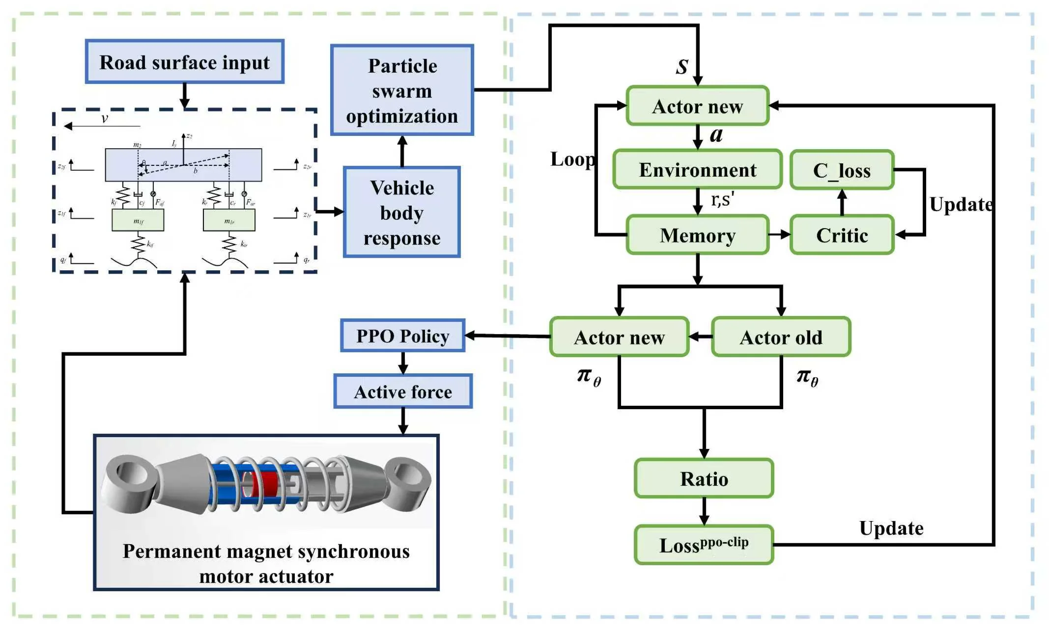
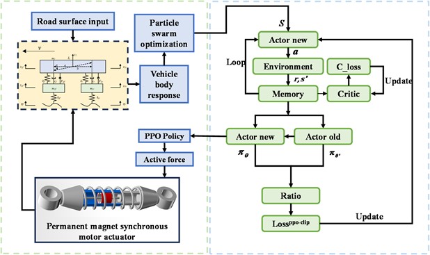
This paper combines the PSO-PPO algorithm with active suspension systems. The overall process involves sensors collecting road information input to the suspension system model, while the Particle Swarm Optimization (PSO) algorithm pre-trains with the environment to generate the optimal initial policy required for Proximal Policy Optimization (PPO) training. The agent is trained through reinforcement learning, continuously optimizing the control policy based on obtained reward values until the control performance converges. The deployed agent then selects corresponding action as outputs according to the probability density function in the Actor network. The interaction process between the PSO-PPO algorithm and the suspension environment is shown in Fig. 2.
Fig. 2PSO-PPO algorithm suspension control architecture
3.2. PSO-PPO algorithm workflow
To address the issues of instability during the initial training phase and prolonged convergence time in reinforcement learning algorithms, this paper proposes a control method that integrates the PSO algorithm and the PPO algorithm. Specifically, the PSO algorithm is employed to generate parameters for the Actor network, which are pre-evaluated through environmental interaction using the cumulative rewards of trajectories as fitness criteria. The PPO algorithm then adopts the Actor network parameters with the highest fitness as the initial policy for agent training. A multi-objective optimization framework is designed to configure key parameters of the reinforcement learning control algorithm, including the reward function, learning rate, and discount factor. The interaction logic between the PSO and PPO algorithms is illustrated in Fig. 3.
In the field of suspension control, the initial policy generated by the PSO algorithm is applied to the suspension system. The cumulative reward calculated from vehicle-body responses induced by road-vehicle interaction serves as the fitness metric, with the fitness function formulated as:
The velocity update formula governing particle position and search speed in the PSO algorithm is expressed as:
where and are random numbers uniformly distributed in the interval [0, 1], introduced to enhance the stochastic exploration capability of the algorithm. The acceleration constants and , which control the learning rates of individual and social cognition respectively, are set to 1.5. The inertia weight , governing the momentum preservation in particle motion, is assigned a value of 0.5.
Fig. 3Interaction logic between the PSO and PPO algorithms
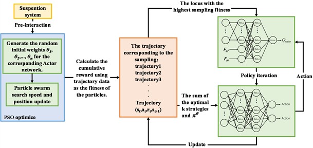
The PSO algorithm generates optimal initial policies required for subsequent reinforcement learning through preliminary interaction with the suspension environment, thereby reducing blind exploration during the initial training phase, improving sample efficiency, and accelerating convergence.
In reinforcement learning, policy gradient methods maximize expected returns by directly optimizing policy parameters. However, traditional policy gradient approaches are prone to high-variance gradient estimates, leading to unstable training. Moreover, policy updates may cause drastic fluctuations in policy performance, or even policy collapse. To address these issues, the PPO algorithm introduces a surrogate objective with clipped probability ratios, constraining policy update magnitudes. This mechanism ensures policy improvement while preventing gradient overshooting, with the clipping function formulated as:
where denotes the probability ratio between new and old policies, and controls the clipping range.
In the PPO-based suspension system control algorithm, the neural network comprises an Actor network and a Critic network, responsible for generating control actions and evaluating the current state value, respectively. Both networks share an identical architecture: an input layer followed by two hidden layers. The network architecture parameters are detailed in Table 1.
Table 1Network architecture parameters
Element | Number of neurons | Activation function |
Input layer | 1 | – |
Fully connected layer 1 | 24 | ReLU |
Fully connected layer 2 | 24 | ReLU |
Output layer | 1 | Linear |
By properly configuring these parameters, a neural network with moderate complexity can be constructed to enhance control effectiveness while maintaining efficiency and stability during training. The Actor network optimizes the parameters in the control policy through the gradient descent algorithm, directly learning action-output policies from the state space to maximize cumulative rewards. The PPO algorithm employs the Critic network to evaluate the quality of the Actor network’s policy. The core task of the Critic network is to compute the state value function , which predicts the expected cumulative rewards obtainable under the current policy when in state . The target state value function is calculated using the Generalized Advantage Estimation (GAE) method:
where is the predicted value, is the target value, is the GAE factor.
When the PPO algorithm completes a policy update, the new policy is used for subsequent iterations until policy convergence is achieved, ultimately applied to output the active force required for suspension control.
In summary, the training workflow of the PSO-PPO-based active suspension control method is as shown in Table 2.
Table 2Training workflow of the PSO-PPO-based active suspension control method
Initialize suspension parameters. Initialize road excitation seeds. Initialize particle swarm optimization (PSO) parameters: Particle positions , Velocity vectors , Velocity limits, Solution space boundaries and Population size . for 1 to do Update particle positions and velocity vectors using cumulative reward as the fitness metric: Initialize parameters of the Actor and Critic networks as and . Actor network update Initialize the Actor policy using fitness-prioritized trajectories from PSO. Generate trajectory batch and state-action pairs (, ) through policy execution in the environment. Calculate action probability density using mean and variance, then compute importance sampling ratio via logarithmic transformation: Calculate the advantage function based on the current state-value function: Apply clipped objective function to constrain policy update magnitude: Optimize policy parameters using gradient descent method: Policy updates formula can be expressed as: Critic network update Compute target state-value function using Generalized Advantage Estimation: Compute prediction-target discrepancy and minimize loss for state-value approximation, loss function as follows: Update Critic network parameters via gradient descent: End for |
3.3. PSO-PPO training parameter configuration
According to the characteristics of different road conditions and driving scenarios, the performance weighting factors are adjusted, enabling the suspension system to adapt dynamically under various road conditions to optimize both comfort and stability. This design approach reduces complexity in the reward function while ensuring that reward signals during the reinforcement learning process can effectively guide the agent's learning and optimization. To prevent excessive influence from single variables on the reward function, reward scaling is typically employed. The reward function is formulated as follows:
where , , , , and represent the weighting coefficients for body acceleration, front suspension dynamic deflection, rear suspension dynamic deflection, front tire dynamic travel, rear tire dynamic travel, and body pitch angular acceleration, respectively.
In reinforcement learning, performance requirements vary with operating conditions, while adjusting weighting coefficients enhances control effectiveness. The learning rate is a critical hyperparameter that controls the step size of parameter updates during training. When vehicle body responses exhibit significant fluctuations, increasing the learning rate can improve adaptation capability. Proper learning rate tuning substantially improves training efficiency and convergence speed. The reward weighting coefficients and learning rates for each evaluation metric under various operating conditions are provided in Table 3.
Table 3Weighting coefficients and learning rate for various metrics
Weight coefficients | Launch | Constant-speed | Emergency braking |
Body acceleration () | 10 | 1000 | 10 |
Dynamic deflection (, ) | 1000 | 1 | 1000 |
Dynamic travel (, ) | 1 | 1.5 | 1 |
Pitch angular acceleration () | 10 | 10 | 10 |
Learning rate for Actor | 0.05 | 0.005 | 0.05 |
Learning rate for Critic | 0.1 | 0.01 | 0.1 |
The configuration of hyperparameters in reinforcement learning directly impacts training efficiency and convergence rate. Key parameters in the PSO-PPO algorithm include the clipping factor, neural network parameters, entropy coefficient, and discount factor. The hyperparameter configurations are listed in Table 4.
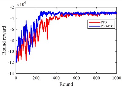
After configuring the reinforcement learning parameters, the agent training process is conducted. The training convergence curves of the baseline PPO algorithm and the PSO-PPO hybrid control method are compared in Fig. 4.
As shown, utilizing PSO for pre-training exploration to generate high-quality initial samples significantly reduces random exploration in the early training phase. This mechanism improves sample efficiency and enables accelerated policy convergence compared to standard PPO.
Table 4Training hyperparameters for proximal policy optimization algorithm
Hyperparameters | Symbols | Values |
Discount factor | 0.98 | |
Sampling time | 6 | |
Entropy loss weight | 0.04 | |
Clipping factor | 0.2 | |
GAE factor | 0.9 | |
Maximum training episodes | – | 1000 |
Training steps per iteration | – | 600 |
Fig. 4Reinforcement learning training process
3.4. Multi-condition-oriented control methodology
The PSO-PPO algorithm generates distinct control policies for three operational modes, each requiring dynamic weight allocation of suspension performance objectives. While scenario-specific reward weights are tuned for individual modes, real-world driving typically involves hybrid modes requiring real-time weight adaptation. This multi-condition suspension control problem constitutes a multi-objective optimization challenge with evaluation criteria and performance metrics, for which the entropy weighting method provides an ideal solution. The information entropy is defined as:
where is the information entropy, is the source alphabet size, specifies the occurrence probability of information unit .
The entropy weight method determines relative importance weights for multi-objective decision criteria through the following standardized steps:
3.4.1. Data matrix formalization
For a multi-criteria decision problem with evaluation objects and evaluation metrics, the standardized data matrix is constructed as follows:
The matrix undergoes standardized transformation via Eq. (24) to yield Eq. (25), formally expressed as:
where is the normalized value, .
3.4.2. Entropy calculation
For the -th evaluation criterion in a multi-criteria decision system, its information entropy is formally defined as:
3.4.3. Weight derivation
Determine weight via entropy divergence:
Using the aforementioned equations, the RMS values of each performance metric obtained under three operating conditions are assigned as matrix elements. During multi-condition driving, the primary optimization parameter is suspension dynamic deflection, followed by body acceleration and tire dynamic displacement. Accordingly, the reward function weights are set as 0.3666 for the launch condition, 0.2372 for the cruise condition, and 0.3961 for the emergency braking condition. The final reward value is calculated through weighted summation of distinct reward functions, and the trained agent for multi-condition scenarios is ultimately obtained.
By introducing a weighted reward function that adaptively adjusts weights across operating conditions according to their priority significance, the RL-based algorithm maintains performance assurance in multi-condition scenarios:
where , and represent the weight coefficients corresponding to the reward functions of three operating conditions, satisfying the relationship 1. denotes the startup condition reward function, the constant-speed condition reward function, and the emergency braking condition reward function.
4. Simulation results
The simulation experiments were conducted using MATLAB/Simulink for modeling, with three individual operating conditions employing a 4-DOF half-car model as the research subject. The parameters of the vehicle model used for the MATLAB /Simulink simulations are shown in Table 5.
Table 5The main parameters of vehicle simulation
Name | Unit | Value |
Sprung mass | kg | 600 |
Moment of inertia (-axis) | kg·m2 | 1000 |
Front/Rear unsprung mass | kg | 40 |
Front/Rear suspension stiffness | N/m | 20000 |
Front/Rear suspension damping | N·s/m | 1000 |
Front/Rear tire stiffness | N/m | 200000 |
Front/Rear axle to centroid | m | 1/1.5 |
Under multiple operating conditions, a co-simulation was conducted using CarSim and MATLAB /Simulink, with the full vehicle model in CarSim as the research subject and road surface input configured within CarSim. During the Carsim-MATLAB /Simulink co-simulation process: First, the active suspension system model was constructed in CarSim with corresponding parameters set in the software. After completing the setup, the two software platforms were connected via a custom Simulink extension solver. During simulation runtime, CarSim transmitted the state parameters of the active suspension system to Simulink. Upon receiving these data, Simulink imports them into the control module for processing and calculation to derive corresponding control quantities. Simulink then feeds the calculated control quantities back to Carsim, which subsequently processes the received active suspension force information and updates the system states. CarSim again transmitted the updated active suspension system state parameters to Simulink, thereby forming a closed-loop system.
4.1. Constant-speed condition
To verify the control effectiveness of the reinforcement-learning-based active suspension control method under constant-speed conditions, a comparative simulation analysis was conducted involving a passive suspension system, a conventional LQR-based active suspension system, and a PSO-PPO-algorithm-based active suspension system.
The comparative experiments were configured with three test scenarios:
1) Simulation experiments and result analysis of suspension systems under constant-speed driving at 20 m/s on class C roads.
2) Simulation experiments and result analysis of suspension systems under constant-speed driving at 20 m/s on class D roads.
3) Simulation experiments and result analysis of suspension systems under constant-speed driving on sequentially varying road surfaces (class A, B, C).
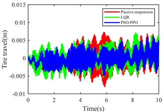
Fig. 5 shows the simulation results of body acceleration, pitch angular acceleration, front/rear suspension dynamic deflection, and front/rear tire dynamic travel when the vehicle travels at 20 m/s on class C roads.
Fig. 6 shows the simulation results of body acceleration, pitch angular acceleration, front/rear suspension dynamic deflection, and front/rear tire dynamic travel when the vehicle travels at 20 m/s on class D roads.
Tables 6 and 7 present the RMS values of various metrics for passive suspension, LQR-based active suspension, and PSO-PPO-algorithm-based active suspension under identical test conditions, along with the percentage improvement (“-“ indicates improvement; “+” indicates deterioration) of both active suspension control methods compared to passive suspension. Table 8 present the standard deviation of various metrics for 5 program runs.
Fig. 5Suspension response under class C road excitation
a) Body acceleration
b) Pitch angular acceleration
c) Front suspension dynamic deflection
d) Rear suspension dynamic deflection
e) Front tire dynamic travel
f) Rear tire dynamic travel
The PSO-PPO algorithm demonstrates superior control performance compared to both the LQR-based controller and passive suspension systems across all evaluated metrics. Under class C road conditions, the algorithm achieves 49.1 % reduction in body acceleration and 25.7 % suppression in pitch angular acceleration, while on class D roads, these improvements reach 39.1 % and 38.2 %, respectively, significantly outperforming the LQR method. This capability enables dual optimization of vehicle stability and ride comfort through effective vibration mitigation and dynamic response control. Furthermore, the algorithm exhibits outstanding suspension control performance, with front and rear suspension dynamic deflections improved by 25.4 % and 29.8 % respectively, surpassing LQR's optimization results. Although its improvement on tire dynamic travel is relatively modest, the PSO-PPO algorithm still demonstrates positive impacts on overall suspension system performance. Collectively, the PSO-PPO algorithm shows significant advantages over LQR in control precision and response stability, particularly in suppressing body acceleration and pitch angular acceleration. These capabilities enable superior control effectiveness, further enhancing the comprehensive performance of suspension systems.
Fig. 6Suspension response under class D road excitation
a) Body acceleration
b) Pitch angular acceleration
c) Front suspension dynamic deflection
d) Rear suspension dynamic deflection
e) Front tire dynamic travel
f) Rear tire dynamic travel
Table 6RMS values of various metrics
Passive suspension | LQR | PSO-PPO | ||||
C | D | C | D | C | D | |
Body acceleration (m/s2) | 0.4403 | 0.8806 | 0.3075 | 0.8213 | 0.2239 | 0.6546 |
Pitch angular acceleration (rad/s2) | 0.2763 | 0.5527 | 0.2303 | 0.4244 | 0.1681 | 0.3414 |
Front suspension deflection (m) | 0.0058 | 0.0116 | 0.0051 | 0.0112 | 0.0043 | 0.0088 |
Rear suspension deflection (m) | 0.0048 | 0.0096 | 0.0039 | 0.0085 | 0.0033 | 0.0068 |
Front tire travel (m) | 0.0160 | 0.0321 | 0.0160 | 0.0321 | 0.0152 | 0.0305 |
Rear tire travel (m) | 0.0158 | 0.0317 | 0.0158 | 0.0317 | 0.0150 | 0.0301 |
Table 7Percentage improvement of various metrics
LQR | PSO-PPO | |||
C | D | C | D | |
Body acceleration (m/s2) | –30.1 % | –6.7 % | –49.1 % | –25.7 % |
Pitch angular acceleration (rad/s2) | –16.6 % | –23.2 % | –39.1 % | –38.2 % |
Front suspension deflection (m) | –12.1 % | –4.0 % | –25.4 % | –24.2 % |
Rear suspension deflection (m) | –19.1 % | –11.5 % | –29.8 % | –29.2 % |
Front tire travel (m) | +0.0 % | +0.0 % | –5.0 % | –5.0 % |
Rear tire travel (m) | +0.1 % | +0.1 % | –4.9 % | –4.9 % |
Table 8Standard deviation of various metrics
PSO-PPO | ||
C | D | |
Body acceleration (m/s2) | 0.000924813 | 0.003467646 |
Pitch angular acceleration (rad/s2) | 0.001520187 | 0.003505851 |
Front suspension deflection (m) | 0.000020175 | 0.000090473 |
Rear suspension deflection (m) | 0.000020305 | 0.000072371 |
Front tire travel (m) | 0.000001826 | 0.000005878 |
Rear tire travel (m) | 0.000009695 | 0.000005117 |
To verify the universal adaptability of the control algorithm, a continuously varying random road excitation was configured, where the road condition transitioned sequentially from class A to class B, then to class C, and finally back to class B. Each road segment lasted 10 seconds, with a total simulation time set to 40 seconds. The variation in random road excitation levels is shown in Fig. 7.
Fig. 8. shows the body acceleration curves of the vehicle traveling at 20 m/s on time-varying road surfaces.
As evidenced in Table 9, the PSO-PPO-algorithm-based active suspension demonstrates superior performance in body acceleration reduction compared to both passive suspension and LQR-based active suspension, with explicit percentage improvements explicitly quantified in the table. The table also present the standard deviation of Body acceleration for 5 program runs. These comparative simulations confirm the algorithm's generalization capabilities across progressively changing road profiles, maintaining effective vibration suppression when handling diverse pavement classifications.
Fig. 7Stochastic road excitation classification variation
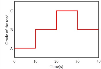
Fig. 8Body acceleration under continuously varying road excitation
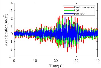
Table 9RMS and percentage improvement of various metrics
Passive | LQR | PSO-PPO | ||||
RMS | RMS | Percentage | RMS | Percentage | Std | |
Body acceleration (m/s2) | 0.5585 | 0.4127 | –26.11 % | 0.3043 | –45.5 % | 0.00811137 |
4.2. Launch condition
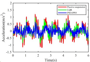
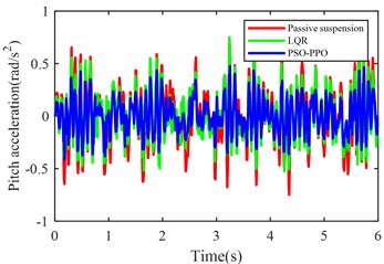
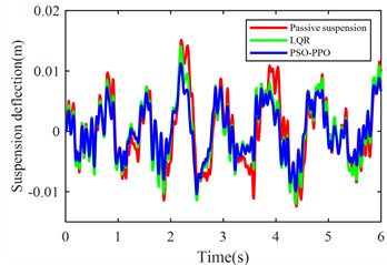
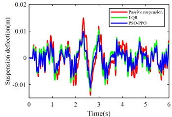
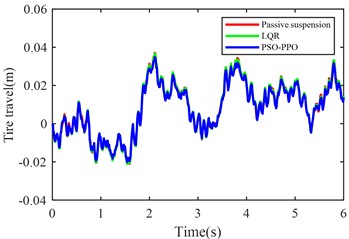
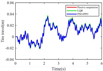
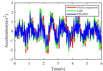
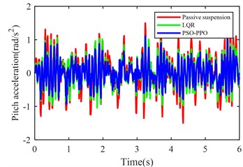
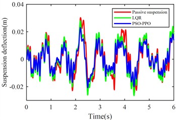
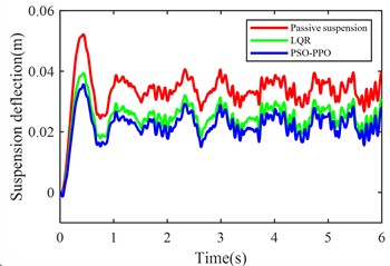
The launch condition simulation experiment was configured with the vehicle accelerating from rest on class C road under a constant driving force 2200 N, with the simulation duration set to 6 seconds. Fig. 9. displays comparative results of body acceleration, pitch angular acceleration, pitch angle variation, front/rear suspension dynamic deflections, and front/rear tire dynamic travels for passive suspension, LQR-controlled active suspension, and PSO-PPO-algorithm-controlled active suspension systems under launch conditions.
Table 10 lists the RMS values of these metrics for all three suspension configurations, with percentage improvements of both active control methods calculated relative to the passive suspension baseline. Table 11 present the standard deviation of various metrics for 5 program runs.
Fig. 9Suspension response under launch condition
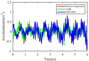
a) Body acceleration
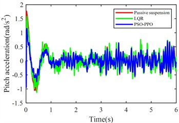
b) Pitch angular acceleration
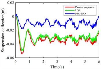
c) Front suspension dynamic deflection
d) Rear suspension dynamic deflection
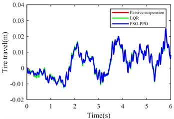
e) Front tire dynamic travel
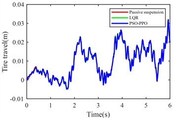
f) Rear tire dynamic travel
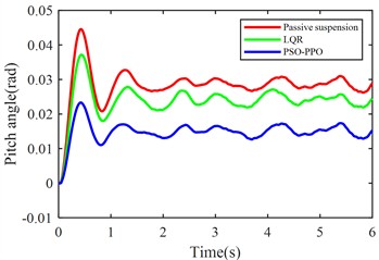
g) Pitch angle variation
Under launch conditions, the PSO-PPO-algorithm-controlled active suspension demonstrates 68.52 % optimization in front suspension dynamic deflection and 33.89 % optimization in rear suspension dynamic deflection compared to passive suspension, achieving 47.52 % reduction in vehicle body pitch angle. This enhancement in body posture stability is attained without adversely affecting other vehicle performance metrics. Additionally, the PSO-PPO-algorithm-controlled system surpasses the LQR-controlled active suspension in all performance indicators except body acceleration.
Table 10RMS values of various metrics
Passive | LQR | PSO-PPO | |||
RMS | RMS | Percentage | RMS | Percentage | |
Body acceleration (m/s2) | 0.2748 | 0.2232 | –18.78 % | 0.2722 | –0.95 % |
Pitch angular acceleration (rad/s2) | 0.3534 | 0.3391 | –4.05 % | 0.2593 | –26.63 % |
Front suspension deflection (m) | 0.0343 | 0.0312 | –9.04 % | 0.0108 | –68.52 % |
Rear suspension deflection (m) | 0.0341 | 0.0254 | –25.51 % | 0.0225 | –33.89 % |
Front tire travel (m) | 0.0085 | 0.0086 | +1.18 % | 0.0085 | –0.02 % |
Rear tire travel (m) | 0.0123 | 0.0124 | +6.91 % | 0.0124 | +0.07 % |
Vehicle pitch angle (rad) | 0.0288 | 0.0242 | –19.01 % | 0.0151 | –47.52 % |
Table 11Standard deviation of various metrics
PSO-PPO | |
Body acceleration (m/s2) | 0.001800083 |
Pitch angular acceleration (rad/s2) | 0.002636746 |
Front suspension deflection (m) | 0.000032011 |
Rear suspension deflection (m) | 0.000050072 |
Front tire travel (m) | 0.000003895 |
Rear tire travel (m) | 0.000004238 |
Vehicle pitch angle (rad) | 0.000062524 |
4.3. Emergency braking condition
Emergency braking condition simulation experiments were configured as follows:
1) Passive suspension vehicle (without ABS system) braking from 20 m/s to full stop with maximum braking force on class C roads.
2) Passive suspension vehicle (with ABS system) braking from 20 m/s to full stop with maximum braking force on class C roads.
3) Active suspension vehicle (with ABS system) braking from 20 m/s to full stop with maximum braking force on class C roads.
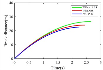
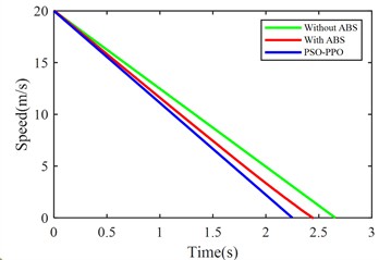
Fig. 10 compares suspension pitch angle, body acceleration, braking distance, vehicle speed, front/rear suspension dynamic deflection, and front/rear tire dynamic travel across the three control methods under emergency braking.
Table 12 quantifies RMS values of vehicle performance metrics for each control strategy. Table 13 presents the comparative analysis of braking distance and braking time across these control configurations. Table 14 details percentage improvement comparisons among control strategies. Table 15 present the standard deviation of various metrics for 5 program runs.
Table 12RMS values of various metrics under different control strategies
Without ABS | With ABS | PSO-PPO | |
Body acceleration (m/s2) | 0.4408 | 0.3467 | 0.6258 |
Vehicle pitch angle (rad) | 0.0573 | 0.0618 | 0.0315 |
Front suspension deflection (m) | 0.0686 | 0.0726 | 0.0565 |
Rear suspension deflection (m) | 0.0675 | 0.0739 | 0.0569 |
Front tire travel (m) | 0.0116 | 0.0089 | 0.0137 |
Rear tire travel (m) | 0.0103 | 0.0119 | 0.0085 |
Table 13Braking distance and braking time under different control strategies
Without ABS | With ABS | PSO-PPO | |
Braking distance (m) | 26.5826 | 24.0042 | 22.6392 |
Braking time (s) | 2.6561 | 2.4420 | 2.2497 |
Fig. 10Suspension response under emergency braking condition
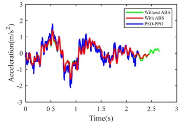
a) Body acceleration
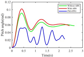
b) Pitch angle variation
c) Break distance
d) Speed
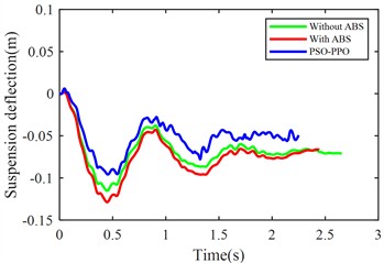
e) Front suspension dynamic deflection
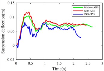
f) Rear suspension dynamic deflection
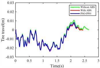
g) Front tire dynamic travel
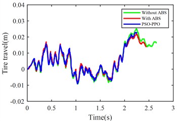
h) Rear tire dynamic travel
From the perspective of braking performance, the ABS demonstrates 9.7 % reduction in braking distance and 8.06 % decrease in braking duration compared to non-ABS configurations, enhancing stopping efficiency. The PSO-PPO-algorithm-controlled active suspension further refines these parameters, achieving 14.83 % shorter braking distance and 15.29 % reduced braking time, establishing itself as the superior configuration.
From the perspective of body stability, although ABS improves braking performance, it increases body pitch angle by 7.86 %, and front/rear suspension dynamic deflections by 5.82 % and 9.52 % respectively, indicating compromised posture control. In contrast, the PSO-PPO-algorithm-controlled active suspension reduces pitch angle by 45.06 %, and decreases the front/rear suspension dynamic deflections by 17.63 % and 15.8 %, significantly enhancing stability during braking.
Table 14Percentage improvement of various metrics under different control strategies
With ABS | PSO-PPO | |
Braking distance (m) | –9.70 % | –14.83 % |
Body acceleration (m/s2) | –21.34 % | +41.98 % |
Vehicle pitch angle (rad) | +7.86 % | –45.06 % |
Front suspension deflection (m) | +5.82 % | –17.63 % |
Rear suspension deflection (m) | +9.52 % | –15.80 % |
Front tire travel (m) | –23.97 % | +17.78 % |
Rear tire travel (m) | +16.08 % | –17.25 % |
Table 15Standard deviation of various metrics
PSO-PPO | |
Body acceleration (m/s2) | 0.018990738 |
Vehicle pitch angle (rad) | 0.000354325 |
Front suspension deflection (m) | 0.000194675 |
Rear suspension deflection (m) | 0.000954778 |
Front tire travel (m) | 0.000007383 |
Rear tire travel (m) | 0.000009367 |
Braking distance (m) | 0.05882 |
Braking time (s) | 0.03545 |
From the perspective of suspension dynamic performance, ABS reduces front-wheel dynamic travel by 23.97 % but increases rear-wheel dynamic travel by 16.08 %, revealing front/rear response imbalance. The PSO-PPO-algorithm-controlled active suspension increases front-wheel dynamic travel by 17.78 % and reduces rear-wheel dynamic travel by 17.25 %, improving wheel motion balance. It increases vertical body acceleration by 41.98 %, potentially affecting ride comfort and necessitating control strategy optimization.
In summary, the PSO-PPO-algorithm-controlled active suspension improves braking performance and body attitude control, reducing vehicle pitch motion and tire dynamic deflection. This 9.70 % braking distance improvement is achieved at the cost of ride comfort degradation, with vertical body acceleration RMS value worsening by 41.98 %.
4.4. Multi-operating condition
The active suspension multi-condition co-simulation experimental setup was configured in CarSim with three sequential phases: From 0-3 seconds, the vehicle accelerated from 0 to 20 m/s; subsequently maintained a constant speed of 20 m/s until the 8th second; and finally executed emergency braking from 8-10 seconds, completing the total 10-second simulation duration.
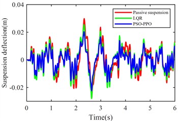
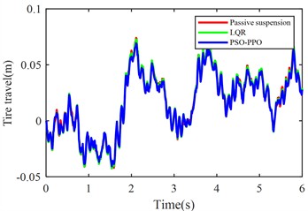
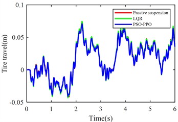
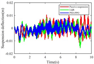
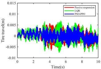
Fig. 11 compares body vertical acceleration, pitch angular acceleration, front-left/rear-left suspension dynamic deflections, front-right/rear-right suspension dynamic deflections, front-left/rear-left tire dynamic travel, and front-right/rear-right tire dynamic travel across passive suspension, LQR-controlled active suspension, and PSO-PPO-algorithm-controlled active suspension under multi-condition operations.
Table 16 quantifies RMS values of performance metrics for all three configurations (passive, LQR-controlled, PSO-PPO-algorithm-controlled), including percentage improvements of active control methods relative to the passive suspension baseline. Table 17 present the standard deviation of various metrics for 5 program runs.
Fig. 11Suspension response under multiple operating conditions
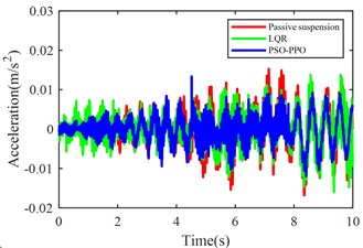
a) Body acceleration
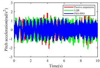
b) Pitch angular acceleration
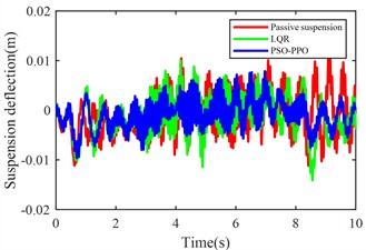
c) Front-left suspension dynamic deflection
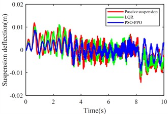
d) Rear-left suspension dynamic deflection
e) Front-right suspension dynamic deflection
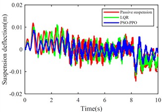
f) Rear-right suspension dynamic deflection
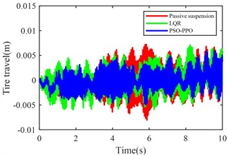
g) Front-left tire dynamic travel
h) Rear-left tire dynamic travel
i) Front-right tire dynamic travel

j) Rear-right tire dynamic travel
The multi-condition co-simulation experimental results demonstrate that the PSO-PPO-algorithm-controlled active suspension system achieves comprehensive performance superiority over the LQR-controlled counterpart. The PSO-PPO algorithm achieves a 29.92 % reduction in vertical body acceleration, outperforming the LQR controller’s 17.65 % improvement. In evaluations of suspension dynamic deflection reflecting system stability, the PSO-PPO algorithm delivers 26.19 %-34.09 % optimization, significantly exceeding the LQR controller’s narrow 4.55 %-7.14 % enhancement range. Regarding tire dynamic travel critical for roadholding safety, the PSO-PPO achieves 17.39 %-28.57 % improvements across all wheel stations, while LQR controller exhibits 8.7 % performance deterioration at rear wheel stations, revealing inherent limitations in multi-objective coordinated control scenarios.
Table 16RMS values of various metrics
Passive | LQR | PSO-PPO | |||
RMS | RMS | Percentage | RMS | Percentage | |
Body acceleration (m/s2) | 0.0051 | 0.0042 | –17.65 % | 0.0036 | –29.92 % |
Pitch angular acceleration (rad/s2) | 0.6518 | 0.7479 | +14.74 % | 0.6963 | +6.83 % |
Front-left suspension deflection (m) | 0.0042 | 0.0039 | –7.14 % | 0.0031 | –26.19 % |
Rear-left suspension deflection (m) | 0.0044 | 0.0042 | –4.55 % | 0.0029 | –34.09 % |
Front-right suspension deflection (m) | 0.0043 | 0.0040 | –6.98 % | 0.0031 | –27.78 % |
Rear-right suspension deflection (m) | 0.0044 | 0.0042 | –4.55 % | 0.0029 | –32.87 % |
Front-left tire travel (m) | 0.0027 | 0.0025 | –7.41 % | 0.0020 | –25.93 % |
Rear-left tire travel (m) | 0.0023 | 0.0025 | +8.70 % | 0.0019 | –17.39 % |
Front-right tire travel (m) | 0.0028 | 0.0025 | –10.71 % | 0.0020 | –28.57 % |
Rear-right tire travel (m) | 0.0023 | 0.0025 | +8.70 % | 0.0019 | –17.39 % |
Table 17Standard deviation of various metrics
PSO-PPO | |
Body acceleration (m/s2) | 0.00085206794 |
Pitch angular acceleration (rad/s2) | 0.07487705523 |
Front-left suspension deflection (m) | 0.00026228864 |
Rear-left suspension deflection (m) | 0.00101151904 |
Front-right suspension deflection (m) | 0.00043985011 |
Rear-right suspension deflection (m) | 0.00060324768 |
Front-left tire travel (m) | 0.00045632466 |
Rear-left tire travel (m) | 0.00111302064 |
Front-right tire travel (m) | 0.00090736396 |
Rear-right tire travel (m) | 0.00116305784 |
5. Conclusions
To address the poor generalization performance and extended training cycles of reinforcement learning-based active suspension control systems, this study proposes a multi-condition-oriented PSO-PPO reinforcement learning control method for active suspension. By integrating the PSO algorithm with the PPO algorithm, the training efficiency of reinforcement learning is enhanced, and the effectiveness and generalization capability of the proposed method are validated through agent training across diverse operating conditions.
The adoption of PSO for environmental pre-interaction significantly reduces the time spent on blind exploration during the initial training phase, improving algorithmic training efficiency. Specifically, the agent training convergence is accelerated, shortening the required episodes from 500 to 300, thereby achieving faster convergence.
In terms of performance improvements, under constant-speed conditions, the vehicle body acceleration is reduced by 49.1 %, and the pitch angular acceleration is reduced by 39.1 %. During launch conditions, the suspension dynamic deflection decreases by 68.52 %, while under emergency braking conditions, the stopping distance is reduced by 3.9434 meters.
Furthermore, in multi-condition scenarios, the PSO-PPO algorithm demonstrates comprehensive superiority over the LQR method in active control of vehicle suspension systems. Specifically, the vehicle body acceleration is reduced by 29.92 %, and the suspension dynamic deflection is reduced by 34.09 %.
References
-
D. Tan, C. Lu, and X. Zhang, “Dual-loop PID control with PSO algorithm for the active suspension of the electric vehicle driven by in-wheel motor,” Journal of Vibroengineering, Vol. 18, No. 6, pp. 3915–3929, Sep. 2016, https://doi.org/10.21595/jve.2016.16689
-
S. Palanisamy and S. Karuppan, “Fuzzy control of active suspension system,” Journal of Vibroengineering, Vol. 18, No. 5, pp. 3197–3204, Aug. 2016, https://doi.org/10.21595/jve.2016.16699
-
J. Yao, J. Q. Zhang, M. M. Zhao, and X. Li, “Active control of a nonlinear suspension with output constraints and variable-adaptive-law control,” Journal of Vibroengineering, Vol. 20, No. 7, pp. 2690–2704, Nov. 2018, https://doi.org/10.21595/jve.2018.19005
-
Q. Zhao and B. Zhu, “Multi-objective optimization of active suspension predictive control based on improved PSO algorithm,” Journal of Vibroengineering, Vol. 21, No. 5, pp. 1388–1404, Aug. 2019, https://doi.org/10.21595/jve.2018.19580
-
M. Du, D. Zhao, B. Yang, and L. Wang, “Terminal sliding mode control for full vehicle active suspension systems,” Journal of Mechanical Science and Technology, Vol. 32, No. 6, pp. 2851–2866, Jun. 2018, https://doi.org/10.1007/s12206-018-0541-x
-
D. Rodriguez-Guevara, A. Favela-Contreras, F. Beltran-Carbajal, D. Sotelo, and C. Sotelo, “Active suspension control using an MPC-LQR-LPV controller with attraction sets and quadratic stability conditions,” Mathematics, Vol. 9, No. 20, p. 2533, Oct. 2021, https://doi.org/10.3390/math9202533
-
G. Veselov and A. Sinicyn, “Synthesis of sliding control system for automotive suspension under kinematic constraints,” Journal of Vibroengineering, Vol. 23, No. 6, pp. 1446–1455, Sep. 2021, https://doi.org/10.21595/jve.2021.22083
-
I. Ahmad, X. Ge, and Q.-L. Han, “Decentralized dynamic event-triggered communication and active suspension control of in-wheel motor driven electric vehicles with dynamic damping,” IEEE/CAA Journal of Automatica Sinica, Vol. 8, No. 5, pp. 971–986, May 2021, https://doi.org/10.1109/jas.2021.1003967
-
A. Azizi and H. Mobki, “Applied mechatronics: designing a sliding mode controller for active suspension system,” Complexity, Vol. 2021, No. 1, p. 66268, May 2021, https://doi.org/10.1155/2021/6626842
-
M. Papadimitrakis and A. Alexandridis, “Active vehicle suspension control using road preview model predictive control and radial basis function networks,” Applied Soft Computing, Vol. 120, p. 108646, May 2022, https://doi.org/10.1016/j.asoc.2022.108646
-
U. K. Aminu, M. B. Muazu, T. H. Sikiru, O. C. Alioke, and J. A. Obari, “Active suspension control system using H-infinity mixed sensitivity technique with automatic weights selection,” ATBU Journal of Science, Technology and Education, Vol. 10, No. 2, pp. 1–21, 2022.
-
Y. Jeong, Y. Sohn, S. Chang, and S. Yim, “Coordinated compensation between active and semi-active actuators for suspension control system,” IEEE Access, Vol. 10, pp. 56207–56217, Jan. 2022, https://doi.org/10.1109/access.2022.3178135
-
Y. Yin, B. Luo, H. Ren, Q. Fang, and C. Zhang, “Robust control design for active suspension system with uncertain dynamics and actuator time delay,” Journal of Mechanical Science and Technology, Vol. 36, No. 12, pp. 6319–6327, Dec. 2022, https://doi.org/10.1007/s12206-022-1143-1
-
J. Joshua Robert, P. Senthil Kumar, S. Tushar Nair, D. H. Sharne Moni, and B. Swarneswar, “Fuzzy control of active suspension system based on quarter car model,” Materials Today: Proceedings, Vol. 66, pp. 902–908, Jan. 2022, https://doi.org/10.1016/j.matpr.2022.04.575
-
Y. Nan, S. Shao, C. Ren, K. Wu, Y. Cheng, and P. Zhou, “Simulation and experimental research on active suspension system with time-delay feedback control,” IEEE Access, Vol. 11, pp. 88498–88510, Jan. 2023, https://doi.org/10.1109/access.2023.3305265
-
P. K. Wong, W. Li, X. Ma, Z. Yang, X. Wang, and J. Zhao, “Adaptive event-triggered dynamic output feedback control for nonlinear active suspension systems based on interval type-2 fuzzy method,” Mechanical Systems and Signal Processing, Vol. 212, p. 111280, Apr. 2024, https://doi.org/10.1016/j.ymssp.2024.111280
-
J. Zou and X. Zuo, “Active suspension LQR control based on modified differential evolutionary algorithm optimization,” Journal of Vibroengineering, Vol. 26, No. 5, pp. 1150–1165, Aug. 2024, https://doi.org/10.21595/jve.2024.23953
-
Y. Alqudsi, F. C. Bolat, and M. Makaraci, “Optimal and robust control methodologies for 4DOF active suspension systems: A comparative study with uncertainty considerations,” Optimal Control Applications and Methods, Vol. 46, No. 1, pp. 3–27, Jul. 2024, https://doi.org/10.1002/oca.3192
-
M. J. Mahmoodabadi, N. Nejadkourki, and M. Y. Ibrahim, “Optimal fuzzy robust state feedback control for a five DOF active suspension system,” Results in Control and Optimization, Vol. 17, p. 100504, Dec. 2024, https://doi.org/10.1016/j.rico.2024.100504
-
Wu X. J., Zou L., Zhang M. H., Jiang H. H., Liu W. D., and Hu J. Q., “Sliding mode adaptive active suspension control combined with particle filter state observation,” (in Chinese), Journal of Hunan University (Natural Sciences), Vol. 51, No. 12, pp. 19–29, 2024, https://doi.org/10.16339/j.cnki.hdxbzkb.2024247
-
M. S. Ismail, J. Purbolaksono, N. Muhammad, A. Andriyana, and H. L. Liew, “Statistical analysis of imperfection effect on cylindrical buckling response,” in IOP Conference Series: Materials Science and Engineering, Vol. 100, p. 012003, Dec. 2015, https://doi.org/10.1088/1757-899x/100/1/012003
-
M. A. Mat Norman, M. R. Mohd Razean, M. H. Mohd Rosaidi, M. S. Ismail, and J. Mahmud, “Effect of fibre volume on the natural frequencies of laminated composite plate,” Materials Today: Proceedings, Vol. 75, pp. 133–139, Jan. 2023, https://doi.org/10.1016/j.matpr.2022.10.245
-
G. Liang, T. Zhao, and Y. Wei, “DDPG based self-learning active and model-constrained semi-active suspension control,” in 5th CAA International Conference on Vehicular Control and Intelligence (CVCI), pp. 1–6, Oct. 2021, https://doi.org/10.1109/cvci54083.2021.9661158
-
X. Zhu, Z. Chen, S. Zhang, and C. Zhang, “Intelligent control strategy of vehicle active suspension based on deep reinforcement learning,” in China Automation Congress (CAC), pp. 4871–4876, Nov. 2022, https://doi.org/10.1109/cac57257.2022.10054782
-
S.-Y. Han and T. Liang, “Reinforcement-learning-based vibration control for a vehicle semi-active suspension system via the PPO approach,” Applied Sciences, Vol. 12, No. 6, p. 3078, Mar. 2022, https://doi.org/10.3390/app12063078
-
Y. Wang, C. Wang, S. Zhao, and K. Guo, “Research on deep reinforcement learning control algorithm for active suspension considering uncertain time delay,” Sensors, Vol. 23, No. 18, p. 7827, Sep. 2023, https://doi.org/10.3390/s23187827
-
S. R. Kim, C. Kim, S. Shin, and S.-W. Kim, “Deep reinforcement learning for semi-active suspension: a feasibility study,” in 2023 International Conference on Electronics, Information, and Communication (ICEIC), pp. 1–5, Feb. 2023, https://doi.org/10.1109/iceic57457.2023.10049850
-
G. Wang, J. Deng, T. Zhou, and S. Liu, “Reinforcement learning-based vibration control for half-car active suspension considering unknown dynamics and preset convergence rate,” Processes, Vol. 12, No. 8, p. 1591, Jul. 2024, https://doi.org/10.3390/pr12081591
About this article

This research was funded by the Science and Technology Research Project of Chongqing Municipal Education Commission (KJQN202004009).
The datasets generated during and/or analyzed during the current study are available from the corresponding author on reasonable request.
Wei Tan: conceptualization, methodology, project administration and writing-review and editing. Guoqing Zeng: software and writing-original draft preparation. Xiankun Wei: investigation and funding acquisition. Ke Ma: software, supervision and writing-review and editing. Qi Cao: visualization and methodology. All authors have read and agreed to the published version of the manuscript.
The authors declare that they have no conflict of interest.
