Abstract
In recent years, heavy-haul railways have become a critical direction for freight transport in China, with wheel flats in wheelsets posing significant threats to operational safety and infrastructure integrity. Traditional detection methods (e.g., manual inspection, TPDS) suffer from low efficiency or limited accuracy in characterizing flat features. To address this, this study develops a rigid-flexible coupling dynamic model for C80 wagons with K6 bogies, uniquely integrated with field data from the Truck Operation Detection System (TODS) to bridge simulation and engineering application gaps. Focusing on wheel-rail force responses under wheel flat conditions, we establish a quantitative mapping relationship between flat length, vehicle speed, and impact force through polynomial fitting of simulation data (10-80 km/h for empty/loaded vehicles). To validate feasibility, a 56-channel wayside monitoring system (TODS) is installed on a heavy-haul railway, calibrated via hydraulic loading to ensure measurement accuracy. Field tests (80,541 vehicles monitored) confirm that TODS can infer flat length from detected impact forces, with results consistent with TPDS alarms but offering finer characterization of flat dimensions. This work provides a practical solution for real-time wheel flat detection, enhancing maintenance efficiency and safety in heavy-haul operations.
Highlights
- A physics-based model establishes a quantitative link between wheel flat length, vehicle speed/load, and measured wheel-rail impact force.
- A calibrated 56-channel wayside system (TODS) reliably detects impact forces, enabling inference of flat length for targeted maintenance alerts.
- Field validation (80,541 vehicles) shows TODS provides finer fault characterization than TPDS, aligning alarms and adding quantitative severity assessment.
1. Introduction
Chinese railways are currently undergoing a period of significant development, with high-speed passenger transport and heavy freight emerging as the dominant themes in railway transportation [1]. Heavy-haul railway transport, characterized by its large volume, low cost, and high economic benefits, has become an increasingly important mode of transportation, witnessing rapid global expansion [2]. The construction and development of China's heavy-haul railways began in the 1980s. Despite a relatively late start compared to other countries, the development has been swift, with over 5,000 kM of heavy-haul railways in operation by the end of 2022. Given the extensive operational mileage, continuous monitoring of vehicle conditions, including the identification of wheel tread damage and over-biased loads, is imperative for ensuring operational safety and efficiency [3].
Wheelsets, as fundamental components of rail vehicles, play a critical role in load transmission, guidance, and safety. Defects such as tread flats, spalling, and abnormal wear not only compromise operational stability but also generate excessive dynamic loads that can accelerate track degradation and elevate maintenance costs [4-6]. Traditional maintenance strategies, especially in regions like China, still rely heavily on time-based inspections and periodic overhauls, which often fail to detect early-stage damage and can lead to inefficient use of resources [7-9]. Manual inspection methods are labour-intensive and subject to human error, introducing risks of undetected faults that may evolve into critical failures.
In response to these limitations, recent years have witnessed increasing adoption of intelligent monitoring technologies and wayside detection systems that enable real-time health assessment of running vehicles [10-11]. Notably, the Train Operation Detection System (TODS) integrates track-mounted sensors to capture wheel-rail interaction forces, providing a foundation for fault detection based on impact responses [12-15]. However, most existing systems merely detect the presence of impact anomalies without the ability to quantify fault severity or link dynamic signatures to specific defect dimensions, such as wheel flat length or depth.
To overcome these limitations, this study introduces a novel integration of a physics-based dynamic model with measured TODS signals to realize quantitative fault identification. A rigid-flexible coupling multibody dynamic model of a heavy-haul freight wagon is developed using SIMPACK, incorporating nonlinear suspension characteristics, elastic deformation of wheels and rails, and dynamic boundary excitations informed by roadside detection input [16-18]. Through systematic simulations across varying speeds and flat dimensions, a mapping relationship is established between wheel flats and peak wheel-rail impact forces [19-21]. This mapping enables the conversion of raw force data into fault-specific indicators, allowing for graded warning levels and predictive threshold setting in accordance with maintenance regulations. Such an approach elevates traditional threshold-based fault alarms to a mechanism-driven diagnostic system that is both interpretable and scalable.
The reliability and feasibility of the proposed system are validated through extensive analysis of field-measured data. The results demonstrate the system's effectiveness in real-time fault monitoring, timely fault warning, and alarm functions, thereby guiding on-site maintenance operations and significantly improving the safety and economic efficiency of railway transportation. The main contributions of this study include:
(1) The establishment of a comprehensive rigid-flexible coupling dynamic model for freight vehicles, which comprehensively incorporates both the rigid and flexible characteristics of the vehicles. This model enables accurate simulation of the dynamic interactions between the wheelset and track, particularly under the demanding conditions of heavy-haul railway transportation and provides precise predictions of the wheelset state.
(2) An in-depth investigation of the dynamic response of wheel-rail forces under wheel flat conditions, revealing the mapping relationship between wheel flats and wheel-rail forces. This relationship offers a theoretical basis for wheelset fault identification, aiding engineers in understanding fault phenomena such as wheelset wear and deformation and their impact on wheel-rail forces, thereby informing the development of more effective detection and warning strategies.
(3) Optimisation of sensor layout and data acquisition schemes to ensure the accuracy and reliability of measurement data. The proposed method has demonstrated strong performance in practical applications, offering a feasible technical pathway for future large-scale deployment and application.
(4) Validation of the model and method's effectiveness and reliability through extensive analysis of field-measured data. The analysis confirms that the proposed system can accurately identify wheelset faults and issue real-time early warning signals. Further optimization of the system's performance and stability has been achieved through the in-depth analysis of these data.
2. The coupling dynamic model of wheelset and track
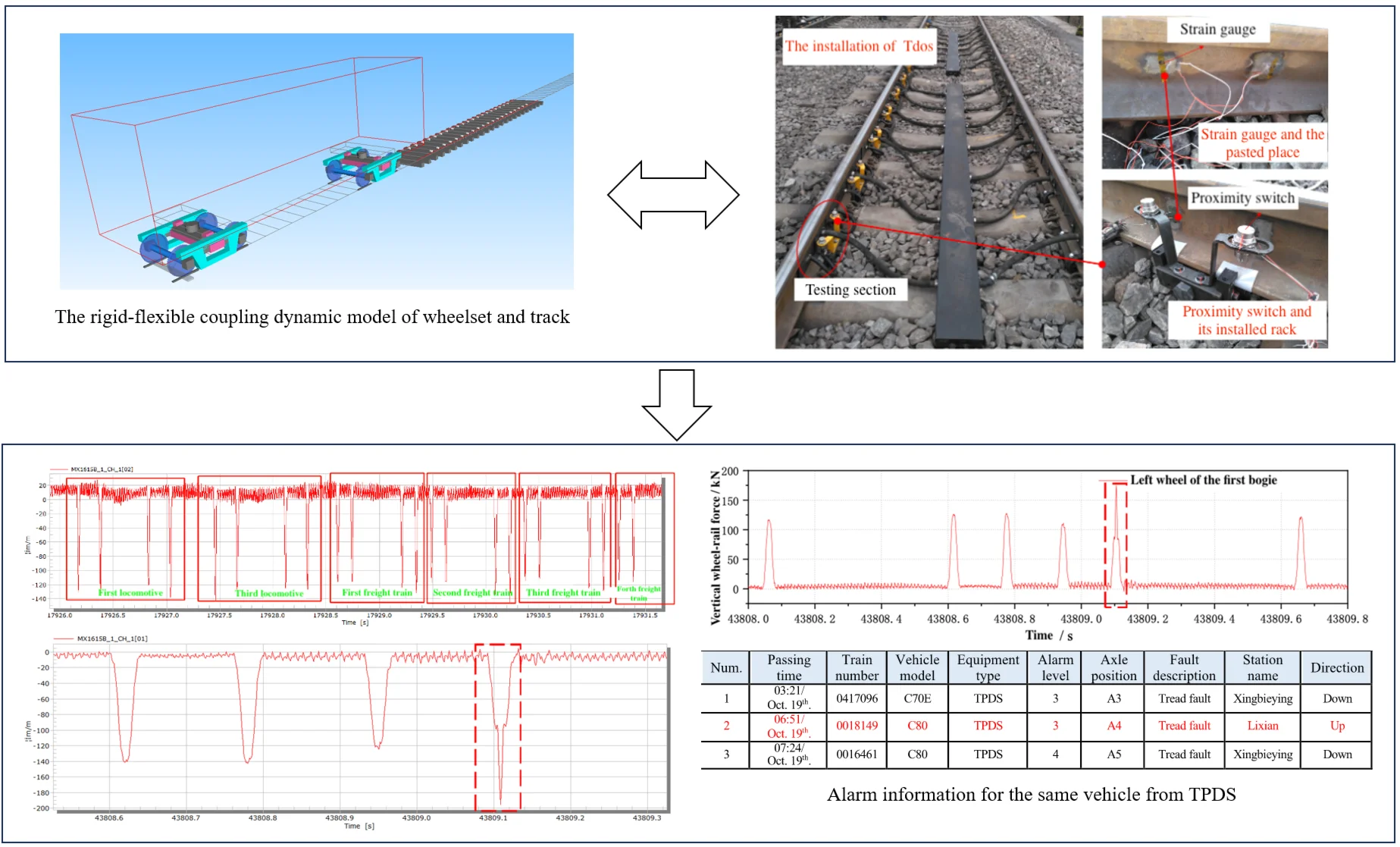
For a dedicated heavy-haul railway line utilized for coal transportation in China, a detailed finite element model of the wheelset and rail has been developed for the freight vehicle. The model is based on the C80 wagon, which features a K6 bogie and an axle load capacity of 25 tons. The C80 freight wagon, equipped with ZK6 bogies, utilises unpowered wheelsets on the wagons, while traction is provided by the locomotive. The Timoshenko beam theory is employed to accurately capture the elastic vibrations of both the wheelset and the track, addressing the shear deformation and rotary inertia effects that are critical in such systems. Additionally, the model includes various non-linear components inherent to the freight bogies, such as dry friction dampers and constant contact elastic bearings. These elements are essential for simulating the complex dynamic behavior of the vehicle under operational conditions. The integration of these non-linear characteristics results in the development of a comprehensive model featuring a flexible wheelset-track coupling dynamic system. The model is constructed using SIMPACK, a widely recognized multibody simulation software, as shown in Fig. 1.
Fig. 1The rigid-flexible coupling dynamic model of wheelset and track
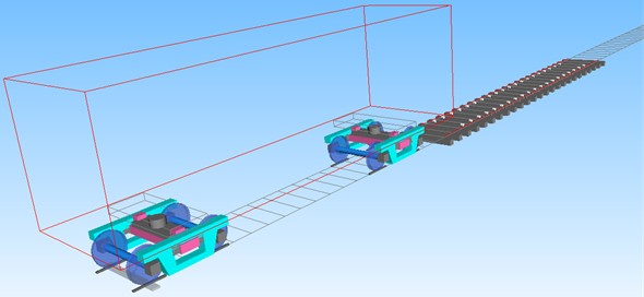
The developed model provides precise analysis of the dynamic interactions between the wheelset and rail, particularly in heavy-haul operations. Accounting for non-linearities in the bogie components is important for capturing the complex and realistic responses of the system, especially under the rigorous conditions of heavy haul transportation. The development of this model represents a significant advancement in the simulation and analysis of heavy-haul freight vehicles, providing insights that can be applied to improve vehicle performance, optimize track maintenance, and enhance overall operational safety.
3. The mapping relationship between wheel flat and wheel-rail force
Damage to the wheel tread significantly compromises the wheel-rail contact behaviour, with wheel-rail force serving as a crucial detection parameter that directly indicates the severity of tread damage. Wheel flats represent one of the most common types of tread injuries in railway vehicles, typically resulting from inadequate wheel-rail adhesion and excessive braking forces, which lead to wheel slippage and skidding. As the wheel rotates, the presence of a flat section induces periodic impacts on the rail. In extreme cases, the resulting impact forces can reach magnitudes 10 to 20 times greater than normal wheel-rail forces. Such impacts generate P1 and P2 forces [2-4], which contribute to abnormal rail vibrations. Moreover, the impact load significantly increases axle stress, with the equivalent stress at critical sections potentially doubling under these conditions, thus elevating the risk of axle fractures and introducing substantial safety hazards in train operations [5].
The relationship between wheel flats and wheel-rail forces warrants detailed examination, particularly the mapping of these variables. Historical studies have laid the groundwork for understanding this relationship, beginning in 1952 when the American Railroad Association conducted experiments on freight vehicles equipped with wheel flats operating at various speeds, thereby establishing a correlation between speed and the impact force generated by wheel flats. Subsequent research by Fermér and Nielsen [6] employed accelerometers and strain gauges to measure the track vibrations and impact forces caused by vehicles with tread damage passing over railway lines. Further advancements by Dukkipati and Dong [7] involved the development of a vehicle-track coupling model to analyse variations in wheel flat impact across different parameters.
In practice, the measurement of wheel-rail force typically involves the use of speed sensors positioned along the track to ascertain the vehicle's running speed. To achieve an effective balance between computational efficiency and the accuracy required in fitting curves for engineering applications, a two-step fitting process is applied. Initially, fitting curves are derived for the wheel-rail force as a function of the wheel flat length. Subsequently, the coefficients of the fitting function are calibrated in relation to the vehicle's operating speed. The result is a comprehensive fitting function that encapsulates the relationship between wheel-rail force, wheel flat length, and vehicle speed.
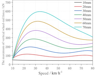
Simulation analysis is conducted for both empty and fully loaded vehicles with a wheel flat on the first wheel of the front bogie. The wheel flat has a length of 70 mm, and the simulations covered a speed range of 10 to 80 km/h. Given the need to balance simulation accuracy with the limitations of computational resources in engineering practice, the dynamic responses of both empty and fully loaded vehicles were modelled using fifth-order polynomials. The resulting fitting curves, depicted in Fig. 2, demonstrate that the polynomial approximation effectively captures the relationship between wheel-rail impact force and vehicle speed. The fitting accuracy is confirmed by the fact that the wheel-rail impact forces for randomly selected points, for both empty and loaded vehicles, fall within a 5 % error margin.
Fig. 2The fitting curves of the wheel-rail force of heavy load vehicle at wheel flat length is 70 mm
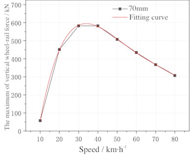
a) Empty load vehicle
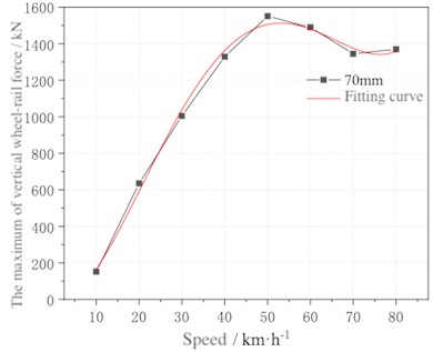
b) Heavy load vehicle
To further analyse the impact forces across different vehicle speeds, the same approach is applied to derive a fourth-order polynomial curve, as illustrated in Fig. 3. This higher-order polynomial fitting provides a robust approximation of the wheel-rail impact forces under varying operational conditions. By capturing the nonlinear behaviour of the system, particularly at higher speeds where dynamic effects become more pronounced, the polynomial model offers a more precise estimation of impact forces.
A wheel flat introduces a local loss of radius. As the flat enters the contact patch, local support reduces and the wheel–rail pair approaches a brief unloading. Re-entry of the intact tread produces a transient impact pulse. For a given flat length, higher speed leads to a larger impact because the approach and restitution occur over a shorter time. For a given speed, a longer flat deepens the loss of support and lengthens the free-rolling interval, which raises the subsequent impact. Loaded wagons carry a greater static preload and lower effective compliance, so forces are higher across the range and show stronger sensitivity to speed than empty wagons.
Fig. 4 presents the contour map of the fitting curves for both empty and fully loaded vehicles across a speed range of 10 to 80 km/h. The analysis reveals distinct trends in wheel-rail force behaviour based on the length of the wheel flat and the vehicle's load condition. For empty vehicles, when the wheel flat length is less than 60 mm, the wheel-rail force initially increases with speed, reaching a peak before subsequently decreasing as speed continues to rise. This non-linear relationship suggests that at lower flat lengths, dynamic interactions between the wheel and rail may undergo a transition, possibly due to changes in resonance conditions or the contact geometry as speed varies. However, when the wheel flat length exceeds 60 mm, the wheel-rail force consistently increases with vehicle speed. It indicates a more pronounced impact effect as the flat area becomes large enough to significantly disrupt the wheel-rail contact dynamics. In the case of fully loaded vehicles, the wheel-rail force exhibits a more straightforward relationship, with the maximum force consistently increasing as vehicle speed rises, regardless of the flat length. The added mass of the loaded vehicle likely amplifies the impact forces generated by the wheel flat, particularly at higher speeds, where kinetic energy contributes to more substantial dynamic loads on the rail. The contour map provides a valuable tool for interpreting the results from the wayside detection system. By analysing the detected wheel-rail impact force in conjunction with the vehicle's speed, it is possible to directly determine the specific length of the wheel flat. This capability facilitates the online detection and monitoring of wheel flat characteristics, enabling more effective and timely maintenance interventions.
Fig. 3Fitted wheel–rail impact force as a function of speed for multiple wheel-flat lengths
a) Empty load vehicle
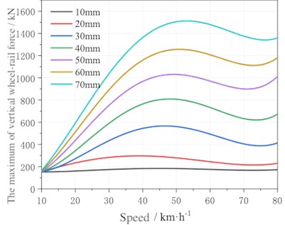
b) Heavy load vehicle
Fig. 4The contour map of fitting curve
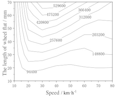
a) Empty load vehicle
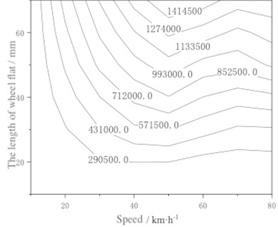
b) Heavy load vehicle
According to the Depot Repair Regulations of Railway Freight Vehicles [8], the permissible limits for wheel tread wear and damage are strictly defined to ensure safe operation. The circumferential wear depth of the repaired wheel tread must not exceed 5 mm. Additionally, the depth of scratches and local dents on the wheel tread is limited to a maximum of 0.2 mm, which are listed in Table 1, are critical for maintaining the structural integrity and safety of the wheelsets during operation. Compliance with these limits is essential to prevent excessive wear, reduce the risk of operational failures, and extend the service life of the wheelsets.
Table 1Wheel axle maintenance limits [8]
Num. | Name | Maintenance limit / mm |
1 | The depth of wheel tread scratches and local dents shall not exceed: powered wheelset unpowered wheelset | 0.2 0.5 |
The C80 model, equipped with ZK6 type bogies, utilizes t powered wheelsets. According to the maintenance limits specified in the Depot Repair Regulations of Railway Freight Vehicles, the maximum allowable depth for scratches and dents on a powered wheelset is 0.2 mm. Based on this regulation, the permissible length limit for a new wheel flat on a powered wheelset is calculated to be 18.33 mm. In contrast, for unpowered wheelsets, where the maximum depth for dents is 0.5 mm, the allowable length limit for a new wheel flat is calculated to be 28.965 mm.
Building on the research foundation established in this study, the detection of the maximum wheel-rail impact force associated with a wheel flat provides a basis for determining the flat's length. By leveraging the established mapping relationship between flat length, vehicle speed, and the maximum wheel-rail impact force, it is possible to infer the length of the wheel flat from the observed impact force. The inferred flat length can then be classified according to the depot maintenance limits.
To align with the depot maintenance regulations and the corresponding impact on wheel-rail force, the classification of wheel flat faults is divided into three levels which is shown in Table 2:
1) Early Warning: Flat length of 8-18 mm.
2) Alarm: Flat length of 18-29 mm.
3) Maintenance Required: Flat length of 29 mm and above.
Table 2The fault classification of wheel flat and corresponding fault content
Identification basis | Identification content | Fault classification | Classification content |
Wheel-rail impact force | Wheel flat | Early warning (level 3) | Flat length: 8-18 mm |
Warning (level 2) | Flat length: 18-29 mm | ||
Maintenance (level 1) | Flat length: above 29 mm |
It’s should be noted that the present section builds a solid foundation for subsequent fault detection and evaluation using wayside monitoring systems. By simulating the dynamic response of wheel-rail forces under varying flat lengths and vehicle speeds, the model establishes a mapping relationship that connects physical defect parameters with measurable dynamic signals. This relationship is later applied in conjunction with the Truck Operation Detection System (TODS), enabling the transformation of field-measured force data into estimations of wheel flat severity.
4. The on-site installation and testing calibration of the wayside detection devices
At present, Currently, the detection of wheel flats primarily relies on manual inspection, with maintenance typically involving wheel turning. The efficiency of manual detection is relatively low, and some wheel flats may go undetected for extended periods. Prolonged existence of wheel flats can lead to severe damage to both vehicles and rail infrastructure. Consequently, it is crucial to achieve early detection, timely reporting, and prompt handling of wheel flat faults. In high-speed train operations, vehicles undergo regular maintenance intervals where they pass through designated testing zones, allowing for the detection of tread damage on wheelsets. However, the maintenance frequency for freight vehicles is considerably lower than that for passenger vehicles. Tread damage on freight vehicle wheelsets is typically identified during auxiliary maintenance through manual inspection. As a result, the detrimental impact of wheel flats is more pronounced in freight vehicles. The Truck Performance Detection System (TPDS), developed by the Chinese Academy of Railway Sciences, provides an online monitoring capability for wheel tread faults and defects, thereby improving the maintenance efficiency of wheel flats to some extent. However, TPDS has limitations in accurately reflecting the specific fault characteristics of wheel flats [9-11]. In response to these challenges, our research group has developed the Truck Operation Detection System (TODS) specifically designed for railway freight vehicles. This chapter focuses on introducing the detection methods employed by TODS, which offer improved accuracy in identifying and characterizing wheel flat faults, thereby enhancing the overall safety and maintenance efficiency of freight railway operations.
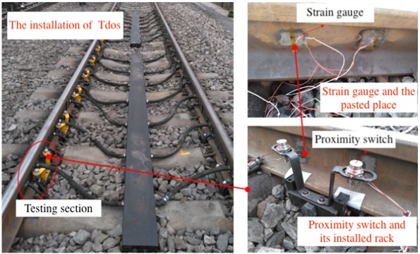
4.1. The installation of the wayside detection devices
The wayside detection system is installed on a heavy-haul railway in China, which is about 2 km away from the nearest station. When selecting the installation location, the system considers factors such as construction convenience, vehicle passing speed, and whether it is a long straight section, as well as network and power supply system issues. The line is divided into heavy load and empty load. Vehicles on the empty load line pass through the testing area after leaving the station, with an average passing speed of about 60 km/h. Vehicles on the heavy load line enter the station after passing through the testing area, with an average passing speed of about 30 km/h.
The wheel-rail force detection devices are installed simultaneously on the empty and heavy load line, arranged on both sides of the rails. There is a total of 14 channels on each steel rail, with a total of 56 channels. At the same longitudinal position where the strain gauges are pasted, a proximity switch is installed to detect the time when the wheelsets enter/exit the testing section. The installation effect of the wheel-rail force detection test section is shown in Fig. 5.
Fig. 5Installation effect on heavy load line
4.2. The testing calibration of the wayside detection devices
Following the installation of the wayside detection system, it is essential to calibrate the testing channels to achieve accurate wheel-rail force measurements. This calibration process involves determining the calibration coefficient, which is necessary for converting the electrical signals generated by the detection system into meaningful measurement quantities. The wheel-rail force calibration process utilizes a specialized calibration device, as depicted in Fig. 6. This device comprises a top seat, a hydraulic jack, a pressure sensor, and two steel wire ropes. During calibration, the test section is loaded using the hydraulic jack, and both strain signals and loading signals are recorded. These signals are then used to calculate the calibration coefficients for each detection area. The calibration procedure involves loading the test section three times, with the calibration coefficients being calculated for each loading. The average of these three calibration coefficient values is then used as the final calibration result for the corresponding channel. Fig. 7 illustrates the relationship between the loading signal from the force gauge and the strain signal from the steel rail. The consistent relationship observed between these signals indicates that the calibration process has achieved good linearity, ensuring that the system can accurately translate electrical signals into reliable wheel-rail force measurements.
Fig. 6Wheel-rail force calibration device
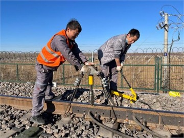
Fig. 7Variation curve of calibration signal and loading signal
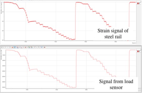
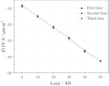
Fig. 8 presents the calibration conversion results for the vertical force detection channel on the right side of the 13th track span of the heavy load line. The calibration processes conducted on this channel demonstrate excellent linearity, with no deviations observed in the test outcomes, indicating a high level of detection accuracy. Similarly, as shown in Fig. 9, the calibration results for the empty load line closely align with those of the heavy load line, achieving a similarly strong calibration effect. The consistency observed between the calibration effects on both lines confirms the reliability of the system across different loading conditions. Calibration coefficients for wheel-rail forces are determined for each detection channel on both the heavy and empty load lines. These coefficients are essential for ensuring precise and reliable measurements in the monitoring and maintenance of the railway infrastructure.
On-site calibration employed a portable hydraulic load frame to sweep known wheel-rail force levels and construct voltage-force curves for each channel. Multiple passes on a reference wagon confirmed stable gains and negligible drift across the test window. Application of the conversion aligned sensor outputs with impact forces for subsequent field inference. Per-channel, site-specific conversion from voltage to force was established with repeated passes to confirm stable gains and negligible drift over the test window. Installation covered the heavy-load and empty-load lines on the instrumented section, providing consistent calibration behaviour across directions. Separation of empty and loaded conditions is retained in subsequent analysis to reflect differences in preload and compliance.
Fig. 8Calibration results for heavy load line
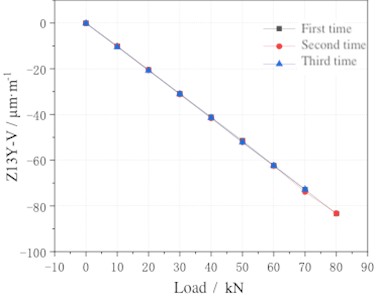
Fig. 9Calibration results for empty line
5. Analysis of wheel-rail force measurement data
The wayside detection system collected a substantial amount of wheel-rail force signal data from passing vehicles. Over a ten-day period, 80,541 vehicles of various models are monitored, with the majority being C80 trucks. Among the collected data, 20 abnormal wheel-rail impact signals were identified, comprising 4 from trains on the down line and 16 from trains on the up line.
When a normal train passes through the detection section, the wheel-rail force signals exhibit no significant abnormalities. Fig. 10 illustrates the original signal of the wheel-rail force for a normal train. The data shows that although slight fluctuations occur between the wheelsets of the vehicle, the strain values of the electrical signals remain around 130 µm/m. This consistency in the raw data indicates the absence of abnormal wheel-rail force fluctuations, allowing for clear identification of the positions of different wheelsets and vehicle signals.
Fig. 10Wheel-rail force signal of normal train (single channel)
a) Wheel-rail force signal for all wheels on one side of a train
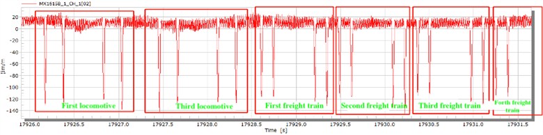
b) Partial Enlarged Image
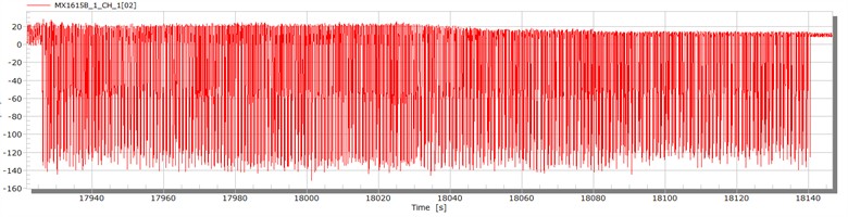
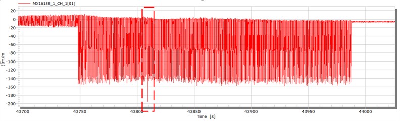
In contrast, Fig. 11 presents the original signal for an abnormal wheel-rail impact. The vehicle was fully loaded, and the wheels experienced significant wheel-rail impact, with an impact equivalent of approximately 1.397. To convert the strain signal into a wheel-rail force signal, the data is divided by the calibration coefficient. After applying this conversion, the resulting abnormal train wheel-rail impact force, shown in Fig. 12, indicates a maximum impact force of approximately 171 kN, which triggered an early warning signal.
The system effectively monitors and identifies abnormal wheel-rail interactions, crucial for maintaining the safety and efficiency of railway operations.
Fig. 11Raw data of abnormal wheel-rail impact
a) Abnormal signal in a train
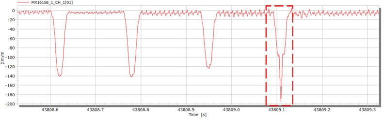
b) Partial enlarged image
Fig. 12Conversion results of abnormal train wheel-rail impact force
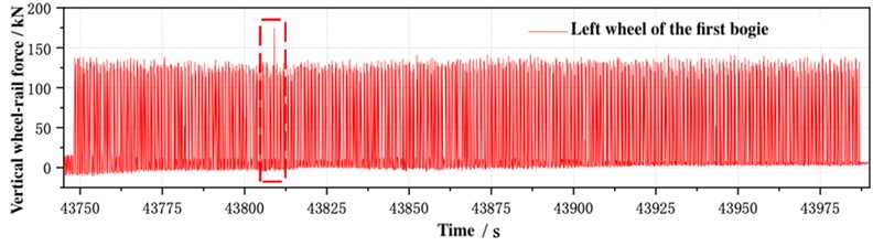
a) Abnormal signal of wheel-rail force after actual measurement conversion
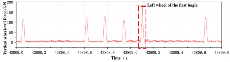
b) Partial enlarged image
According to the system detection, the operating speed of the vehicle with abnormal wheel-rail force signal mentioned above is 41.2 km/h, and the average axle load of the vehicle is 24.3 t. The wheel-rail impact mentioned above is substituted into the mapping relationship between wheel flat and wheel-rail force compiled in Section 3 for conversion. At this time, the length of the wheel flat should be 7.3 mm, triggering an alert.
By tracing the origin of the wheel, the alarm situation of the TPDS on the same line was found, as shown in Fig. 13. From the alarm data of the TPDS, it can be seen that the alarm situation of the TPDS is consistent with the warning signal of the wayside detection device, which is a level 3 warning. At the same time, the vehicle number and model can be matched.
A representative train yields an inferred flat length of 7.3 mm based on the converted impact force and operating speed in Fig. 12. The same vehicle appears in the TPDS records on the corresponding date, as shown in Fig. 13. Across a ten-day observation window on the instrumented section, each warning generated by the TODS matched TPDS records for the same vehicles, indicating consistent external validity under operational conditions.
Fig. 13Alarm information for the same vehicle from TPDS
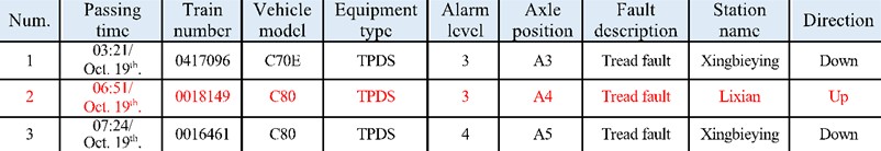
In addition, within ten days of data collection, each warning alarm condition can correspond to the TPDS. Compared with the TPDS, the TODS can indirectly obtain damage characteristics of wheel tread such as flat length and depth by applying the mapping relationship studied earlier, achieving better feature detection effect and good reliability. Validation integrates physics-based dynamic modelling, site-specific calibration, and independent operational records. Accuracy holds within the studied speed and axle-load ranges on the heavy-haul line. Future work will include direct depot gauging of flat length to expand the validated envelope.
6. Conclusions
This study presents a validated approach for real-time evaluation of wheel flats in heavy-haul railway wheelsets, grounded in the integration of dynamic modelling and field monitoring. Unlike conventional detection systems that rely on discrete thresholds or indirect indicators, our method quantitatively links wheel-rail impact forces with flat lengths under various operational speeds. This article has the following conclusions:
1) Dynamic behavior characterization: Simulation results reveal that the variation of wheel-rail impact force with respect to wheel flat length and vehicle speed is nonlinear and load-dependent. Specifically, empty and loaded vehicles exhibit distinct force trends across the 10-80 km/h range, which are effectively captured through polynomial fitting.
2) Operational classification framework: By incorporating vehicle load state and impact response, a three-level flat length classification system was derived, offering improved alignment with real operational scenarios compared to static depot criteria.
3) System reliability and accuracy: The TODS, featuring a dense 56-channel sensor layout and hydraulic calibration scheme, demonstrated robust performance in field deployment. Comparative analysis with TPDS confirmed its enhanced capability in capturing impact features and inferring flat dimensions.
4) Photographic documentation of flats was not collected during the ten-day field window; future deployments will include depot photo inspection for a subset of flagged wheelsets to provide an additional visual reference alongside TPDS records.
Overall, this research transforms rigid-flexible modeling from a purely theoretical tool into a practical basis for fault detection, offering traceable, real-data-calibrated diagnostics. The approach enhances detection sensitivity and diagnostic specificity, paving the way for predictive maintenance strategies in freight railway systems. Future work may expand the model to other wheelset defects and optimize sensor layouts for multi-axle identification.
References
-
W. Zhai, S. Stichel, and L. Ling, “Train-track coupled dynamics problems in heavy-haul rail transportation,” Vehicle System Dynamics, Vol. 63, No. 7, pp. 1187–1240, Jul. 2025, https://doi.org/10.1080/00423114.2025.2494834
-
Y. Sarikavak and K. Goda, “Dynamic wheel/rail interactions for high-speed trains on a ballasted track,” Journal of Mechanical Science and Technology, Vol. 36, No. 2, pp. 689–698, Feb. 2022, https://doi.org/10.1007/s12206-022-0117-7
-
Z. Wen, G. Xiao, X. Xiao, X. Jin, and M. Zhu, “Dynamic vehicle-track interaction and plastic deformation of rail at rail welds,” Engineering Failure Analysis, Vol. 16, No. 4, pp. 1221–1237, Jun. 2009, https://doi.org/10.1016/j.engfailanal.2008.08.001
-
Z. Shen, “On principles and methods to reduce the wheel/rail forces for rail freight vehicles,” Vehicle System Dynamics, Vol. 20, No. sup1, pp. 584–595, Jan. 1992, https://doi.org/10.1080/00423119208969424
-
J. Wang, P. Wu, and Z. Tang, “A study on the effect of additional impact force caused by wheel flat on the stress spectrum of vehicle axles,” (in Chinese), Journal of Railways, Vol. 28, No. 1, pp. 39–43, 2006.
-
M. Fermér and J. Nielsen, “Wheelset rail contact forces for flexible versus solid wheels due to tree regulations,” Vehicle System Dynamics, Vol. 23, No. 1, pp. 142–157, 1994.
-
R. V. Dukkipati and R. Dong, “Impact loads due to wheel flats and shells,” Vehicle System Dynamics, Vol. 31, No. 1, pp. 1–22, Jan. 1999, https://doi.org/10.1076/vesd.31.1.1.2097
-
“Railway freight vehicle depot repair regulations,” (in Chinese), China Railway Publishing House, Beijing, China, 2012.
-
“A new system for detection track load and vehicle status safety,” (in Chinese), Scientific Research Institute of the Ministry of Railways, Beijing, China, 1998.
-
R. Liu and Y. Wang, “Principle and application of truck performance detection system (TPDS) for railway freight vehicle operation status,” (in Chinese), China Railway Publishing House, Beijing, China, 2008.
-
L. Ling, X. Li, X. Chai, and H. Zhang, “Development of ground detection system for the operation status of high-speed railway EMUs,” (in Chinese), Railway Construction, Vol. 83, No. 1, pp. 71–75, 2015.
About this article

This work is support by the Key Research Project of China State Railway Group Co., Ltd. (N2024T009).
The datasets generated during and/or analyzed during the current study are available from the corresponding author on reasonable request.
Ziqi Jin: conceptualization, software, writing-original draft, visualization. Xinyu Peng: validation, writing-review and editing. Zhenyu Zhang: validation, writing-review and editing. Yongfu Nie: validation, writing-review and editing. Kang Su: funding acquisition, conceptualization, validation, writing-review and editing.
The authors declare that they have no conflict of interest.
