Abstract
In order to explore the impact of near surface ore body mining on the stability of overburden and surface dangerous rock masses, a Phosphate Mine was used as the engineering background. On-site investigation method was adopted to clarify the stability conditions of the surface dangerous rock. Numerical analysis software was used to simulate the evolution laws of overburden deformation, stress, and plastic zone. The research results indicate that the development of interlayer structural planes in the surrounding rock of the roof of the mining area can easily cause the collapse of the roof slab or sheet. The strata are hard and brittle in lithology, with developed rock fractures. Dangerous rock blocks are formed under the combination of fissures and rock layers. The mining disturbance generated during the mining process is relatively small. The impact on the rock layers, adjacent mining sites, and surface stability is weak. The surface is less affected by the mining of underground ore bodies and has not reached the maximum allowable value. Under the condition of first mining the ph1# ore body and then mining the ph2# ore body, the displacement of the overburden is relatively small. There is no distribution of connectivity in the plastic zone in the mining pillars, mining areas, and overburden. The research results can provide theoretical reference for the feasibility analysis of near surface ore body mining in similar mines.
Highlights
- The development of interlayer structural planes in the surrounding rock of the roof of the mining area can easily cause the collapse of the roof slab or sheet.
- The strata are hard and brittle in lithology, with developed rock fractures. Dangerous rock blocks are formed under the combination of fissures and rock layers.
- The surface is less affected by the mining of underground ore bodies and has not reached the maximum allowable value.
1. Introduction
In recent years, the increasing demand for mineral resources has led to accelerated mining operations [1-3]. Some mines, considering the impact on the surface ecological environment [4, 5] and immature technical and mining conditions in the early stage, have reserved ore bodies in near surface areas. With the depletion of mineral resources, the extraction of reserved ore bodies has become the foundation for sustainable mining. Therefore, the impact of mining in the near surface area on the surface, namely controlling the stability of overburden, is particularly important.
Scholars have conducted extensive research on disasters such as surface subsidence caused by underground mining [6-10]. Wang et al. used field investigation observation and numerical simulation coupling technology (FDM-DEM) to study the incubation law of rock slope collapse, and clarified that underground coal mining operations were the main factor causing mountain slope collapse [11]. Ma et al. relied on specific disaster cases and used methods such as on-site investigation, geological mapping, and drone aerial photography to clarify that high-speed bedding landslides were formed by the combined effects of engineering activities and climate change, with the main contributing factor being disturbance from open-pit mining [12]. Yang et al. used the long-term underground mining activities in the high and steep karst mountainous areas of southwestern China as a case study to illustrate the formation law of slope collapse caused by underground mining disturbance [13]. Leng et al. used the landslide disaster of mountain slopes caused by underground mining in southwestern karst mountainous areas as the research background, and based on the Hoek Brown strength criterion, constructed a “strength reduction method” applied to slope stability, clarifying that karst action and underground mining were the main factors that have adverse effects on slopes [14]. Li et al. used the collapse disaster of limestone mining sites as a case study, and the research results showed that strong folding orogeny laid the structural framework in the area, which was a necessary condition for the development of collapse. The coupling effect of abundant rainfall, ore body mining activities, and other internal and external forces was the main triggering factor of collapse disasters [15]. From the relevant research results conducted by the scholars mentioned above, it can be seen that the research mainly focuses on the impact of mining deeply buried ore bodies on the surface and overburden. The research on mining near surface ore bodies is still not deep enough, especially the impact mechanism of the mining sequence of multiple layers of ore bodies near the surface on the stability of overburden is not clear enough.
Based on specific engineering cases, on-site investigation methods were used to clarify the impact of near surface ore body mining on the surface. Further, numerical simulation research methods were used to establish a three-dimensional engineering scale mechanical analysis model. The influence of the mining sequence of near surface multi-layered ore bodies on the stability of overburden was simulated. The mechanism of the impact of near surface ore body mining on the stability of overburden was revealed. The research results can provide theoretical reference for the feasibility analysis of near surface ore body mining in similar mines.
2. Geological and mining overview of the mining area
2.1. Terrain and landforms in the mining area
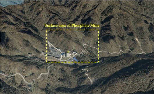
The mountains and water systems in the mining area are distributed in a northeast direction, with high mountains, deep valleys, and steep terrain. The elevation ranges from 805.4 to 1539.0 m, with a relative height difference of generally 400 to 500 m and a maximum of 733.6 m, belonging to the Zhongshan landform type. The surface is mainly composed of mountain slopes with an angle of 42-61°. Topography and geomorphology of the mining area is shown as Fig. 1.
Fig. 1Topography and geomorphology of the mining area
2.2. Engineering geological conditions
The Ph1# direct roof and floor of the industrial phosphate deposit in the mining area belong to semi hard to hard carbonate rock formations, but the interlayer structural planes of the direct roof are developed, which can easily cause geological problems such as roof collapse. The overall degree of karst development is weak, with some areas ranging from weak to moderate. The direct roof of the secondary industrial phosphate rock layer Ph2# is also a semi hard to hard carbonate formation, while the floor is a semi hard clastic rock formation (including potassium shale). During the mining process of phosphate ore, due to the adjustment of stress balance conditions in the mine, there may be local “bottom bulge” deformation problems in the areas where structural fractures are developed. According to practical experience in mining similar phosphate mines, the swelling height is generally between 0.3 and 0.50 m. The extension length of the F29 fault in the northeast and near east-west directions of the mining area is 350 m to 2150 m, resulting in a vertical drop of 5m to 44m in the ore layer, which damages the continuity of the phosphate ore layer. According to the relevant standards of specification [16], the engineering geological type of the mining area belongs to the fourth category and second type, which is “soluble salt rock deposits mainly composed of carbonate rocks with moderate complexity in engineering geological exploration”.
The Ph1# phosphate deposit belongs to a shallow buried (133 m), gently inclined (5°), thin layered (2.5 m) sedimentary phosphate rock deposit. The Ph2 # phosphate deposit belongs to a shallow buried (136 m), gently inclined (dip angle of 5°), thin layered (3.6 m), low-grade sedimentary phosphate rock deposit. Ph1 # occurs in the upper part of Ph2#, with a spacing of 0-13 m between Ph1# and Ph2#, with an average spacing of 8 m. The Ph1# phosphate deposit is produced in layers, and the fault cuts the phosphate deposit into nineteen pieces, causing a vertical drop of 0-21 m in the deposit. The Ph1 # phosphate deposit slopes towards the south or northeast, with a dip angle of 3° to 10° and an average dip angle of 5°. The single engineering thickness of Ph1 # industrial phosphate ore layer is 0.1-6.2 m, with an average thickness of 2.5 m. The Ph2 # phosphate deposit slopes towards the south or northeast, with a dip angle of 5° to 14° and an average dip angle of 7°. The single engineering thickness of Ph2 # industrial phosphate ore layer is 0.2-10.2 m, with an average thickness of 3.6 m.
2.3. Rock mechanics parameters
Four types of blocky rocks were selected in typical underground areas, including dolomite (roof), Ph1 # ore body, dolomite (interlayer), and shale (floor). Mechanical drilling machines are used to obtain standard samples in large rocks. The moisture content of the specimen is in its natural state. The tested indicators include natural gravity, elastic modulus, Poisson’s ratio, compressive strength, tensile strength, cohesion, and internal friction angle. Due to the size difference between indoor rock mechanics test samples and rock masses in engineering, it is necessary to convert rock mechanics parameters into engineering scale rock mechanics parameters. The commonly used empirical methods include RQD classification method, CSIR classification method for jointed rock mass, Q system classification method, GSI classification method, and geotechnical specification method for engineering treatment of physical and mechanical test parameters of mining rocks [17]. Comprehensive reduction of underground rock mass mechanical parameters is obtained. The mechanical parameters of the filling body are obtained through filling body tests. The mechanical parameters of the fault are obtained through indoor tests, as shown in Table 1.
Table 1Mechanical parameters of mineral rock mass
Rock material | Natural gravity (kN/m3) | Elastic modulus (GPa) | Poisson’s ratio | Cohesion (MPa) | Internal friction angle / (°) |
Dolomite (roof) | 27.01 | 10.52 | 0.24 | 8.23 | 35.37 |
Ph1# ore | 28.74 | 6.87 | 0.31 | 4.36 | 31.12 |
Dolomite (interlayer) | 26.94 | 10.61 | 0.24 | 8.65 | 35.81 |
Ph2# ore | 28.85 | 7.23 | 0.30 | 4.02 | 30.61 |
Shale (bottom plate) | 26.43 | 8.47 | 0.18 | 5.65 | 32.13 |
Backfill | 18.10 | 8.01 | 0.21 | 2.81 | 37.60 |
Fault | 23.21 | 3.12 | 0.35 | 1.23 | 22.31 |
3. Investigation and analysis of underground mining and surface stability
3.1. Current situation of underground mining
The phosphate mining area is divided into three mining areas based on the main faults and exploration lines, and considering alternative pit sites. Each mining area can operate relatively independently, and three mining areas will be constructed simultaneously. The first mining area will be inspected first, and the second and third mining areas will be inspected later. The mine will be constructed in two phases. The first phase is above an elevation of 890 m. The ore body below an elevation of 890 m belongs to the second phase, of which only the third mining area has a second phase project. At present, the infrastructure construction of the 500000 t/year mining project in the first phase and first mining area has been completed and passed the safety facility acceptance. The third mining area is still in the construction stage. The scope of this study is mainly located in the first mining area.
According to the on-site investigation underground, the surrounding rock of the direct roof of the Ph1# main industrial phosphate ore layer is light gray thin to medium thick layered mud powder crystal dolomite interbedded with gray yellow thin layered cloudy mudstone, with moderate rock hardness. The average RQD value of the rock is 72 %. The integrity of the rock mass is moderate. The interlayer structural planes of the direct roof surrounding rock are developed. The thin layer of cloud like mudstone sandwiched by dolomite is prone to collapse in block or sheet form under the action of water and negative pressure. The horizontal orientation of the roof strata in local tunnels can easily cause the roof to collapse in a sheet-like manner. On-site investigation found that there was roof collapse in some sections.
The indirect roof is composed of dolomite interbedded with mudstone dolomite, belonging to the hard rock category. The average RQD value of the rock is 71 %. The overall integrity of the rock mass is moderate. After the tunnel is exposed, except for local roof collapse in areas with developed structural fissures. The possibility of severe rock collapse is generally small. The stability of the surrounding rock of the top plate of Ph1# phosphate deposit is poor to moderate.
3.2. Stability analysis of surface conditions
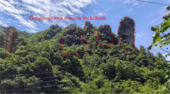
There are a total of 19 hazardous rock formations developed in the mining area, all of which are dolomite from the Dengying Formation, with elevations ranging from 1000 to 1200 m. The scale of dangerous rock masses is mainly small, with 18 small ones and only 1 medium-sized one. The 19 hazardous rock formations are mostly located on steep cliffs or steep slopes, with natural slopes that are nearly vertical (see Fig. 2). Unloading cracks occur at the exposed surface, causing relaxation deformation and failure, providing favorable terrain conditions for the formation and development of landslides. The dangerous rock masses in the mining area can be divided into two categories: under stable and basically stable. There are 13 under stable dangerous rock masses and 6 basically stable dangerous rock masses.
The main material composition of the disaster body is composed of dark gray, gray white thin to medium layered powder crystal dolomite in the middle and lower sections of the Lower Cambrian Dengying Formation and the Hamajing Formation, containing sand debris powder crystal dolomite. This stratum is hard and brittle in lithology. Due to differences in siliceous content in some areas, it is prone to form towering blocks or columns. The surface is prone to steep cliff landforms, leading to landslides and rockfalls.
The collapse area has strong tectonic activity. Multiple faults and folds have been formed. Therefore, the integrity of the rock mass structure is poor, the structure is fragmented, and joint fissures are developed. The geological conditions provide favorable conditions for the formation of collapsed rocks. The area has high mountains, steep slopes, and high exposed surfaces, with developed rock fractures. Under the unloading effect of the steep slope, the fractures of the rock continue to deepen and widen, leading to the evolution of the slope fractures into tension fractures. The dangerous rock blocks are gradually stripped from the bedrock, forming dangerous rock blocks under the combination of fractures and rock layers.
After atmospheric rainfall infiltrates along the joints and fissures of the rock mass, it increases the weight of the rock mass. One of its effects is that water infiltrates into the fissures of the rock mass, saturating the structural planes and reducing their mechanical strength. Secondly, after rain, the degree of short-term water filling in the rock mass is relatively high. The dynamic and static water pressure inside the rock mass increases, which is not conducive to the stability of the rock mass. According to on-site investigations, landslides and rockfalls in the area mostly occur during the rainy season, indicating that atmospheric rainfall is the main triggering factor for the formation and development of landslides and rockfalls. Whenever there is a flood season or earthquake, the possibility of collapse is greater and the frequency is higher. The broken rock structure and good free space conditions are the internal factors for the formation and deformation of hazardous rocks, while unloading and rainwater are the external factors that promote deformation. Under the comprehensive action of various factors, hazardous rocks are prone to detachment from the parent rock and deformation and failure. For the dangerous rock masses in the mining section, manual cleaning, static blasting, and the installation of passive protective nets are mainly adopted for prevention and control.
Fig. 2Dangerous rock mass group on the hillside
4. Establishment and analysis of numerical simulation models
4.1. Fine modeling method for multi-source data coupling
The phosphate mining area is characterized by mountainous terrain. The highest altitude in the research area is around 1400 m, the lowest altitude is around 1000 m. The relative height difference is about 400 m. The surface of the mining area is a mountainous area with significant changes in elevation. To obtain reasonable analysis results of surface displacement after mining disturbance, the existence of surface terrain model must be considered in 3D modeling. The role of terrain models is to clearly express surface information, including the undulating changes and elevations of mountains. A surface model of the phosphate mining area was established by using MIDAS-GTS/NX software [18].
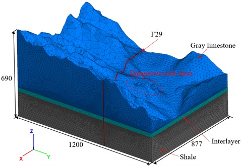
Based on the drawings provided by the mine, in the MIDAS-GTS/NX software, the establishment of three-dimensional solid models of the ore body, mining area, and pillar in each mining area is achieved through extended commands. The established surface model has been expanded into a solid model. The previously generated goaf entity is displayed in the software. According to the requirements of calculating the spatial range, the origin and corresponding boundary dimensions of the overall model are determined. The mining entity is embedded into the overall model to form the mining area in the overall model. The overall overview of the model is shown in Fig. 3. The length of model is 1200 m. The width is 877 m. The height is 349-690 m. The surface mountainous areas in the mining area have significant undulations, with the highest altitude in the study area being around 1400 m and the lowest altitude being around 1000 m, with a relative height difference of about 400 m. The middle phosphorus layer adopts the pre controlled roof and pillar mining method, with a mining pillar size of 4 m×4 m in the mining area, arranged at intervals of 8m along the strike and dip. The size of the mining area is established based on the actual situation, using a 1:1 ratio. The size of the mining area shall be determined according to the latest design drawings of the mine. To replicate the mine's actual conditions as closely as possible, providing a foundation for more accurate simulation of the mine's overall response after the ore body has been mined.
Fig. 3Overview of the overall model
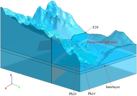
This model includes surface topography, ore bodies, various rock masses, mining pillars, F29 faults, and other structures. This model has established a total of 1237 entities. The model includes five types of ore bodies: dolomite (roof), Ph1# ore, dolomite (interlayer), Ph2# ore, and shale (bottom plate), and backfill. Due to the thin surface soil, it has little impact on this study and there is no separate layer of model.
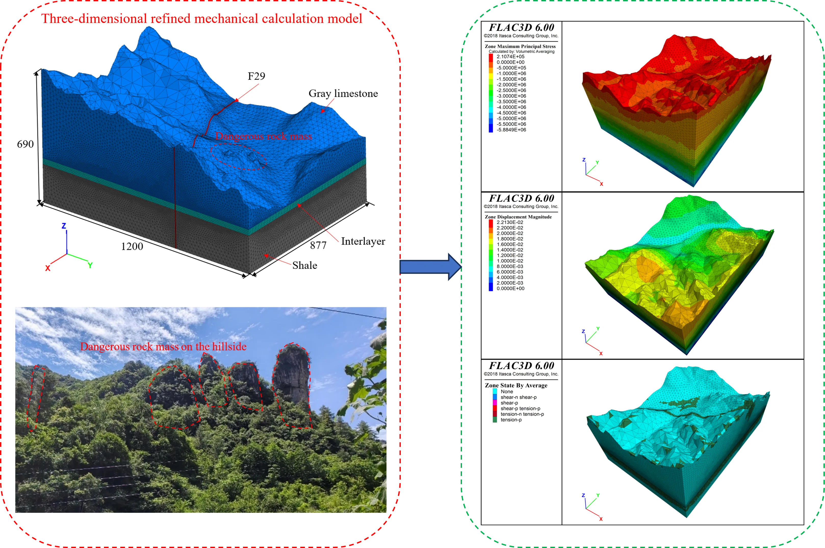
Fig. 4Three-dimensional refined mechanical calculation model (unit: m)
Considering the actual situation, the mining model is relatively large, and for non-research focus areas, the grid division is relatively sparse. For the filling bodies, pillars, and bars in the mining area, they are the focus of this study, and the grid division is relatively dense. The mesh density of the filling body, ore pillars, and strip pillars in the mining area is 4 m, divided into 1m calculation nodes. The mesh density of the interlayer is 8 m. The mesh density of the surrounding rock is 20 m. After the final grid division, the model has 413663 nodes and 238632 units. The neutral file of the overall mine model was exported from MIDAS-GTS/NX software, including node and unit information of the model. The MIDAS-FLAC model conversion program was used to convert node unit information in the Midas model into node unit information in FLAC. A *.f3grid file that conforms to the FLAC3D data format was generated. The import command in FLAC3D's Grid was used to import saved *.f3grid files. A comprehensive analysis model of the mining area containing ore bodies and rock layers was generated in FLAC3D, as shown in Fig. 4.
All nodes on the plane are fixed in the direction, i.e. sliding hinge supports. All nodes on the plane are fixed in the direction, that is, sliding hinge supports. All nodes on the lowest plane in the direction are fixed in the , , and directions, that is, fixed hinge supports. The maximum mining depth in the mining area is about 200 m from the surface, and the geological structure of the area is simple, so the calculation of the initial stress field only considers the influence of gravity.
4.2. Simulation sequence of ore body mining
The development system of the Ph1# mining layer in the mining area has been completed according to the design and has the conditions for ore recovery, while the development system of the Ph2# mining layer has not been built yet. The grade of phosphate ore in the Ph1# mining layer is higher than that in the Ph2# mining layer. Ph1# occurs in the upper part of Ph2#, with a distance of 0-13 m between Ph1# and Ph2#, with an average distance of 8 m. The main purpose of this article is to explore the mechanism of the impact of near surface ore body mining on the stability of overburden. Ph1# ore block pre controlled roof and pillar mining method, leaving 4 m×4 m ore pillars, arranged at intervals of 8m along the strike and dip. Ph2# ore block filling method, with a length of 100 m along the strike and a length of 100 m along the dip, leaving 6 m wide pillars between the ore blocks. Numerical simulation research was conducted using the simulation sequence of mining Ph1# → mining Ph2# → filling Ph2#.
4.3. Stability assessment criteria
According to the allowable values for displacement and deformation required by different protection levels specified in relevant regulations [19-20], the criteria for determining the impact of underground mining on surface stability in mining areas are deformation ±2 mm/m, inclination ±3 mm/m, and curvature ± 0.2×10⁻³/m.
The criterion for determining the deformation and displacement of underground rock formations based on the analogy of underground mining experience is that displacements below 20 mm have little effect on the stability of the rock mass. A displacement of 20-50 mm can maintain the stability of the rock mass. Displacement on the order of 50-100 mm poses potential stability issues for the rock mass 100 mm belongs to the problem of large deformation displacement, and there is a phenomenon of rock mass failure, which may also occur on a large scale. In addition to using deformation displacement as a criterion, comprehensive judgment is assisted by stress magnitude and plastic zone distribution. This numerical simulation used indicators such as maximum unbalanced force, rock stress, surface displacement, and plastic zone distribution to determine mining stability.
5. Analysis of results based on numerical simulation
5.1. Stress evolution law
The mining of underground ore bodies can cause disturbance to the distribution of geo-stress, and even affect the distribution and magnitude of geo-stress in the entire area. In order to analyze the possible impact of underground mining on the surface, the disturbance of overlying rock stress under mining conditions can be analyzed to reflect the stability of the rock formation during the mining process. The stress evolution laws are showed in Fig. 5-Fig. 8.
Fig. 5Maximum principal stress of the overall model
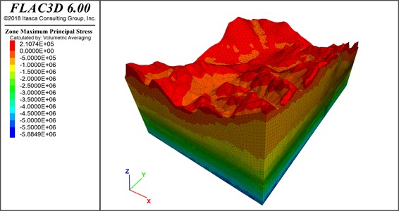
Fig. 6Minimum principal stress of the overall model
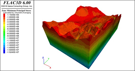
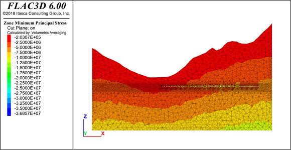
Fig. 7Maximum principal stress of the model typical cross-section
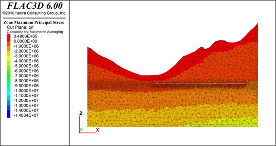
From Fig. 5-Fig. 8, it can be seen that the stress on the surface, rock layers, and surrounding rock of the mining area after mining the intermediate phosphate layer ore body gradually increases with depth, showing a regular increasing trend overall. Due to the unloading effect of mining in the underground ore body mining area, the trend of stress distribution changes and stress concentration forms in the goaf. There is tensile stress on the surface, shallow rock layers, and roof. The maximum tensile stress on the surface is 0.51 MPa, which is lower than the tensile strength of dolomite (roof) of 0.91 MPa, indicating that the possibility of tensile failure on the surface is relatively small. In the goaf, compressive stress is mainly present in the pillars, with a maximum compressive stress of 3.5-4 MPa, which is lower than the compressive strength of the middle phosphorus layer of 8.35 MPa, indicating that the possibility of compressive failure in the pillars is relatively small.
Fig. 8Minimum principal stress of the model typical cross-section
5.2. Displacement evolution law
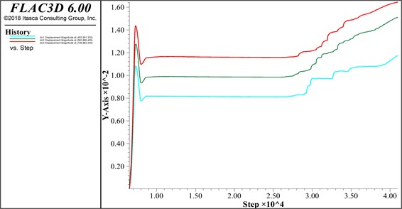
After mining the underground ore body, it will cause deformation and displacement of the surrounding rock mass. The displacement will propagate along the rock layer and develop to the surface. The amount of surface displacement and deformation can indirectly reflect the stability of the rock layer during the mining process. The surface displacement and rock displacement cloud maps after mining the underground ore body are shown in Fig. 9 and Fig. 10. Three displacement monitoring points were arranged at the dangerous rock mass on the surface, namely , , and . Through displacement monitoring points, the displacement changes at the surface dangerous rock mass during the underground mining process can be monitored throughout the entire process. The surface displacement monitoring curve is shown in Fig. 11.
Fig. 9Displacement magnitude of the overall model
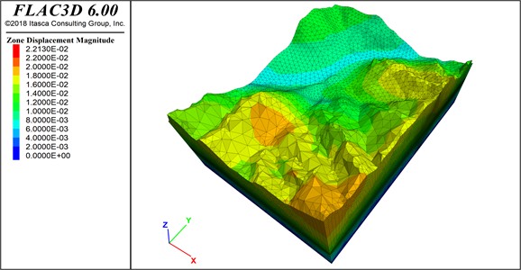
From Fig. 9 and Fig. 10, it can be seen that after mining the lower phosphorus layer, there is a displacement of 1.62 cm in the surface and rock layers. The deformation amount is 0.092 mm/m, which is less than the judgment standard of 2 mm/m. The results indicate that the impact of mining the ore body on the surface is within a controllable range. The impact is relatively small. A displacement of 2.12 cm occurred in some areas of the roof of the underground goaf. Mainly affected by the mining of the lower phosphate layer ore body, the deformation of the surrounding rock mass in the goaf of the middle phosphate layer is exacerbated. The displacement of most areas in the goaf is less than 2.0 cm. According to the rock mass stability criterion, displacements below 20 mm have little effect on the stability of the rock mass. A displacement of 20-50 mm can maintain the stability of the rock mass. The results indicate that the impact of mining in the first mining area on the upper rock layers is relatively small and within a controllable range.
Fig. 10Displacement magnitude of the model typical cross-section
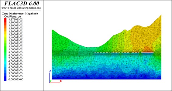
Fig. 11Surface displacement monitoring curve
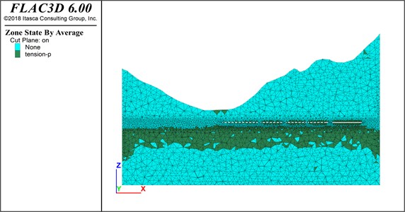
5.3. Plastic zone evolution law
Qualitative analysis methods were used to analyze the connectivity of plastic zones in the ore pillars, mining areas, and overburden layers. According to the analysis of the simulation mining calculation results, it can be concluded that the 4 m×4 m pillars left in the mining of the Ph1# ore body have not yet experienced plastic zone connectivity with the pillars between the mining site (Fig. 12 and Fig. 13). After the completion of the mining of the ph1# ore body, the phosphorus layer of the ph2# ore body was mined, forming a plastic zone distribution in the past. Its failure was suspended with the decrease of stress, and an ongoing plastic zone distribution had not yet been formed. It can be determined that the mining sequence and structural parameters of the mining site, which first mined the ph1# ore body and then mined the ph2# ore body, have a relatively small impact on the overburden. During the underground mining process, regular observation and preventive measures should be taken for surface and rock deformation.
Fig. 12Plastic zone of the overall model
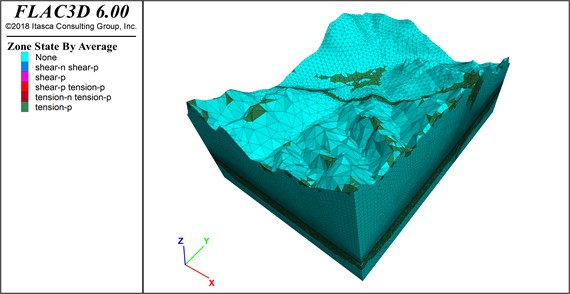
Fig. 13Plastic zone of the model typical cross-section
6. Conclusions
Base on the specific mining projects, on-site investigation methods were used to analyze the stability of dangerous rock masses on mountain slopes and the roof of underground mining sites. A three-dimensional refined model of the mining area at an engineering scale was established based on MIDAS-GTS/NX and FLAC3D. The evolution laws of rock stress, surface and rock displacement, and rock plastic zone under mining conditions were studied. The main conclusions are as follows:
1) The development of interlayer structural planes in the roof rock of the mining area can easily cause the collapse of the roof slab or sheet. The strata are gradually stripped off from the bedrock by the unloading effect of high and steep slope bodies. The dangerous rock blocks are formed, under the combination of fractures and rock layers.
2) The ph1# ore body should be mined first. The mining disturbance generated during the mining process is relatively small. The impact on the rock layers, adjacent mining sites, and surface stability is weak.
3) The impact of underground mining on the surface is relatively small and has not reached the maximum allowable value. For the working condition of first mining the ph1 # ore body and then mining the ph2# ore body, the displacement of the overlying rock layer is relatively small. There is no distribution of connectivity in the plastic zone in the mining pillars, mining areas, and overburden.
References
-
H. Sun et al., “The current status and development demand analysis of certified reference materials for strategic critical metal minerals,” Rock and Mineral Analysis, Vol. 43, No. 2, pp. 375–396, 2024, https://doi.org/10.15898/j.ykcs.202308030121
-
K. Tang et al., “Research and application of comprehensive evaluation system of ecological environmental impact of mineral resource development in nature reserves,” Safety and Environmental Engineering, Vol. 31, No. 5, pp. 239–248, 2024, https://doi.org/10.13578/j.cnki.issn.1671-1556
-
Q. Du et al., “Analyzing the surface subsidence pattern of deep mining in ecologically fragile areas of western China,” KSCE Journal of Civil Engineering, Vol. 29, No. 7, p. 100136, Jul. 2025, https://doi.org/10.1016/j.kscej.2024.100136
-
N. Anantrasirichai, J. Biggs, F. Albino, and D. Bull, “A deep learning approach to detecting volcano deformation from satellite imagery using synthetic datasets,” Remote Sensing of Environment, Vol. 230, p. 111179, Sep. 2019, https://doi.org/10.1016/j.rse.2019.04.032
-
Y. Fu et al., “Ground fracture development and surface fracture evolution in N00 method shallowly buried thick coal seam mining in an arid windy and sandy area: a case study of the Ningtiaota Mine (China),” Energies, Vol. 14, No. 22, p. 7712, Nov. 2021, https://doi.org/10.3390/en14227712
-
F. Wang, Q. Ren, X. Jiang, A. Jiang, C. Zhao, and W. Liu, “Engineering geology and subsidence mechanism of a mountain surface in the Daliang Lead-zinc Ore Mine in China,” Bulletin of Engineering Geology and the Environment, Vol. 81, No. 11, Oct. 2022, https://doi.org/10.1007/s10064-022-02983-7
-
F. Wang, Q. Ren, X. Jiang, J. Niu, and B. Chen, “Engineering geology and mechanism of multiple landslides in a large open-pit mine: the case of the Copper Mine in Qinghai Province, China,” Bulletin of Engineering Geology and the Environment, Vol. 82, No. 4, p. 147, Mar. 2023, https://doi.org/10.1007/s10064-023-03186-4
-
F. Wang et al., “Strata movement law based on progressive caving of the hanging wall: a case of study in Chaganaobao Iron-Zinc Mine,” Arabian Journal of Geosciences, Vol. 13, No. 21, pp. 1155–1170, Oct. 2020, https://doi.org/10.1007/s12517-020-06112-0
-
Wang Feifei et al., “Study on the formation and development mechanisms of surface subsidence in Chaganaobao iron-zinc mine,” Rock and Soil Mechanics, Vol. 41, No. 11, pp. 3757–3768, 2020, https://doi.org/10.16285/j.rsm.2020.0128
-
Wei Yuan et al., “Numerical simulation of surface subsidence caused by underground mining using discrete element software PFC2D,” Mining and Metallurgical Engineering, Vol. 43, No. 2, pp. 30–34, 2023, https://doi.org/10.3969/j.issn.0253-6099.2023.02.007
-
X. Wang et al., “Forensic analysis and numerical simulation of a catastrophic landslide of dissolved and fractured rock slope subject to underground mining,” Landslides, Vol. 19, No. 5, pp. 1045–1067, Feb. 2022, https://doi.org/10.1007/s10346-021-01842-y
-
G. Ma, X. Hu, Y. Yin, G. Luo, and Y. Pan, “Failure mechanisms and development of catastrophic rockslides triggered by precipitation and open-pit mining in Emei, Sichuan, China,” Landslides, Vol. 15, No. 7, pp. 1401–1414, May 2018, https://doi.org/10.1007/s10346-018-0981-5
-
Yang Z. P. et al., “The crack propagation and deformation failure law of slope with deep and large karst structural planes under mining action,” Journal of Geotechnical Engineering, Vol. 44, No. 8, pp. 1397–1405, 2022, https://doi.org/10.11779/cjge202208004
-
D. Leng, W. Shi, F. Liang, H. Li, and L. Yan, “Stability and deformation evolution analysis of Karstified slope subjected to underground mining based on Hoek-Brown failure criterion,” Bulletin of Engineering Geology and the Environment, Vol. 82, No. 5, p. 174, Apr. 2023, https://doi.org/10.1007/s10064-023-03211-6
-
H. L. Li et al., “Research on the formation mechanism of landslides coupled with internal and external dynamic geological processes: taking the collapse of upper Triassic limestone mines in Changdu, eastern Tibet as an example,” Journal of Geomechanics, Vol. 28, No. 6, pp. 995–1011, 2022, https://doi.org/10.12090/j.issn.1006-6616.2022062
-
“Exploration specification of hydrogeology and engineering geology in mining areas,” China Standard Publishing House, Beijing, GB/T12719-2021, 2021.
-
E. Hoek and E. T. Brown, “The Hoek-Brown failure criterion and GSI – 2018 edition,” Journal of Rock Mechanics and Geotechnical Engineering, Vol. 11, No. 3, pp. 445–463, Jun. 2019, https://doi.org/10.1016/j.jrmge.2018.08.001
-
Hao Yumeng and Jin Hongju., “Study on the catastrophe and stability analysis and prevention technology of giant traction landslide,” Journal of Hunan City University (Natural Science), Vol. 32, No. 2, pp. 12–18, 2023, https://doi.org/10.3969/j.issn.1672-7304.2023.02.0003
-
“Code for investigation of geotechnical engineering,” China Architecture and Building Press, Beijing, GB50021-2001(2009 edition), 2009.
-
“Code for design of nonferrous metal mining,” China Planning Press, Beijing, GB50771-2012, 2012.
About this article

This work was supported by the Natural Sciences Funding Project of Hunan Province (2024JJ6110, 2024JJ8049), Hunan Province Natural Science Foundation regional joint fund project (2025JJ70386), Application Basic Research and Soft Science Research Plan of Yiyang City (2024YR02), Project of Yiyang Social Science Achievement Review Committee (Y0416220), and aid program for Science and Technology Innovative Research Team in Higher Educational Institutions of Hunan Province.
The datasets generated during and/or analyzed during the current study are available from the corresponding author on reasonable request.
Wang Feifei wrote the initial draft (including substantive translation). Wu Yuexing carried out the software analysis. Jiang Anmin and Wu Kuan carried out the site investigation.
The authors declare that they have no conflict of interest.
