Abstract
Frame saws suffer from large unbalanced inertia forces, limiting operating speed and requiring heavy construction. This study aims to overcome these limitations by synthesizing a dynamically balanced main drive mechanism using a novel approach based on prescribed motion laws. The methodology involves proposing a crank-slider mechanism featuring a cam-actuated variable-length crank. The mechanism configuration with parallel spring is analyzed allowing for balancing inertia forces, achieved using a prescribed cosine slider motion law. For the considered configuration, the required variable crank length function (cam profile) and associated mechanism parameters (connecting rod length, spring stiffness) are analytically synthesized. The results of the carried-out numerical modeling demonstrate successful synthesis of a near-circular cam profile and very low pressure angles for the case studied. These findings show that synthesizing the saw drive kinematics based on force balancing requirements can theoretically eliminate inertial loads, offering the potential for higher speeds of saw frames and reduced loads. The synthesized near-circular cam profile suggests a pathway towards simpler manufacturing. The implications of successfully implementing such dynamically balanced frame saw mechanisms are potentially transformative for the sawmilling industry. Eliminating the primary inertial forces removes the major obstacle to increasing operating speeds. This could allow frame saws to operate closer to the optimal cutting speeds for wood (e.g., 40-50 m/s), leading to significant gains in productivity.
Highlights
- Controllable crank-slider with parallel springs is synthesized: a cam-actuated variable-length crank plus a prescribed cosine slider law cancel inertia forces over the full stroke.
- Closed-form formulae are obtained for r(φ), the minimum connecting-rod length, and the spring stiffness, using a line–circle tangency condition and force equilibrium at the stroke extremes.
- Modeling shows a near-circular fixed-cam profile and very low pressure angles (<4.2°), suggesting feasible cam–follower action and possible realization by an eccentric circular disc.
- Balanced motion invariants are given (cosine law), with peak constants B≈1.57 (velocity) and C≈4.935 (acceleration), providing practical guidance for sizing and selection.
- Primary inertial loads on the saw frame are theoretically eliminated, enabling higher speeds, reduced vibration and structure mass, and increased productivity in frame-sawing.
1. Introduction
The effective processing of wood and wood-based materials relies on foundational cutting technologies [1]. In frame sawing operations, success is interconnected with several factors, including insights from tool condition monitoring [2], the wear performance of cutting tools [3], the overall parametric reliability of the machine tool [4], and the multi-objective optimization of components like the saw blade module [5] and general sawing parameters [6]. Furthermore, comparative studies on material properties, such as fracture toughness, are critical for understanding process limitations [7].
The main drive of frame saws, typically a crank-slider mechanism, inherently generates significant dynamic forces due to the reciprocating motion of large masses. The field of machine theory offers extensive knowledge for mitigating these issues. This includes established taxonomies for mechanism balancing [8], matrix methods for force analysis [9], techniques for managing kinetic energy fluctuations [10], and methods to reduce input torque and joint reactions in high-speed systems [15]. Specific research has focused on controllable crank mechanisms to manage oscillations [11, 12] and the potential utilization of mechanical resonance to either enhance or reduce dynamic loads [13, 14].
Beyond conventional cranks, alternative kinematic structures are explored for dynamic compensation. Research into planetary gear systems covers optimization design [16], detailed kinetostatic and force analysis [17, 18], and dynamic characteristics in demanding applications, including their use as inertial vibration exciters [19, 20, 21]. Similarly, cam mechanisms are frequently employed for precise motion control. Studies demonstrate their use for balancing and compensating drive torque [22, 24, 25], with design considerations for robustness [23], the rotational balancing of the cams themselves [26, 27], and profile optimization using advanced computational techniques [28, 29]. Synthesis methods are also developed for specific applications, such as specialized groove cam Geneva mechanisms [30].
The primary limitation of existing frame saws remains the large, unbalanced inertia load from the saw frame, which degrades cut quality, causes uneven tool wear, and restricts productivity by limiting operating speed. Increasing speed is impractical as the dynamic loads rise exponentially, necessitating massive foundations and powerful motors. This research aims to synthesize a controllable crank-slider mechanism with parallel springs where the inertia and spring forces are fully balanced throughout the entire stroke. The scientific novelty lies in synthesizing the drive mechanism based on a predetermined law of slider motion, using a target acceleration profile to overcome the inherent dynamic limitations of conventional designs.
2. Research methodology
2.1. Synthesis of the variable crank length based on a prescribed law of motion for the slider
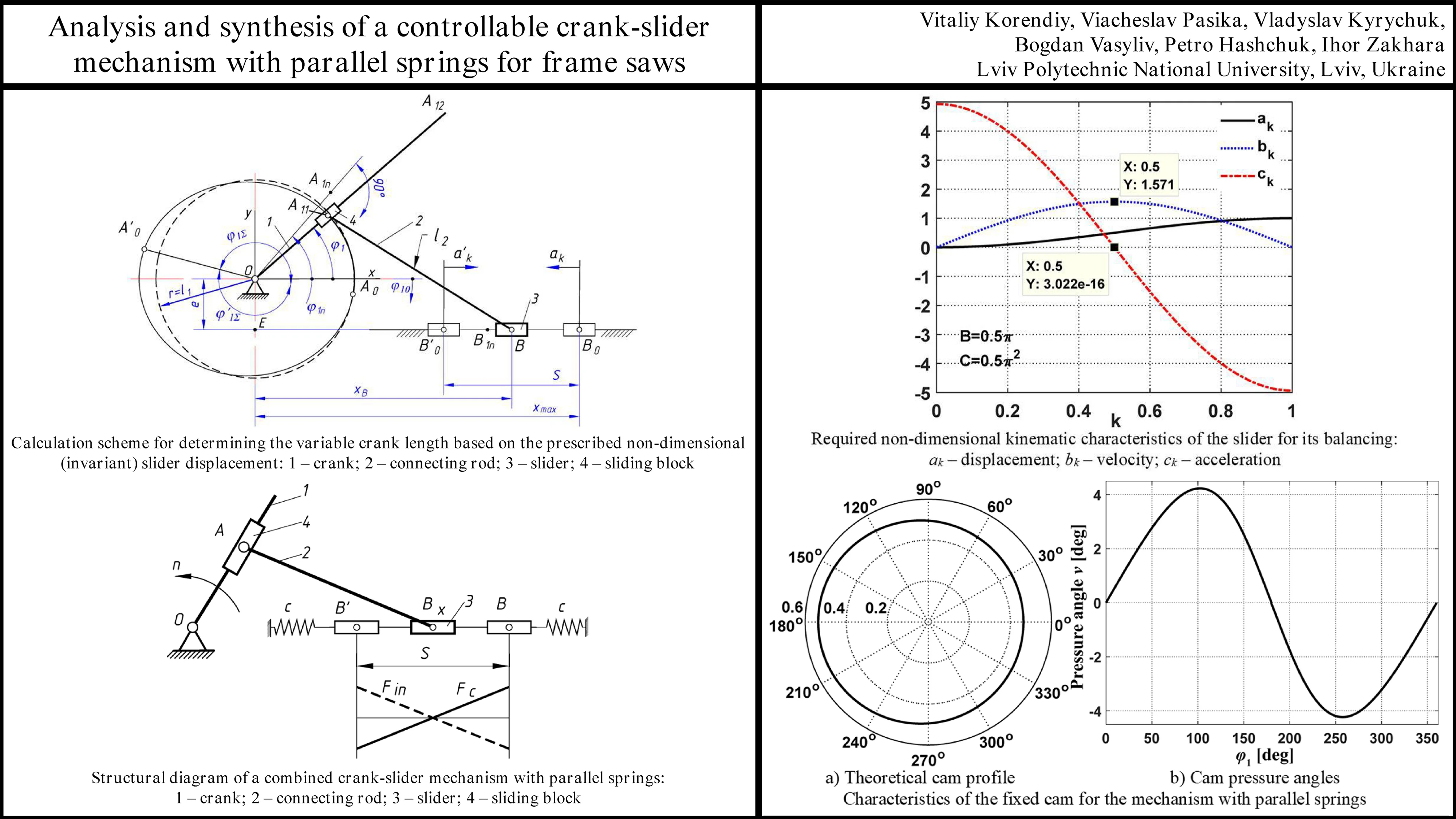
The structural diagram of the mechanism under study is shown in Fig. 1. We denote the initial crank length in the extreme right position of the slider as , the variable crank length as , the initial connecting rod length as , the eccentricity as , the slider coordinates in the coordinate system as , , and the slider stroke as . In non-dimensional (invariant) form, relative to the slider stroke (often normalized to ), we have: , , , , , . We define the law of motion using the non-dimensional (invariant) displacement for the slider motion towards the crank rotation center, and for the motion away from the center. The normalization of the mechanism’s geometric dimensions relative to the stroke is chosen deliberately, since in the kinematic synthesis of crank-slider mechanisms, , , and the maximal dimension ratio, e.g. , are typically specified. Using these parameters, the initial lengths of the crank and connecting rod will be calculated using the following relationships:
We can synthesize the variable crank length by solving the following mathematical problem: determining the intersection points between a line passing through the crank rotation center (O) and a circle of radius (the length of the connecting rod AB) centered at point B (Fig. 1).
Let us represent the line in parametric form and write a system of equations for the coordinates of the intersection points. For clarity, all derivations will be carried out using dimensional quantities. Then, the system of equations is as follows:
where , are the coordinates of the intersection points and ; is the variable crank length.
Fig. 1Calculation scheme for determining the variable crank length based on the prescribed non-dimensional (invariant) slider displacement: 1 – crank; 2 – connecting rod; 3 – slider; 4 – sliding block
Substituting the expressions for and into the third equation of the Eq. (2) and performing straightforward transformations yields a quadratic equation for the variable crank length:
where ; ; and are the crank rotation angles for slider displacements of the same sign.
The roots of this equation are as follows:
As the crank rotation angle increases, the distance between points and decreases, and at some angle , these points coincide at point , and the line becomes tangent to the circle. This tangency condition determines the necessary length of the connecting rod that ensures the slider moves according to the prescribed law for the chosen geometric dimensions of the mechanism. Let us denote this length as and determine it from the condition or . In the expanded form, this condition is as follows:
It is most practical to determine the value of the angle , for which the condition defining the minimum of the function occurs, using numerical methods, since an analytical determination would still necessitate solving a nonlinear transcendental equation numerically.
Let us plot the function and determine the angle at which the function attains its minimum. Next, using Eq. (5), let us calculate the synthesized value of the connecting rod length:
Analysis of the obtained results shows that of the two real roots Eq. (4), for , the first root is valid, while for , the second root is valid. When the crank and connecting rod are mutually perpendicular, the crank radius is calculated using the obvious expression:
where .
Using the sign function, we obtain an expression for calculating the variable crank length that is valid for any crank rotation angle:
where , for ; for ; for ; is the required non-dimensional (invariant) law of motion of the slider.
In the non-dimensional (invariant) form, the non-dimensional crank length is determined as follows:
where is a new non-dimensional variable; ; is the crank angle range during the slider displacement towards the crank rotation center and at ; is the crank angle range during the displacement away from the rotation center and at .
The crank angle range is calculated using the following expressions:
Thus, the variable crank length, which provides the dynamic balancing of a crank-slider mechanism and ensures inertia-free motion of a slider (saw frame), can be calculated using Eqs. (8) or (9). Although the slider experiences variable velocity and acceleration, the inertia forces are fully balanced by the elastic forces of the parallel springs, which have the same functional dependence on displacement.
2.2. Synthesis of the variable crank length in the combined crank-slider mechanism with parallel spring placement
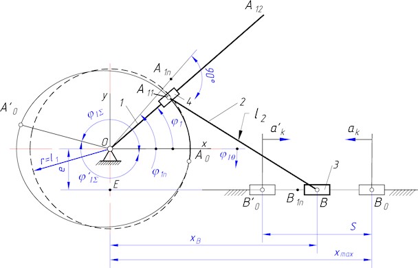
With parallelly positioned springs (Fig. 2), the elastic force acting on the slider varies according to a linear law and is , where is the spring stiffness, is the spring deformation, and is the non-dimensional slider displacement. To balance the slider, the slider’s law of motion must follow a cosine law, whose non-dimensional form is . In this case, the relationship between the slider’s acceleration and its displacement is also linear. Indeed, the non-dimensional acceleration is and , which expresses a linear relationship. The inertia force of the slider is calculated using the obvious expression , where is the unbalanced mass of the slider, and is the time for unidirectional slider displacement. For slider balancing, the inertia forces and the elastic forces of the springs must be equal in magnitude. Then, from the equality of these forces at the extreme position (if , ), let us calculate the required spring stiffness for balancing the slider with parallel springs:
where is the non-dimensional (invariant) stiffness for parallel springs.
Fig. 2Structural diagram of a combined crank-slider mechanism with parallel springs: 1 – crank; 2 – connecting rod; 3 – slider; 4 – sliding block
The cosine periodic law of motion of the considered crank-slider mechanism with parallel springs is shown in Fig. 2. Next, using Eqs. (6) or (7), one can calculate the variable crank length (the theoretical radius vector of the fixed cam profile).
3. Results and discussion
3.1. Results of numerical modeling
For the numerical analysis, the following dimensions of a frame saw were used: saw frame stroke 0.6 m, connecting rod length 2 m, and eccentricity 0 m. The number of spring pairs is set to and the coefficient .
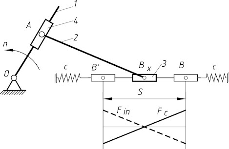
Fig. 3 shows the required non-dimensional (invariant) kinematic characteristics for the slider that ensure it is balanced. In the case of parallelly positioned springs, these are the invariants of the cosine periodic law of motion. The maximum acceleration is characterized by the peak acceleration constant , and the maximum velocity – by the peak velocity constant 1.57.
Fig. 4 shows the theoretical cam profile (variable crank length) and its pressure angles for the mechanism with parallelly positioned springs. In the synthesized mechanism, the connecting rod length also changed from to . The synthesized profile is very similar to a circle whose center is offset to the left (Fig. 4(a)). Calculations showed that when the profile is shifted to the right by 0.03747, the horizontal diameter of the circle would , and the vertical diameter . Here, the average diameter differs by 0.5% from a circle with diameter . This fact is a positive aspect, since the manufacturing of the cam could possibly be simplified to constructing a circular disc that rotates about an axis offset by 0.03747 from its geometric axis. However, this can only be confirmed after conducting an analysis of such a mechanism. The pressure angles of the synthesized profile do not exceed 4.2° (Fig. 4(b)) and are much smaller than the permissible angle for cam mechanisms with translating followers (40°...50°).
Fig. 3Required non-dimensional kinematic characteristics of the slider for its balancing: ak – displacement; bk – velocity; ck – acceleration
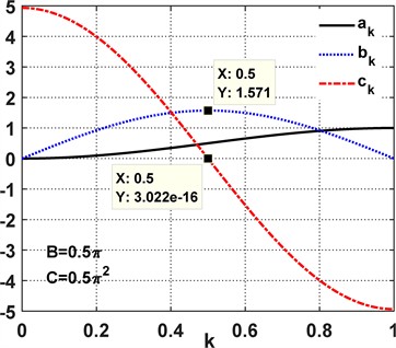
Fig. 4Characteristics of the fixed cam for the mechanism with parallel springs
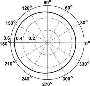
a) Theoretical cam profile
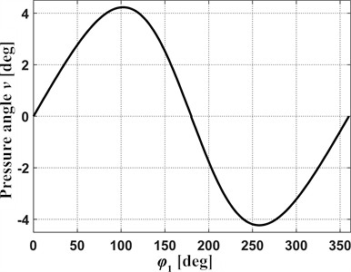
b) Cam pressure angles
4. Discussion of the results obtained
The results demonstrate the successful synthesis of the proposed mechanism with parallel springs, achieving the primary goal of deriving such a configuration that theoretically eliminates net dynamic forces on the slider. It was shown that a simpler cosine law of motion achieves a balance due to the linear nature of both the resulting inertia force and the parallel spring force . Based on these synthesized motion laws, the required variable crank length functions (equivalent to the theoretical cam profile ) were determined using the derived analytical Eq. (8) or (9). Furthermore, the necessary geometric parameters for implementation, specifically the minimum required connecting rod length ( or ) and the required spring stiffness ( or ), were calculated based on the tangency condition and force balance at extreme positions, respectively. Crucially, the analysis of the pressure angles associated with the synthesized cam profile indicated that they remain within permissible limits (less than 4.5°), suggesting the feasibility of such a design from a cam-follower interaction perspective.
The proposed synthesis methodology offers a distinct alternative to conventional approaches for mitigating inertial forces in reciprocating machines. While methods like adding counterweights [8-10], utilizing specifically designed balancing cams [24-27], employing planetary mechanisms [16-19], or leveraging resonance exist [13, 14], the approach here focuses on tailoring the fundamental kinematics of the main drive itself. By defining a desired output motion law that results in force cancellation and then synthesizing the input mechanism (variable crank length or cam profile ) required to produce it, this work embodies a direct kinematic synthesis approach to dynamic balancing. This is particularly relevant for frame saws where the large reciprocating mass of the saw frame is the primary source of vibration and dynamic load. The variable-length crank mechanism, actuated by a cam, functions as a form of programmable crank, allowing the generation of complex motion profiles beyond what a standard crank-slider can produce, akin to capabilities found in more complex cam-linkage or controllable crank systems.
The practical implementation hinges on the manufacturability of the required variable crank length mechanism, primarily the fixed cam profile. For the mechanism with parallel springs, the synthesized cam profile was found to be nearly circular, differing from a true circle by less than 0.5 % in average diameter (based on calculated horizontal and vertical extents). This suggests the possibility of realizing this mechanism using a simple eccentric circular cam, allowing for a significant simplification compared to manufacturing a complex non-circular profile. This finding substantially enhances the practical potential of the parallel spring configuration, although further analysis of the dynamic performance with an actual eccentric circular cam is warranted.
It should be emphasized that the calculated stiffness of the springs was derived exclusively from the condition of equilibrium between the inertia forces of the reciprocating slider and the restoring forces of the parallel springs. This approach ensures that the primary source of dynamic loading – the inertial action of the saw frame – is effectively compensated. Cutting forces, although present in real sawing processes, are significantly smaller in magnitude compared to the inertia forces at the operating speeds under consideration [1, 6, 7]. Therefore, their influence on the determination of spring stiffness was neglected in the present study. Nevertheless, for a more comprehensive dynamic model of the mechanism, the effect of cutting forces on the overall balance will be analyzed in future research.
5. Conclusions
This paper successfully addressed the objective of synthesizing dynamically balanced drive mechanisms for frame saws by employing a novel crank-slider mechanism with a cam-actuated variable-length crank. For the mechanism with parallel springs, the balancing was achieved using a cosine law of motion , which linearly relates slider acceleration to displacement, matching the linear characteristic of the parallel springs. The required theoretical cam profile, calculated via Eq. (9), was found to be nearly circular, with horizontal and vertical diameters differing minimally (, in non-dimensional terms) and the average diameter differing by less than 0.5 % from a perfect circle . This suggests a high potential for simplification using an eccentric circular cam. The required non-dimensional connecting rod length was 3.3698, and the pressure angles were very low (below 4.2°).
The proposed synthesis methodology allows for the design of frame saw mechanisms where the primary inertia loads are theoretically eliminated, achieved through specific slider motion laws generated by a variable-length crank mechanism. The parallel spring configuration offers the significant practical advantage of potentially being realized with a simple eccentric circular cam. These findings pave the way for frame saws capable of higher operating speeds, reduced vibration, lighter construction, and improved overall performance.
Future research will focus on detailed dynamic simulations of the synthesized mechanisms, incorporating friction, component elasticity, and cutting loads, followed by the development and experimental testing of physical prototypes to validate the theoretical balancing effectiveness and performance benefits in real-world conditions. Analysis of the simplified eccentric circular cam implementation is also a key next step.
References
-
C. Gottlöber, “Cutting and disintegration of wood and wood-based materials,” in Springer Handbook of Wood Science and Technology, Cham: Springer International Publishing, 2023, pp. 595–677, https://doi.org/10.1007/978-3-030-81315-4_12
-
Y.-T. Chen, J.-H. Tian, X.-L. Guo, and B. Na, “Tool condition monitoring strategies from metal cutting: insights for optimizing wood-based material processing,” European Journal of Wood and Wood Products, Vol. 83, No. 1, p. 46, Jan. 2025, https://doi.org/10.1007/s00107-024-02198-5
-
P. Dong, J. Zhang, and H. Zhang, “Wear performance of diamond tools during sawing with reciprocating swing frame saw,” Diamond and Related Materials, Vol. 143, p. 110890, Mar. 2024, https://doi.org/10.1016/j.diamond.2024.110890
-
L. Dziuba, M. Pylypchuk, O. Chmyr, and R. Pavliuk, “Model of parametric reliability of woodworking machine tools,” Journal of Engineering Sciences, Vol. 12, No. 1, pp. A12–A19, Jan. 2025, https://doi.org/10.21272/jes.2025.12(1).a2
-
D. H. Minh, P. van Binh, and N. V. Duc, “Multi-objective optimization of saw blade module in a new type of frame saw machine using the parameter space investigation method,” in Mechanisms and Machine Science, Cham: Springer Nature Switzerland, 2025, pp. 85–95, https://doi.org/10.1007/978-3-031-83357-1_9
-
Z. Hao, F. Zhang, X. Li, Y. Wang, T. Zhang, and X. Guo, “Optimization of oak sawing parameters based on energy consumption and surface roughness,” Materialwissenschaft und Werkstofftechnik, Vol. 55, No. 10, pp. 1346–1356, Oct. 2024, https://doi.org/10.1002/mawe.202300385
-
D. Chuchala, K. A. Orlowski, G. Sinn, and A. Konopka, “Comparison of the fracture toughness of pine wood determined on the basis of orthogonal linear cutting and frame sawing,” Acta Facultatis Xylologiae Zvolen, Vol. 63, No. 1, pp. 75–83, Jan. 2021, https://doi.org/10.17423/afx.2021.63.1.07
-
H. Schneegans, J. J. de Jong, F. Cosandier, and S. Henein, “Mechanism Balancing Taxonomy,” Mechanism and Machine Theory, Vol. 191, p. 105518, Jan. 2024, https://doi.org/10.1016/j.mechmachtheory.2023.105518
-
J. Gallardo-Alvarado, “A simple matrix method for the force balancing of planar multi-degree-of-freedom linkages,” International Journal of Mechanical Engineering Education, Vol. 53, No. 3, pp. 691–719, May 2024, https://doi.org/10.1177/03064190241255639
-
P. Flückiger, F. Cosandier, H. Schneegans, and S. Henein, “Design of a flexure-based flywheel for the storage of angular momentum and kinetic energy,” Machines, Vol. 12, No. 4, p. 232, Mar. 2024, https://doi.org/10.3390/machines12040232
-
O. Lanets, O. Kachur, V. Korendiy, and V. Lozynskyy, “Controllable crank mechanism for exciting oscillations of vibratory equipment,” in Lecture Notes in Mechanical Engineering, Cham: Springer International Publishing, 2021, pp. 43–52, https://doi.org/10.1007/978-3-030-77823-1_5
-
V. Korendiy, O. Lanets, O. Kachur, P. Dmyterko, and R. Kachmar, “Determination of inertia-stiffness parameters and motion modelling of three-mass vibratory system with crank excitation mechanism,” Vibroengineering Procedia, Vol. 36, pp. 7–12, Mar. 2021, https://doi.org/10.21595/vp.2021.21924
-
W. Fiebig and W. Prastiyo, “Utilization of mechanical resonance for the enhancement of slider-crank mechanism dynamics in gas compression processes,” Energies, Vol. 15, No. 20, p. 7769, Oct. 2022, https://doi.org/10.3390/en15207769
-
W. Fiebig and W. Prastiyo, “An innovative method of utilization of mechanical resonance for the reduction of dynamical loads in the reciprocating compressors,” in Proceedings of the 29th International Congress on Sound and Vibration, ICSV 2023, 2023.
-
V. Arakelian, “Reduction of input torque and joint reactions in high-speed mechanical systems with reciprocating motion,” WSEAS Transactions on Applied and Theoretical Mechanics, Vol. 19, pp. 88–96, Jul. 2024, https://doi.org/10.37394/232011.2024.19.10
-
L. Li, C. Dong, and Y. Liu, “Optimization design of noncircular gear planetary gear system based on noncircular beveloid gear,” Measurement, Vol. 248, p. 116952, May 2025, https://doi.org/10.1016/j.measurement.2025.116952
-
A. A. Prikhodko, “Kinetostatics of rotationally reciprocating stirred tank planetary actuator,” in Lecture Notes in Mechanical Engineering, Cham: Springer International Publishing, 2019, pp. 359–366, https://doi.org/10.1007/978-3-030-22041-9_40
-
A. A. Prikhodko, “Force analysis of the two-satellite planetary mechanism with elliptical gears,” Mechanics and Mechanical Engineering, Vol. 25, No. 1, pp. 39–46, Jan. 2021, https://doi.org/10.2478/mme-2021-0006
-
Y. Hu, G. Zhao, X. Du, C. Ma, L. Tuo, and Z. Chu, “Study on the dynamic characteristics of planetary gear transmission mechanism of metal cold rolling mill,” Mechanics and Industry, Vol. 25, No. 20, p. 20, Jun. 2024, https://doi.org/10.1051/meca/2024014
-
V. Korendiy, O. Parashchyn, V. Heletiy, V. Pasika, V. Gurey, and N. Maherus, “Kinematic analysis and geometrical parameters justification of a planetary-type mechanism for actuating an inertial vibration exciter,” Vibroengineering Procedia, Vol. 52, pp. 35–41, Nov. 2023, https://doi.org/10.21595/vp.2023.23728
-
V. Korendiy, V. Gurey, V. Borovets, O. Kotsiumbas, and V. Lozynskyy, “Generating various motion paths of single-mass vibratory system equipped with symmetric planetary-type vibration exciter,” Vibroengineering Procedia, Vol. 43, pp. 7–13, Jun. 2022, https://doi.org/10.21595/vp.2022.22703
-
J. Buśkiewicz, “Balancing of a wire rope hoist using a cam mechanism,” in Lecture Notes in Mechanical Engineering, Cham: Springer International Publishing, 2019, pp. 25–35, https://doi.org/10.1007/978-3-030-16943-5_3
-
G. L. H. Johnston, A. L. Orekhov, and N. Simaan, “Design considerations and robustness to parameter uncertainty in wire-wrapped cam mechanisms,” Journal of Mechanisms and Robotics, Vol. 16, No. 2, Feb. 2024, https://doi.org/10.1115/1.4056600
-
D.-Y. Lin, B.-J. Hou, and C.-C. Lan, “A balancing cam mechanism for minimizing the torque fluctuation of engine camshafts,” Mechanism and Machine Theory, Vol. 108, pp. 160–175, Feb. 2017, https://doi.org/10.1016/j.mechmachtheory.2016.10.023
-
M. Václavík, P. Jirásko, and J. Bělík, “Triple cam mechanism for compensating drive torque,” Mechanisms and Machine Science, Vol. 149, pp. 230–240, Nov. 2023, https://doi.org/10.1007/978-3-031-45709-8_23
-
W.-T. Chang and Y.-E. Hu, “An integrally formed design for the rotational balancing of disk cams,” Mechanism and Machine Theory, Vol. 161, p. 104282, Jul. 2021, https://doi.org/10.1016/j.mechmachtheory.2021.104282
-
W.-T. Chang, Y.-E. Hu, and W.-C. Chang, “An improved design for rotating balance of assembled type conjugate disk cams,” Mechanism and Machine Theory, Vol. 171, p. 104700, May 2022, https://doi.org/10.1016/j.mechmachtheory.2021.104700
-
T. T. N. Nguyen, T. X. Duong, and V.-S. Nguyen, “Design general cam profiles based on finite element method,” Applied Sciences, Vol. 11, No. 13, p. 6052, Jun. 2021, https://doi.org/10.3390/app11136052
-
Nguyen and Thi Thanh Nga, “Computational optimization of cam knife-edge follower design using potential energy analysis,” Mathematical Modelling of Engineering Problems, Vol. 10, No. 3, pp. 774–780, Jun. 2023, https://doi.org/10.18280/mmep.100306
-
V. Pasika, P. Nosko, O. Nosko, O. Bashta, V. Heletiy, and V. Melnyk, “A method to synthesise groove cam Geneva mechanisms with increased dwell period,” Proceedings of the Institution of Mechanical Engineers, Part C: Journal of Mechanical Engineering Science, Vol. 238, No. 15, pp. 7544–7555, Feb. 2024, https://doi.org/10.1177/09544062241234477
About this article

The authors have not disclosed any funding.
The datasets generated during and/or analyzed during the current study are available from the corresponding author on reasonable request.
