Abstract
The article presents a mathematical model of the oscillation system of a resonant vibration stand with an eccentric-pendulum drive. The principle of operation of this stand is as follows. A shaft is installed in the body of the reactive body, on which a pendulum is placed with eccentricity. The shaft is driven by an asynchronous electric motor through a flexible coupling. The pendulum and the reactive body are periodically displaced relative to each other by the amount of eccentricity due to the rotation of the shaft. The working (active) body is disturbed by the movement of the reactive body. The article outlines the advantages of machines of this type in comparison with the most common types. A mathematical model is compiled in the form of seven second-order differential equations. The parameters of the mechanical oscillation system and drive are given. The operation of the oscillation system of the resonant vibration stand is simulated. As a result of mathematical modeling, it was established that this model of the vibration stand is promising for implementation in industry.
Highlights
- The developed and analyzed mathematical model of the eccentric-pendulum type vibrating table in transient and steady-state operating modes indicates that the design is operational. Analysis of the motion of the oscillating masses confirms the correctness of the parameters set.
- Thanks to the use of a pendulum, it is possible to minimize the amplitudes of vibrations of the vibration stand in the horizontal direction.
- The implementation of a working body driven by a kinematically perturbed reactive body enabled a 2.5-fold increase in the vertical vibration amplitudes compared to the previous design.
1. Introduction
Specialized stands are widely used for vibration testing of aviation industry products. Such vibration stands are used to establish the natural frequencies of the structure under study or for long-term vibration resistance testing. The first type of stands provides a wide range of changes in the frequency of forced oscillations [1], the second type mainly operates at a clearly established frequency. The object of study of this article is the second type of vibration stands, operating at a clearly established frequency of forced oscillations. Such stands have much in common with vibration technological equipment.
Resonant designs of vibration tables (stands) are known, which provide amplification of vibrations in the vertical direction, but do not prevent lateral and angular perturbation of the working body [2]. To prevent this, two vibrator motors are used in industry, rotating towards each other [3]-[5]. More complex inertial drive designs are also used [6], [7]. But this further complicates the two-mass design. It is more expedient to implement a structurally simpler resonant vibrating table with an unbalanced drive [5]. It uses paired vibrator motors, the vibration exciters of which rotate towards each other, allowing only the vertical component of the disturbance. However, in such a design, a change in the load mass and a change in its location on the surface of the vibrating table can cause undesirable transient processes, during which lateral and angular vibrations will occur due to a violation of the self-synchronization of the two vibration exciters.
Vibration machines with an electromagnetic drive are also used as technological equipment. However, the highly efficient designs [8], [9] of such vibration machines have a number of disadvantages, in particular those related to the stability of functioning in the interresonant oscillation mode.
There are vibration drives with an eccentric-pendulum drive [10] and crank-type exciters [11, 12]. Such machines are partially devoid of the disadvantages of vibration machines with an unbalanced drive. They reach the nominal operating modes from a state of rest in a short period of time and rapidly stop. Structurally, the vertical directional movement of the working body is simply implemented. Working near such vibrating equipment is much safer. However, such equipment is non-resonant.
The authors of the article will demonstrate an attempt to implement a model of a resonant vibration stand using an eccentric-pendulum drive. It is assumed to use only one electric motor and the absence of mechanisms for forced direction of oscillations.
2. Description of the schematic diagram and dynamic model of a resonant vibration stand with an eccentric-pendulum drive
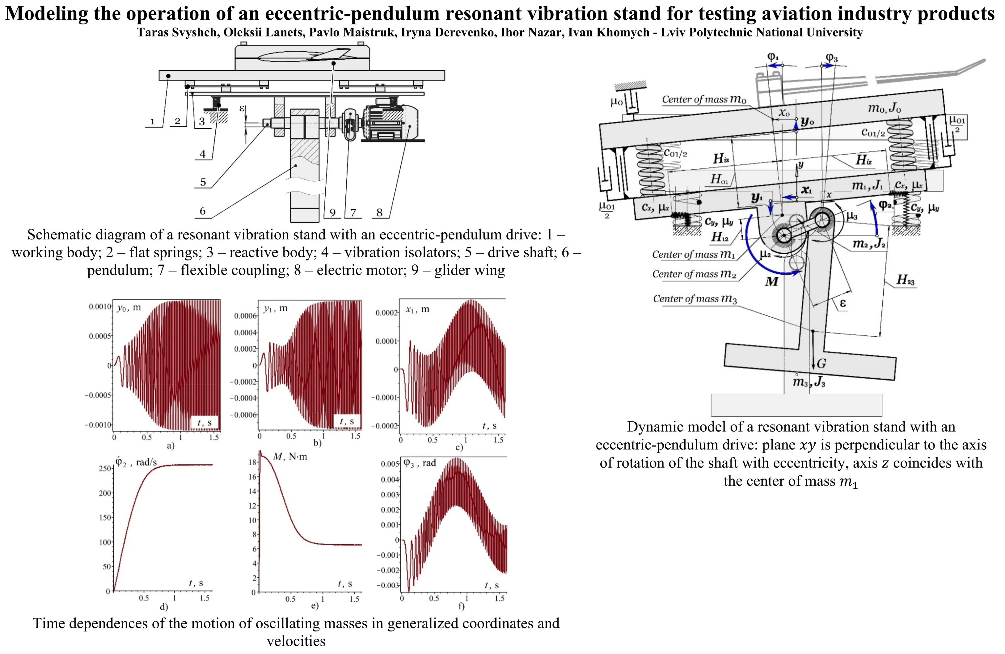
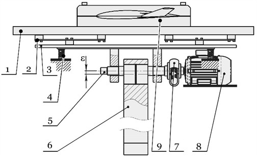
Fig. 1 shows a schematic diagram of the proposed eccentric-pendulum type vibration stand. The working body 1 is connected to the reactive body 3 through resonant elastic elements 2, which are mounted on the foundation through vibration isolators 4 (elements with a low stiffness coefficient in the vertical direction). The drive shaft 5 is installed in the housing of the reactive body 3, on which the pendulum 6 is mounted with eccentricity . The shaft 5 is driven by an asynchronous electric motor 8 through a flexible coupling 7. The pendulum 6 and the reactive body 3 are periodically displaced relative to each other by an amount due to the rotation of the shaft 5. The working (active) body 1 is disturbed by the movement of the reactive body 3. The glider wing 9 is rigidly cantilevered to the working body. This stand is being developed precisely to study the vibration resistance of the glider wing.
Fig. 1Schematic diagram of a resonant vibration stand with an eccentric-pendulum drive: 1 – working body; 2 – flat springs; 3 – reactive body; 4 – vibration isolators; 5 – drive shaft; 6 – pendulum; 7 – flexible coupling; 8 – electric motor; 9 – glider wing
Consider a flat model of a vibration stand (Fig. 2). Establish a basic coordinate system , the plane of which is perpendicular to the axis of rotation of the shaft with eccentricity, and the axis is directed vertically. The axis coincides with the center of mass . The oscillatory system consists of four absolutely rigid bodies: a working body with a mass (taking into account the load) with a moment of inertia about the axis passing through its center of mass perpendicular to the plane; a reactive body with a mass with a moment of inertia ; an eccentric shaft with a mass with a moment of inertia about the axis of rotation and a pendulum with a mass with a moment of inertia about the axis passing through its center of mass perpendicular to the plane . The parameter takes into account the moment of inertia of the rotor of the electric motor, in contrast to the parameter , which does not take into account the mass of the rotor. This is related to the fact that, due to the use of a lobe clutch, a mechanical decoupling is established between the shaft and the electric motor along the axes and . According to this, the oscillatory motion of the reactive body has practically no effect on the rotor of the electric motor. The working body is connected by mass to the reactive body by mass through resonant elastic elements with stiffness coefficient along the axis . It is assumed that the mass rotates together with the mass .
Fig. 2Dynamic model of a resonant vibration stand with an eccentric-pendulum drive: plane xy is perpendicular to the axis of rotation of the shaft with eccentricity, axis z coincides with the center of mass m1
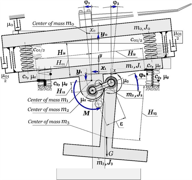
The motion of the system can be described using the following independent coordinates: oscillation of the mass along the axis by the generalized coordinate ; oscillation of the mass along the axes , and around its own center of mass in the plane by the generalized coordinates , and ; rotational motion of the masses and around their own centers of mass in the plane by the generalized coordinates and . Furthermore, we additionally consider the moment of disturbance of the electric motor as a generalized coordinate. Therefore, the oscillatory system has seven degrees of freedom.
The distance from the center of mass to the center of mass is denoted by . The distance from the center of mass to the shaft axis is denoted by , and from the shaft to the center of mass – . The horizontal distance from the vibration isolators to the center of mass of the reactive body is denoted by . The vibration system is mounted on a fixed base through vibration isolators attached from below to the reactive body, and their stiffness coefficients along the axes and are respectively and . To take into account the effect of the load on the working body, the viscous resistance coefficient is introduced . The coefficients and determine the energy dissipation in the vibration isolators during the movement of the mass along the axes, respectively, and . The coefficient reflects the viscous friction in the bearings between the reactive body and the shaft (between the masses and ), and between the shaft and the pendulum (between the masses and ). The dynamic effect of the cantilevered wing on the working body is not considered in this study.
The linear and angular coordinates for each of the masses , , and can be written as follows. By deviating the center of mass from the equilibrium position , its generalized coordinates along the axes and are written as and (Fig. 2). The working body (mass ) moves along the axis along the generalized coordinate . The angular deviation of the mass and mass from its own center of mass is determined by the angular coordinate . The angular deviations of the masses and around their own centers of mass are determined by the angular coordinates respectively and .
The remaining linear coordinates of the centers of mass , and are dependent and are determined through generalized coordinates as follows: ; .
Therefore, there are 12 coordinates that completely describe the motion of the four oscillating masses in the plane. Since the angular oscillations of the jet body (mass ) and the pendulum (mass ) around their own centers of mass are small, to simplify further calculations we will use the following approximations: , , which are valid for small values of . The system of differential equations of motion of oscillating masses in seven generalized coordinates is formed using generalized Lagrange equations of the second-order. Taking into account the equation of an asynchronous electric motor [13] the system of equations has the form:
The values of the parameters of the oscillatory system included in the developed mathematical model are as follows: N/m; N/m; m; m/s2; m; m; m; m; kg∙m2; kg∙m2; kg∙m2; kg∙m2; kg; kg; kg; kg; N∙m/s; N∙m/s; N∙m∙s/rad; N∙m∙s/rad. In addition, the maximum torque in the electric motor is = 18.7 N∙m; the electromagnetic time constant of the electric motor 0.074; the synchronous angular speed of rotation of the rotor of the electric motor is rad/s. The model of the electric motor – 4A90L2Y3, with the power of 3 kW.
3. Results of mathematical modeling of the operation of a vibration stand with an eccentric-pendulum drive
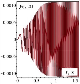
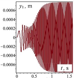
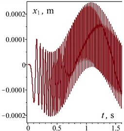
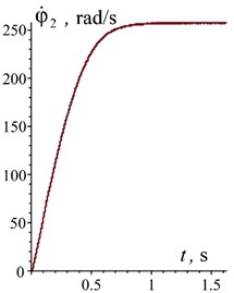
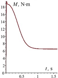
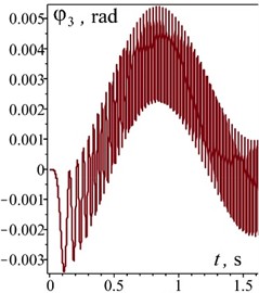
The above data are sufficient to solve the system numerically. The system Eq. (1) was solved using the Rosenbrock numerical method in the Maple software. The initial conditions for the values of the generalized coordinates and their velocities are equal to zero. Of greatest interest are the transient modes of operation of the vibration stand. For this purpose, the time is limited to the first 1,5 seconds. The obtained dependences of the system motion on generalized coordinates and velocities are shown in Fig. 3.
Fig. 3Time dependences of the motion of oscillating masses in generalized coordinates and velocities
a)
b)
c)
d)
e)
f)
The obtained dependences indicate that the oscillatory system reaches a steady state (the electric motor reaches its rated speed) in approximately 1 s without significant dynamic overloads. This is clearly seen in the characteristics of the disturbing moment in the electric motor (Fig. 3(e)), the characteristics of the rotor speed of the electric motor (Fig. 3(d)), and the characteristics of the oscillatory motion of the reactive body (Fig. 3(b)). The established oscillations of the working body along the vertical axis are 1.1 mm (Fig. 3(a)) at the angular velocity of the rotor of the electric motor 260 rad/s (Fig. 3(d)). In this case, the overload on the working body is 7.6. This meets the necessary technical requirements for the vibration stand. The oscillations of the reactive body along the horizontal axis at the frequency of forced oscillations are 0.11 mm (Fig. 3(c)). The horizontal amplitude of oscillations for the working body is practically the same. The pendulum performs oscillatory motion around the shaft axis with a period of 1.5 s (Fig. 3(f)).
4. Conclusions
The developed and analyzed mathematical model of the eccentric-pendulum type vibrating table in transient and steady-state operating modes indicates that the design is operational. Analysis of the motion of the oscillating masses confirms the correctness of the parameters set.
Thanks to the use of a pendulum, it is possible to minimize the amplitudes of vibrations of the vibration stand in the horizontal direction. Thanks to the use of a working body, which is driven by a reactive body (kinematically perturbed), it was possible to increase the amplitudes of mass vibrations in the vertical direction by 2.5 times compared to the design [10].
References
-
M. Böswald and Y. Govers, “Taxi vibration testing – an alternative method to ground vibration testing of large aircraft,” in International Conference on Noise and Vibration Engineering, pp. 2413–2426, 2008.
-
N. Yaroshevich, O. Yaroshevych, and V. Lyshuk, “Drive dynamics of vibratory machines with inertia excitation,” in Mechanisms and Machine Science, Cham: Springer International Publishing, 2021, pp. 37–47, https://doi.org/10.1007/978-3-030-60694-7_2
-
Z. V. Despotovic, A. M. Pavlovic, and D. Ivanic, “Exciting force frequency control of unbalanced vibratory actuators,” in 20th International Symposium on Power Electronics (Ee), pp. 1–6, Oct. 2019, https://doi.org/10.1109/pee.2019.8923574
-
G. Cieplok and K. Wójcik, “Conditions for self-synchronization of inertial vibrators of vibratory conveyors in general motion,” Journal of Theoretical and Applied Mechanics, Vol. 58, No. 2, pp. 513–524, Apr. 2020, https://doi.org/10.15632/jtam-pl/119023
-
O. Lanets, Fundamentals of Analysis and Design of Vibratory Machines. (in Ukrainian), Lviv, Ukraine: Lviv Polytechnic Publishing House, 2018.
-
V. Gursky, P. Krot, V. Korendiy, and R. Zimroz, “Dynamic analysis of an enhanced multi-frequency inertial exciter for industrial vibrating machines,” Machines, Vol. 10, No. 2, p. 130, Feb. 2022, https://doi.org/10.3390/machines10020130
-
V. Gursky, I. Kuzio, P. Krot, and R. Zimroz, “Energy-saving inertial drive for dual-frequency excitation of vibrating machines,” Energies, Vol. 14, No. 1, p. 71, Dec. 2020, https://doi.org/10.3390/en14010071
-
P. Maistruk, O. Lanets, V. Maistruk, and I. Derevenko, “Establishment of the natural frequency of oscillations of the two-dimensional continuous member of the vibrating table,” Journal of Theoretical and Applied Mechanics, Vol. 52, No. 3, pp. 199–214, Aug. 2022, https://doi.org/10.55787/jtams.22.52.3.199
-
P. Maistruk, O. Lanets, and V. Maistruk, “Determining the influence of continuous section shape and dimensions on stresses over a wide range of vibration frequency,” Ukrainian Journal of Mechanical Engineering and Materials Science, Vol. 10, No. 4, pp. 54–69, Jan. 2024, https://doi.org/10.23939/ujmems2024.04.054
-
O. S. Lanets, V. T. Dmytriv, V. M. Borovets, I. A. Derevenko, and I. M. Horodetskyy, “Analytical model of the two-mass above resonance system of the eccentric-pendulum type vibration table,” International Journal of Applied Mechanics and Engineering, Vol. 25, No. 4, pp. 116–129, Dec. 2020, https://doi.org/10.2478/ijame-2020-0053
-
V. Korendiy, O. Lanets, O. Kachur, P. Dmyterko, and R. Kachmar, “Determination of inertia-stiffness parameters and motion modelling of three-mass vibratory system with crank excitation mechanism,” Vibroengineering Procedia, Vol. 36, pp. 7–12, Mar. 2021, https://doi.org/10.21595/vp.2021.21924
-
O. Kachur and V. Korendiy, “Dynamic behavior of vibratory screening conveyor equipped with crank-type exciter,” in Lecture Notes in Mechanical Engineering, Cham: Springer Nature Switzerland, 2023, pp. 44–53, https://doi.org/10.1007/978-3-031-32774-2_5
-
W. Wenske, “On the derivation of the dynamic characteristic of the asynchronous motor with regard to the calculation of vibration phenomena in propulsion systems,” (in German), Scientific Journal of the O. Guericke University of Technology, Vol. 14, No. 5/6, pp. 517–523, 1970.
About this article

The authors have not disclosed any funding.
The datasets generated during and/or analyzed during the current study are available from the corresponding author on reasonable request.
