Abstract
The article presents a mathematical model of a resonant two-mass vibration stand with an inertial exciter, driven by an asynchronous electric motor through a hydraulic coupling. The necessary parameters of the mechanical vibration system and drive are substantiated. The design feature of the vibration stand is as follows: the drive shaft of the hydraulic coupling is driven by an electric motor, and the driven shaft of the hydraulic coupling is connected to the unbalanced mass. The work simulates a vibration stand. As a result of mathematical modeling, it was established that the rotor of the electric motor reaches the nominal operating modes, and the unbalanced mass speed “hangs” in the vicinity of the resonant peak due to processes associated with the Sommerfeld effect. This allowed for the automatic “fixing” of the frequency of forced oscillations with close pre-resonance tuning, providing energy-saving operating modes in the vibration stand. Expensive control systems are not required.
Highlights
- The article confirms that, provided that the oscillation system is driven by asynchronous electric motors through hydraulic couplings, it is possible to ensure stable operation of vibration technological equipment in a near-resonant operating mode.
- The mathematical model reproduced the effect of “hanging” (Sommerfeld effect) of unbalanced mass rotations in the vicinity of the system’s natural oscillation frequency.
- The possibility of creating energy-saving designs implemented using resonant operating modes was confirmed using the example of a two-mass vibration stand with an inertial drive.
1. Introduction
Testing of aviation products is essential in ensuring their reliability during operation. Vibration testing is an integral part of probation [1], [2]. In industry, two-mass vibration machines with unbalanced vibration exciters have become widespread, the operating mode of which is pre-resonant relative to the natural frequency of oscillations of the system [3]. This mode allows for a significant reduction in the power consumption of the drive. In such vibration machines, to stabilize the unbalanced rotation frequency in the vicinity of the resonant peak, control systems [4] or complex inertial drive systems [5], [6] are used, which increase the cost of the structures and their maintenance.
In the scientific work [7], an attempt was made to synthesize a resonant unbalanced vibrating table driven by a DC electric motor. The control system was not used due to the fact that as the angular velocity of the electric motor rotor approached the resonant peak of the system, the unbalanced mass revolutions “hang” in the vicinity of the resonant one due to processes associated with the Sommerfeld phenomenon. This made it possible to “fix” the frequency of forced oscillations with close pre-resonance tuning, implementing energy-saving operating modes in the oscillatory system. However, such electric motors are relatively expensive, which limits their use.
Based on the materials [7], it is proposed to synthesize resonant vibration technological equipment with inertia drive based on asynchronous electric motors, which are much cheaper than DC motors. The asynchronous motor will drive the unbalance through a hydraulic coupling. The drive shaft of the fluid coupling will be driven by the electric motor. The driven shaft of the hydraulic coupling will be connected to the unbalanced mass. In this case, it is assumed that the rotor of the asynchronous electric motor will reach the nominal operating modes. The unbalanced rotations will “hang” near the resonance peak due to processes associated with the Sommerfeld phenomenon. This will allow automatically “fixing” the frequency of forced oscillations with close pre-resonance tuning, implementing energy-saving operating modes in the system of the vibration machine. Expensive control systems are not required.
Such systems will allow the equipment to operate more stably at the operating oscillation frequency than discrete-continuous oscillation systems disturbed by an electromagnetic drive [8], [9].
2. Description of the dynamic scheme of a dual-mass vibration stand with an inertial drive
The two-mass vibration stand (Fig. 1) contains a working body 7 (oscillating mass with a total moment of inertia ). During vibration compaction, the working body is affected by the mass of the load with a moment of inertia . The working body in dynamics perceives part of the load mass as conditionally attached. Therefore, during dynamic analysis, the following parameters are used to describe the working body with the load: ; , where is the coefficient that takes into account the part of the load mass that is conditionally attached to the working body.
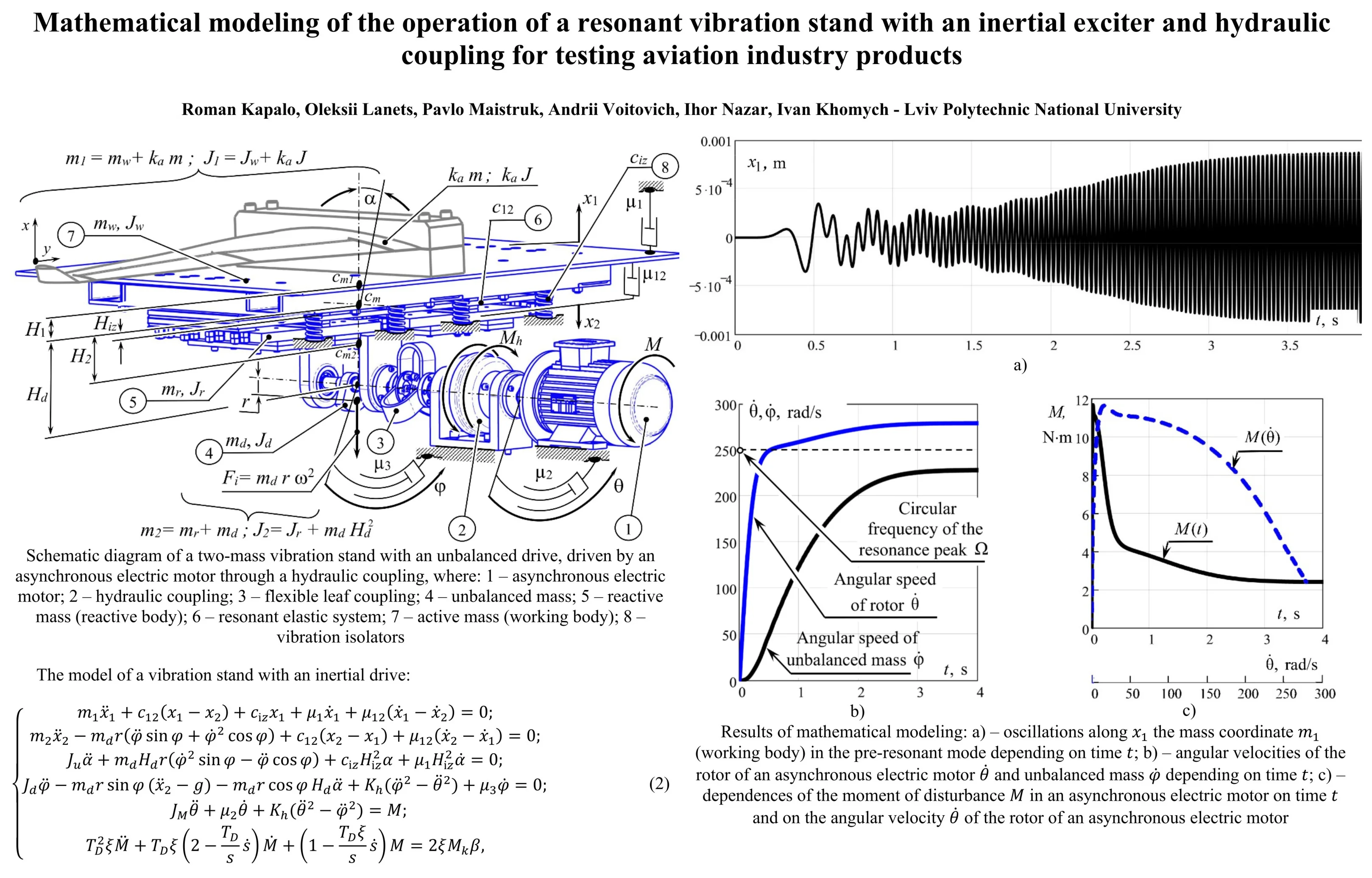
Fig. 1Schematic diagram of a two-mass vibration stand with an unbalanced drive, driven by an asynchronous electric motor through a hydraulic coupling, where: 1 – asynchronous electric motor; 2 – hydraulic coupling; 3 – flexible leaf coupling; 4 – unbalanced mass; 5 – reactive mass (reactive body); 6 – resonant elastic system; 7 – active mass (working body); 8 – vibration isolators
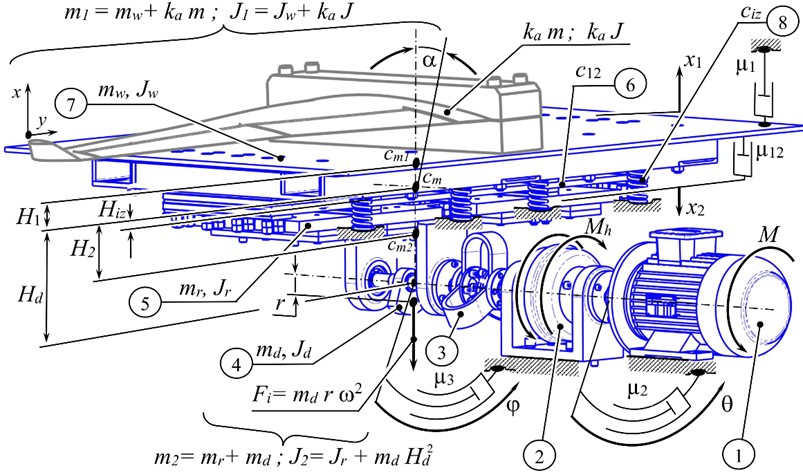
The two-mass vibration stand contains a reactive body 5 (oscillating mass with a total moment of inertia ). An unbalanced mass 4 is attached to the reactive body from below. Taking into account the inertia of the unbalanced mass, the reactive body 5 will have a mass and a moment of inertia . The working body 7 is connected to the reactive body 5 through flat resonant springs 6, the stiffness coefficient of which is . The structure is mounted on a fixed base through vibration isolators 8, the stiffness coefficient of which is . The vibration isolators are attached to the mass .
Forced vibration disturbance in the system occurs due to forced rotation with a circular frequency of unbalance by the mass , the center of mass of which is located with eccentricity relative to the axis of rotation of the shaft. The centrifugal force that arises is the cause of a sign-changing force disturbance of the oscillating mass along the axis . The oscillatory motion from the mass through flat resonant springs 6 is transmitted to the oscillating mass . It is assumed that the oscillations of the masses along the axis will be small, and therefore these movements are neglected.
Due to the fact that the shaft of the unbalanced mass is located at a distance from the center of mass of the system, a moment of disturbance arises that rotates the oscillating system in the plane along the independent coordinate . This movement is attributed to parasitic oscillation. The total moment of inertia of the vibration stand relative to the axis passing through the center of mass of the system along the normal to the plane : , where , are the distances by which the centers of mass of the first and second oscillating masses are separated, respectively, relative to the center of mass of the system. The parameter is the distance at which the vibration isolators are located relative to the center of mass of the vibration stand.
The vibration system of the vibration stand is set in motion as follows. The rotor of the asynchronous electric motor 1 (Fig. 1) begins to rotate after it is turned on. Its motion is described by the moment of disturbance and the angle of rotation . The asynchronous motor drives the drive shaft of the hydraulic coupling 2. The total moment of inertia of the rotor of the asynchronous electric motor and the drive shaft of the hydraulic coupling is denoted by . The revolutions from the driven shaft of the hydraulic coupling, described by the angle of rotation , are transmitted to the unbalance mass 4 through the flexible coupling 3. The total moment of inertia of the driven shaft of the hydraulic coupling and the shaft with the unbalanced mass is denoted by . The torque transmitted by the fluid coupling, is described by the following expression: , where is the coefficient of the hydraulic coupling, which depends on its design parameters and the properties of the fluid filling the coupling.
In the dynamic model in the form of dampers, viscous friction coefficients are introduced, which are proportional to the speed. The coefficient reflects the external viscous resistance to the movement of the mass , caused by the influence of the load mass and the influence of vibration isolators 8. The coefficient describes the dissipation of energy in the resonant elastic system 6; – viscous friction during rotation along the coordinate of the rotor of the electric motor 1 and the driving shaft of the hydraulic coupling 2; – viscous friction during rotation of the driven shaft of the hydraulic coupling and the unbalanced mass 4 along the coordinate , and .
3. Setting key inertial, stiffness and force parameters of a vibration stand
The derivation of analytical dependencies for the formation of system parameters is presented in [3]. Having developed a spatial model of the vibration stand using the SolidWorks software, it was established that the inertial values of the vibration stand: kg; kg. Total stiffness of vibration isolators 1⋅105 N/m. We assume that the nominal rotational speed of the asynchronous motor 298.5 rad/s (2850 rpm). We assume that the resonant circular frequency of the natural oscillations of the two-mass vibration stand 250 rad/s. The required stiffness coefficient of the resonant elastic system in this case is 3⋅106 N/m.
We assume that the amplitude of oscillations of the working body mm is equivalent 5 to the overload, since in this case the overload is 0.0008⋅2502 / 9.81 = 5 (here – the acceleration of gravity). This parameter is sufficient in practice to ensure effective vibrational compaction of the medium. Assume that the value of the eccentricity of the imbalance (the displacement of the center of mass of the imbalance relative to the axis of rotation) is m. In this case, the inertial value of the unbalanced mass of the imbalance is:
During the calculations, the required drive power was also calculated, which is kW. An asynchronous motor of the 4A80A2Y3 model with a power of 1.5 kW was selected as the drive. The viscosity coefficient was calculated from the condition that the coefficient of internal frequency-independent friction is 0.03 m3s, and therefore 500 N·s/m. The remaining viscous resistance coefficients were calculated with the following parameters: N·s/m; 4⋅10-3 N·s·m/rad. The remaining system parameters: m; m – the combined distance at which the vibration isolators are located relative to the center of mass of the vibration stand; ; = 0.00168 kg·m2; kg·m2.
4. Mathematical model of a vibration stand
Before writing the differential equations of motion of the vibration stand, it is necessary to clearly establish the generalized coordinates that will determine the number of equations. So, the two oscillating masses of the vibration stand 7 and 5 (Fig. 1) perform rectilinear oscillations along the vertical axis in independent coordinates and . The oscillating system of the vibration stand rotates by an angle around its own center of mass . The imbalance 4 and the driven shaft of the hydraulic coupling 2 rotate by an angle . The rotor of the electric motor 1 and the driving shaft of the hydraulic coupling 2 rotate by an angle . There are already five generalized coordinates: , , , , . The sixth generalized coordinate is introduced to describe the electric motor. For this purpose, the well-known model of an asynchronous motor [10] was used (in our case, the model will describe the 4A80A2Y3 motor with a power 1.5 kW).
Taking into account materials [6]-[10], the system of differential equations describing the motion of a mechanical oscillatory system, reproducing the model of a vibration stand with an inertial drive, has the form:
where – the torque of an asynchronous electric motor, which in the system of differential equations is an independent coordinate; – critical (maximum torque); ; – relative slip; 314 rad/s – synchronous angular speed of rotation of the rotor of the electric motor; – angular speed of rotation of the rotor of the electric motor; – current slip; – electromagnetic time constant; 314 rad/s – circular frequency of the voltage in the power supply network; – critical slip; 0.05 – nominal slip; rad/s – nominal circular speed of rotation of the rotor of the electric motor; ; ; ; , – respectively, nominal and starting torques in the electric motor. Note that time does not enter explicitly into the system of differential Eq. (2).
5. Results of mathematical modeling of a vibration stand
To solve the system of differential Eq. (2) numerically, it is presented in normal form with respect to second-order derivatives in generalized coordinates , , , , and . Using the parameters given above, system of differential Eq. (2) is solved in the Matcad 13 software using the Runge-Kutta method (Fig. 2).
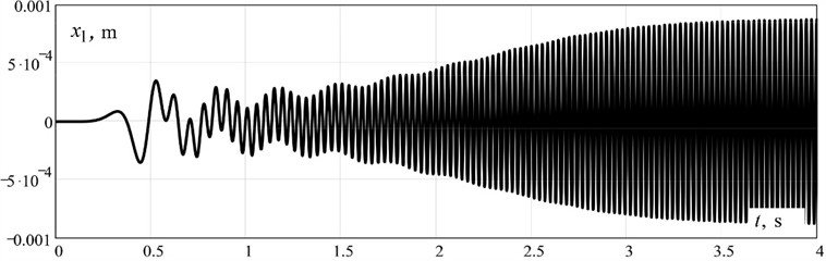
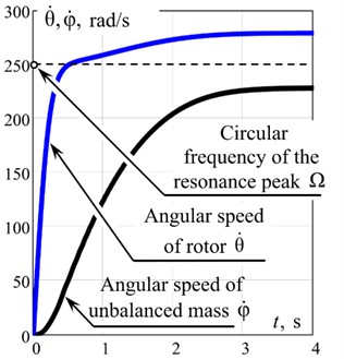
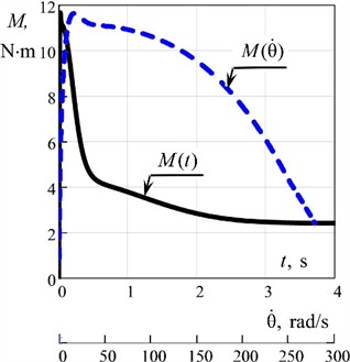
Fig. 2Results of mathematical modeling: a) – oscillations along x1 the mass coordinate m1 (working body) in the pre-resonant mode depending on time t; b) – angular velocities of the rotor of an asynchronous electric motor θ˙ and unbalanced mass φ˙ depending on time t; c) – dependences of the moment of disturbance M in an asynchronous electric motor on time t and on the angular velocity θ˙ of the rotor of an asynchronous electric motor
a)
b)
c)
The time dependences of the movement of the oscillating masses in the first second after starting the vibration stand indicate that the established values of the amplitude of oscillations of the working body (mass ) mm. The rotor speed of the electric motor reaches the expected nominal mode in the vicinity of 298.5 rad/s. The unbalanced mass speed “hangs” in the vicinity of the resonant circular frequency 250 rad/s due to the use of the hydraulic coupling. The vibration stand operates in a stable pre-resonant mode of the system's relative natural peak. The results of the numerical analysis are in good agreement with the planned ones.
6. Conclusions
The article confirms that, provided that the oscillation system is driven by asynchronous electric motors through hydraulic couplings, it is possible to ensure stable operation of vibration technological equipment in a near-resonant operating mode.
The mathematical model reproduced the effect of “hanging” (Sommerfeld effect) of unbalanced mass rotations in the vicinity of the system’s natural oscillation frequency. Thus, the possibility of creating energy-saving designs implemented using resonant operating modes was confirmed using the example of a two-mass vibration stand with an inertial drive.
References
-
M. Böswald and Y. Govers, “Taxi vibration testing – an alternative method to ground vibration testing of large aircraft,” in International Conference on Noise and Vibration Engineering, pp. 2413–2426, 2008.
-
A. Olejnik, S. Kachel, R. Rogólski, and M. Szcześniak, “Technology of ground vibration testing and its application in light aircraft prototyping,” in MATEC Web of Conferences, Vol. 304, p. 01005, Dec. 2019, https://doi.org/10.1051/matecconf/201930401005
-
O. Lanets, Fundamentals of Analysis and Design of Vibratory Machines. (in Ukrainian), Lviv, Ukraine: Lviv Polytechnic Publishing House, 2018.
-
Z. V. Despotovic, A. M. Pavlovic, and D. Ivanic, “Exciting force frequency control of unbalanced vibratory actuators,” in 20th International Symposium on Power Electronics (Ee), pp. 1–6, Oct. 2019, https://doi.org/10.1109/pee.2019.8923574
-
V. Gursky, I. Kuzio, P. Krot, and R. Zimroz, “Energy-saving inertial drive for dual-frequency excitation of vibrating machines,” Energies, Vol. 14, No. 1, p. 71, Dec. 2020, https://doi.org/10.3390/en14010071
-
V. Gursky, P. Krot, V. Korendiy, and R. Zimroz, “Dynamic analysis of an enhanced multi-frequency inertial exciter for industrial vibrating machines,” Machines, Vol. 10, No. 2, p. 130, Feb. 2022, https://doi.org/10.3390/machines10020130
-
O. Lanets, Y. Shpak, V. Lozynsky, and P. Leonovych, “Implementation of the Sommerfeld effect in a vibrating platform with an inertial drive,” (in Ukrainian), Industrial Process Automation in Engineering and Instrumentation, Vol. 47, pp. 12–28, 2013.
-
P. Maistruk, O. Lanets, V. Maistruk, and I. Derevenko, “Establishment of the natural frequency of oscillations of the two-dimensional continuous member of the vibrating table,” Journal of Theoretical and Applied Mechanics, Vol. 52, No. 3, pp. 199–214, Aug. 2022, https://doi.org/10.55787/jtams.22.52.3.199
-
P. Maistruk, O. Lanets, and V. Maistruk, “Determining the influence of continuous section shape and dimensions on stresses over a wide range of vibration frequency,” Ukrainian Journal of Mechanical Engineering and Materials Science, Vol. 10, No. 4, pp. 54–69, Jan. 2024, https://doi.org/10.23939/ujmems2024.04.054
-
W. Wenske, “On the derivation of the dynamic characteristic of the asynchronous motor with regard to the calculation of vibration phenomena in propulsion systems,” (in German), Scientific Journal of the O. Guericke University of Technology, Vol. 14, No. 5/6, pp. 517–523, 1970.
About this article

The authors have not disclosed any funding.
The datasets generated during and/or analyzed during the current study are available from the corresponding author on reasonable request.
