Abstract
The article presents a methodology for modernizing a two-mass resonant electromagnetic vibration stand for testing parts of the aviation industry for vibration resistance. The main goal of the modernization is to provide a significantly lower disturbance force from electromagnetic vibration exciters to set the working body in motion. For this purpose, by introducing a third oscillating mass into the two-mass mechanical system, the interresonant mode of operation of the vibration stand is ensured. Analytical dependencies are presented that reveal the methodology for calculating inertial and stiffness parameters that ensure the transformation of a two-mass resonant vibration system into a three-mass interresonant vibration system. A specific example demonstrates the implementation of the proposed approach in the modernization of the design. The amplitude-frequency characteristics of the basic two-mass resonant and modernized three-mass interresonant vibration systems are constructed. It has been confirmed that to ensure the specified amplitude of oscillations of the working body in the modernized design, 4 times less disturbing force from electromagnetic vibration exciters (400 N) is required.
Highlights
- The article presents an approach to the modernization of a two-mass resonant electromagnetic vibration stand for testing parts.
- By introducing a third oscillating mass into the mechanical system, the interresonant mode of operation of the vibration stand was implemented.
- For a more complete analysis of the energy consumption of the modernized designs, it is necessary to compile their full dynamic models and conduct appropriate experimental studies.
1. Introduction
In practice, there is often a need to modernize existing equipment by increasing its operating efficiency. These issues are also acute when designing vibration stands for testing parts of the aviation industry [1]-[3]. In this article, modernization is understood as reducing the specific costs of drive power for driving a mechanical vibration system, provided that the necessary technological indicators are provided. Reducing drive power indirectly comes down to comparing the disturbance force, which directly affects the power consumed. It is extremely cost-effective not to spend money on introducing new equipment into production, but to modernize basic designs, converting them into highly efficient (energy-saving) equipment. Similar problems are covered in the works [4]-[6].
Scientific works [7]-[10] represent developments of three-mass interresonant oscillatory systems, which are much more energy-efficient compared to classical two-mass designs. Their peculiarity is that the oscillation perturbation in such systems occurs between two resonant peaks. The summation of two resonant peaks allows for the accumulation of a high dynamic potential of the oscillatory system in a relatively narrow frequency range. Due to this, such oscillatory systems can have significantly higher mass dynamic coefficients compared to classical two-mass resonant systems. With the same values of perturbing forces, it is possible to realize significantly higher amplitudes of mass oscillations. Therefore, interresonant oscillatory systems are called highly efficient. Based on the materials [11], the authors of the article propose an approach that provides the transformation of the classical two-mass resonant vibration system of a vibration stand into a three-mass interresonant vibration system.
2. Description of the basic two-mass and upgraded three-mass vibration stands
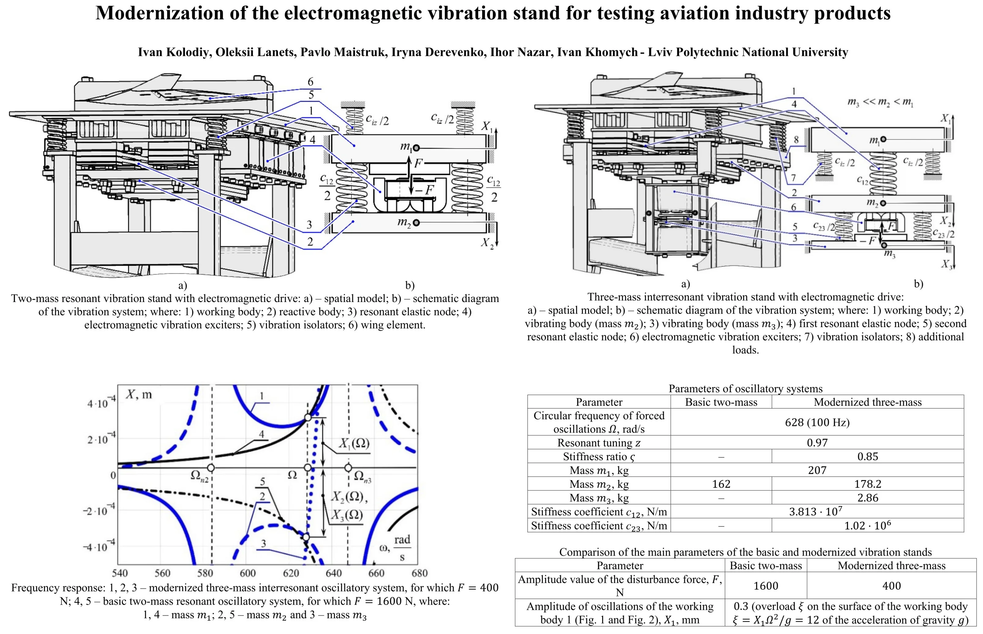
The basic two-mass resonant vibration stand with an electromagnetic drive is shown in Fig. 1. The stand contains a working body 1 (oscillating mass ). A wing element 6, which requires testing for vibration resistance, is installed on the working body. The mass of the wing element is taken into account in the inertial characteristic of the working body. The dynamic influence of the wing element during the synthesis of parameters is neglected. The working body 1 is connected through a resonant elastic node 3 to a reactive body 2 with a mass . The stiffness coefficient of the resonant elastic node 3 is . The structure is mounted on a fixed base through vibration isolators 5, the stiffness coefficient of which is . The vibration isolators are attached to the working body 1 with a mass . The force perturbation of oscillations at the circular frequency of forced oscillations occurs due to electromagnetic vibration exciters 4, the anchors of which are fixed to the working body 1, and the core with coils to the reactive body 2. The working and reactive bodies oscillate in steady-state modes according to the amplitudes of oscillations , .
To ensure the resonant mode of operation in a two-mass oscillatory system, the stiffness coefficient of the resonant elastic unit is set according to the dependence [11]:
where 0.94,…, 0.98 is the resonant tuning of the oscillatory system.
Fig. 1Two-mass resonant vibration stand with electromagnetic drive: spatial model and schematic diagram of the vibration system; where: 1) working body; 2) reactive body; 3) resonant elastic node; 4) electromagnetic vibration exciters; 5) vibration isolators; 6) wing element
As can be seen from Fig. 1, eight electromagnetic vibration exciters 4 are used to drive the vibration system. The efficiency of this design fully corresponds to classical two-mass vibration systems operating in pre-resonant operating modes.
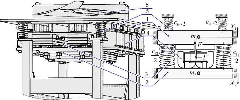
The modernization of the vibration stand in Fig. 1 is as follows. A third vibrating body 3 with a mass (Fig. 2) is introduced into the system, which is connected to the vibrating body 2 with a mass through the second resonant elastic node 5, the stiffness coefficient of which is . The vibrating body 3 in this design is reactive, and the vibrating body 2 is intermediate. As in the basic vibration stand, the working body 1 is connected to the intermediate body 2 with a mass through the first resonant elastic node 4, the stiffness coefficient of which is . The structure is mounted on a fixed base through vibration isolators 7, the stiffness coefficient of which is . The vibration isolators are attached to the working body 1 with a mass . The force perturbation of oscillations at the frequency of forced oscillations occurs due to electromagnetic vibration exciters 6, the anchors of which are fixed to the reactive mass 3, and the core with coils to the intermediate mass 2. As can be seen from Fig. 2, two electromagnetic vibration exciters are used to drive the modernized vibration system. The working, intermediate, and reactive masses oscillate in steady-state modes with the oscillation amplitudes , and .
Fig. 2Three-mass interresonant vibration stand with electromagnetic drive: spatial model and schematic diagram of the vibration system; where: 1) working body; 2) vibrating body (mass m2); 3) vibrating body (mass m3); 4) first resonant elastic node; 5) second resonant elastic node; 6) electromagnetic vibration exciters; 7) vibration isolators; 8) additional loads
3. Analytical dependencies for setting the parameters of a three-mass interresonant oscillatory system
The vibration stand (Fig. 2) is made with an interresonant mode of operation. In this case, the stiffness coefficient of the elastic unit 5 is set according to the dependence [11]:
where – dimensionless coefficient (stiffness fraction ). The parameter is set constructively within , and resonant tuning is always assumed . Recommended values 0.7…0.9; 0.94…0.98 (a more justified choice of parameters is given in [11]). Resonant tuning positions the oscillatory system in the pre-resonant mode relative to the third natural circular frequency and in the post-resonant mode relative to the second natural circular frequency . The first natural circular frequency of the system , caused by vibration isolators, is not taken into account, because vibration isolators are neglected when calculating the parameters.
From Eq. (3), the stiffness coefficient of the elastic node 4 is determined:
Analytical dependencies (2) and (4) are connected through the parameter and fix the third natural circular frequency of the system with the value , and the second natural circular frequency is set depending on the choice of the parameter value . The parameter redistributes the inertial-stiffness parameters in the oscillatory system so that the perturbation of the system at the circular frequency of forced oscillations occurs in the interresonant zone, and . The inertial value of the reactive mass in interresonant oscillatory systems is set according to the dependence [11]:
4. Methodology for upgrading a two-mass vibration test bench
The approach to the modernization of a two-mass resonant vibration stand with an electromagnetic drive (Fig. 1) is as follows. It is assumed that the basic two-mass oscillatory system is structurally included in the three-mass oscillatory system (Fig. 2), and the elastic node 4 with stiffness and the working body 1 with mass remain unchanged. There is a correction of the inertial value of the intermediate body 2 with mass , to which the reactive body 3 with mass is attached.
Following the above-mentioned features of structural modernization, substituting Eq. (5) into Eq. (3), the inertial value of the mass is determined:
Eq. (6) is used to correct the mass two-mass structure (Fig. 1). The correction involves a slight increase in mass. After that, the mass (Eq. (5)) and the stiffness coefficient are given constructively by the parameter 0.6…0.9, which is thoroughly substantiated in [11], and determined (Eq. (2)). The formed reactive body and elastic unit are additionally introduced into a two-mass structure (Fig. 1). Thus, a three-mass interresonant oscillatory system is formed (Fig. 2).
5. An example of transforming a two-mass resonant vibration stand into a three-mass interresonant system
Table 1 shows the parameters of the basic resonant two-mass and three-mass interresonant oscillation systems of vibration stands. The parameters of the two-mass oscillation system to be modernized are known. Parameters such as and are included in the three-mass oscillatory system without changes. The remaining parameters are adjusted or calculated for the given , .
Table 1Parameters of oscillatory systems
Parameter | Basic two-mass | Modernized three-mass |
Circular frequency of forced oscillations , rad/s | 628 (100 Hz) | |
Resonant tuning | 0.97 | |
Stiffness ratio | – | 0.85 |
Mass , kg | 207 | |
Mass , kg | 162 | 178.2 (calculated according to Eq. (6)) |
Mass , kg | – | 2.86 (calculated according to Eq. (5)) |
Stiffness coefficient , N/m | 3.813×10⁷ (calculated according to expression (1). The same result is given by Eq. (4)) | |
Stiffness coefficient , N/m | – | 1.02×10⁶ (calculated according to Eq. (2)) |
As can be seen from Table 1, the inertial value of the intermediate body 2 (mass ) (Fig. 2) must be increased by 16.2 kg. For this purpose, additional loads 8 were introduced. The reactive mass 3 and the elastic unit 5 were structurally designed to provide the parameters given in Table 1.
To ensure better efficiency of the modernized vibration stand, it is necessary to construct the frequency response of the oscillatory systems. For a two-mass oscillatory system, this characteristic is established according to the dependencies [11]:
where ; – variable circular frequency of forced oscillations, rad/s; – amplitude value of the disturbance force of electromagnetic vibration exciters. For a three-mass oscillatory system, the frequency response is established according to the dependencies:
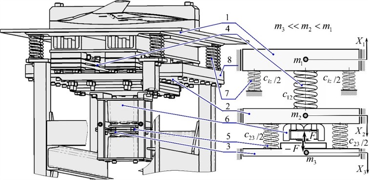
According to the frequency response (Fig. 3), to ensure the given amplitude of oscillations of the working body, the modernized stand consumes 4 times less disturbance force compared to the base model.
Fig. 3Frequency response: 1, 2, 3 – modernized three-mass interresonant oscillatory system, for which F= 400 N; 4, 5 – basic two-mass resonant oscillatory system, for which F= 1600 N, where: 1, 4 – mass m1; 2, 5 – mass m2 and 3 – mass m3
The frequency response is constructed without taking into account the viscous resistance coefficients in oscillatory systems. The main results of the modernization are shown in Table 2.
Table 2Comparison of the main parameters of the basic and modernized vibration stands
Parameter | Basic two-mass | Modernized three-mass |
Amplitude value of the disturbance force, , N | 1600 | 400 |
Amplitude of oscillations of the working body 1 (Fig. 1 and Fig. 2), , mm | 0.3 (overload on the surface of the working body of the acceleration of gravity ) | |
However, it is necessary to note the following. The 4-fold reduction in the disturbance force was obtained theoretically, and, in practice, this result will be adjusted. This is due to the fact that the proposed approach increases the efficiency of the functioning of only the oscillatory system, and the power spent on performing work on the loading medium remains the same. In addition, due to the presence of dissipation in the system, it will not be possible to ensure ideal in-phase motion of masses and subjected to force perturbation. A relatively ultra-light mass kg may have unstable oscillations, since its frequency response in the vicinity of the forced oscillation frequency has a steep characteristic and is sensitive to changes in parameters.
6. Conclusions
The article presents an approach to the modernization of a two-mass resonant electromagnetic vibration stand for testing parts. By introducing a third oscillating mass into the mechanical system, the interresonant mode of operation of the vibration stand was implemented. Due to this, to set the working body in motion, it is necessary to spend much less disturbance force from electromagnetic vibration exciters compared to the base model. Thus, to ensure the amplitude of oscillations of the working body 0.3 mm at the frequency of forced oscillations 628 rad/s (100 Hz), the modernized design requires an amplitude value of the disturbance force 400 N, and the base design 1600 N. For a more complete analysis of the energy consumption of the modernized designs, it is necessary to compile their full dynamic models and conduct appropriate experimental studies. These works will be carried out in further studies. The proposed modernization methodology can be used for vibration equipment in various industries.
References
-
M. Arena et al., “Vibration response analysis of a main landing gear system for high in-flight dynamic loadings,” Journal of Physics: Conference Series, Vol. 2716, No. 1, p. 012025, Mar. 2024, https://doi.org/10.1088/1742-6596/2716/1/012025
-
A. Olejnik, S. Kachel, R. Rogólski, and M. Szcześniak, “Technology of ground vibration testing and its application in light aircraft prototyping,” in 9th EASN International Conference on Innovation in Aviation and Space, Vol. 304, p. 01005, Dec. 2019, https://doi.org/10.1051/matecconf/201930401005
-
M. Böswald and Y. Govers, “taxi vibration testing – an alternative method to ground vibration testing of large aircraft,” in International Conference on Noise and Vibration Engineering, pp. 2413–2426, 2008.
-
V. Gursky, “Implementation of dual-frequency resonant vibratory machines with pulsed electromagnetic drive,” Przegląd Elektrotechniczny, Vol. 1, No. 4, pp. 43–48, Apr. 2019, https://doi.org/10.15199/48.2019.04.08
-
V. Korendiy et al., “Kinematic and dynamic analysis of three-mass oscillatory system of vibro-impact plate compactor with crank excitation mechanism,” Vibroengineering Procedia, Vol. 40, pp. 14–19, Feb. 2022, https://doi.org/10.21595/vp.2022.22393
-
O. O. Cherno and A. Y. Kozlov, “Modeling of a controlled electromagnetic vibration drive with a variable resonant frequency,” Tekhnichna Elektrodynamika, Vol. 2023, No. 4, pp. 62–71, Jun. 2023, https://doi.org/10.15407/techned2023.04.062
-
P. Maistruk, O. Lanets, V. Maistruk, and I. Derevenko, “Establishment of the natural frequency of oscillations of the two-dimensional continuous member of the vibrating table,” Journal of Theoretical and Applied Mechanics, Vol. 52, No. 3, pp. 199–214, Aug. 2022, https://doi.org/10.55787/jtams.22.52.3.199
-
M. Pavlo, L. Oleksii, and S. Vadym, “Approximate calculation of the natural oscillation frequency of the vibrating table in inter-resonance operation mode,” Strojnícky časopis – Journal of Mechanical Engineering, Vol. 71, No. 2, pp. 151–166, Nov. 2021, https://doi.org/10.2478/scjme-2021-0026
-
P. Maistruk, “Optimization of the shape and dimensions of the continuous section of the discrete-continuous inter-resonance vibrating table,” Ukrainian Journal of Mechanical Engineering and Materials Science, Vol. 9, No. 3, pp. 10–20, Jan. 2023, https://doi.org/10.23939/ujmems2023.03.010
-
V. Gursky and O. Lanets, “Modernization of high frequency vibratory table with an electromagnetic drive: theoretical principle and modeling,” Mathematical Models in Engineering, Vol. 1, No. 2, pp. 34–42, 2015.
-
O. Lanets, Fundamentals of Analysis and Design of Vibratory Machines. (in Ukrainian), Lviv, Ukraine: Lviv Polytechnic Publishing House, 2018.
About this article

The authors have not disclosed any funding.
The datasets generated during and/or analyzed during the current study are available from the corresponding author on reasonable request.
