Abstract
The mathematical model of the movement of an arbitrary point of the container of a vibrating separator with a pneumatic suspension is built in the article. For modeling, a vibrating separator with two independently driven unbalances and a pneumatic suspension was chosen, which has a number of advantages over other separators, is characterized by simplicity of construction and maintenance, and low sensitivity to the properties of the medium being separated. The developed unified parameterized model of a vibrating separator can be used by changing its parameters or zeroing them for a wide range of designs of vibrating separators. The use of data from ready-made unified mathematical models allows you to reduce the duration of research and design of vibrating separators, and reduce material costs in general.
Highlights
- The mathematical model of the movement of an arbitrary point of the container of a vibrating separator with a pneumatic suspension is built.
- Based on the constructed mathematical model, the influence of the pneumatic cushion on the amplitude of vertical vibrations of the vibrating separator was investigated.
- During the calculations the oscillating mass is considered constant and is taken to be 150 kg. The imbalances rotate in different directions and their revolutions are equal to 750 rpm. The torque is 44.78 Nm. The eccentricity of the unbalance is 35.997 mm.
1. Introduction
The conditions of a modern market economy require high productivity and efficiency of production, as well as minimizing energy and material consumption, taking into account the negative impact on the environment. The equipment used in industrial production must be reliable, compact, energy-efficient, and easily adaptable for different types of products. The development of optimal designs and operating modes for equipment at the design stage is crucial to meeting these requirements. In general, modern separation technologies play an important role in production, enabling manufacturers to achieve greater productivity and market stability while maintaining high standards of quality and environmental safety. There is a wide variety of separator designs, so considerable attention is paid to studying their operating principles, increasing productivity, and developing new prototypes. In modern conditions, the processes of separating various mixtures of substances are actively studied, and new designs of separators are developed, which are distinguished by high efficiency and universal application. The development of modern separators and the determination of optimal operating modes are key tasks for ensuring high efficiency and quality of separation processes. Therefore, based on the developed model of a vibrating separator with pneumatic suspension [1], a study was conducted to investigate the influence of its amplitude-frequency characteristics on the efficiency of the separation process.
2. Referencing
Modern research pay considerable attention to the modeling and optimization of vibrating separator designs due to their widespread use in various industries. They show that an adequate model of the separator dynamics (taking into account the geometry of the sieves, excitation modes and interaction with the material) allows predicting performance and minimizing problems such as clogging and uneven distribution on the web [1-3]. Changing the trajectory of the sieve movement (for example, from linear to elliptical) affects the intensity of sieving and reduces clogging, which is confirmed by both numerical experiments and full-scale tests [4].
DEM modeling has become a standard tool for studying the microdynamics of particles on the sieve surface [5]. The works reproduce contact interactions, agglomeration, the formation of stagnation zones and the influence of regime parameters on throughput. The combination of DEM with optimization methods allows finding the best design parameters without expensive experiments [6].
Multiphase modeling, in particular the DEM-CFD coupling, allows for the simultaneous description of the behavior of solid particles and the influence of the environment, especially in the case of wet processes or in the presence of gas flows [7, 8]. Such models take into account the effects of film formation and hydrodynamic damping, which is important for processes with pneumatic or hydraulic support.
Engineering developments include the use of multi-frequency excitation systems [6], topological optimization of load-bearing elements to reduce weight and increase rigidity [9], as well as the use of energy-efficient solutions in drives [10]. Work also focuses on reducing noise and vibration in industrial screens [11], and reliability analysis allows for the identification of vulnerable nodes and an increase in equipment resource [12, 13].
The maintenance problem is solved through the use of machine learning and artificial intelligence algorithms [14] that predict the state of nodes and automatically adjust operating modes in response to changes in material properties or operating conditions.
A separate area of research is devoted to the physical mechanisms of vibrational segregation of granulate and the formation of structures in thin layers of material [15, 16], which creates a basis for a deeper understanding of processes in real industrial conditions.
Thus, the analysis of recent publications shows that the processes of vibrational separation are described by different approaches, which make it possible to consider vibrational separators of individual models. Therefore, it is proposed to build a mathematical model of a vibrational separator, which could describe dynamic processes in separators of different types and areas of application.
3. Main material
The presence of a pneumatic suspension allows for a smooth and simple change in its stiffness [1], which, in turn, makes it possible to adjust the amplitude of the separator's oscillations. Such a change is achieved by adjusting the air pressure in the pneumatic suspension cylinders. In particular, when turning on and off the drive motors, the stiffness of the suspension should be reduced as much as possible so that the separator passes through the resonance zone, where vibrating machines of this type operate at a minimum frequency. This reduces the operational load on the moving parts and components of the separator, which is the greatest during resonance. This also allows for normal operating conditions with lower power of the drive motors. The latter reduces energy consumption for the operation of the separator and reduces the requirements for the strength and material consumption of the separator supports.
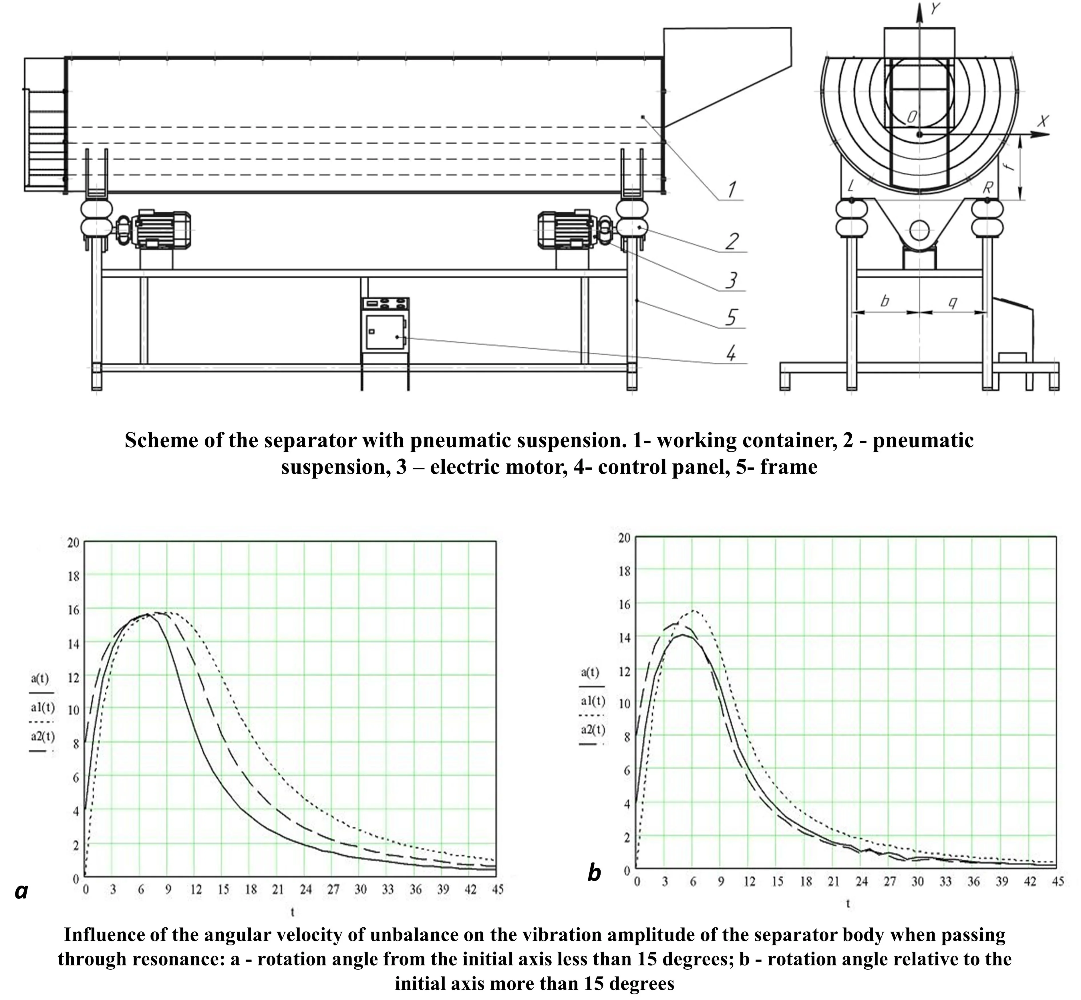
To build a mathematical model of the motion of a vibration separator, it is necessary to focus on a certain class of separators that are used in industry and have positive differences compared to other types of separators. For this purpose, the work selected and studied a model of the motion of a vibration separator with two independently driven unbalanced vibration exciters and a pneumatic suspension (see Fig. 1). Such separators have a number of advantages, which include the implementation of vibrations of various shapes, simplicity of design, versatility for modeling, the possibility of using software for them based on the developed mathematical models and conducted research.
To study the motion of a vibration separator, it is necessary to build a system of analytical expressions that will take into account all the parameters of the installation. It will be based on differential equations that describe the motion of a vibration separator. When substituting the necessary parameters of the separator into them, we will obtain equations for determining the amplitude and frequency of oscillation of a selected point of the separator body. That is, the basis of the mathematical model of the motion of the working container of the vibrating separator will be the law of motion of the base point (center of mass of the separator). Therefore, the equations of the center of mass will be determined:
where and – coordinates of the center of mass of the separator container, and – coordinates of the centers of mass of the first and second imbalances, respectively.
Fig. 1Scheme of the separator with pneumatic suspension: 1 – working container, 2 – pneumatic suspension, 3 – electric motor, 4 – control panel, 5 – frame
From Eq. (1) it is clear that the coordinates of the center of mass of the mechanical system are complex functions of the geometric and kinematic parameters of the working container and the drive. Therefore, the geometric center of the container of the vibration separator should be chosen as the base point. Accordingly, the changes in the vertical and horizontal coordinates of the unbalances and the center of mass of the separator container in time consist of the geometric parameters of the system and the coordinates of the center of the container. That is, they are functions of the latter. Therefore, the generalized coordinates of the system will be taken as linear movements of the geometric center of the container , , and also the angle of rotation of the moving coordinate system (the separator's working container) relative to the stationary one (the angle of rotation of the container around its own center of mass).
The center of mass of the unbalances and the container relative to the YOX coordinate system will have the following coordinates:
– for the container:
– for the 1st imbalance:
To determine the deformation of the air suspension, we write down the coordinates of the points of attachment of the springs to the body through generalized coordinates:
where – points of attachment of the air suspension to the separator body. – distances from the suspension supports to the fixed coordinate system of the separator ( and , respectively)
The Lagrangian of this mechanical system, taking into account Eq. (2-5), will take the form:
where are the masses of the container, unbalances and suspension, respectively. Differentiating the expressions and substituting the obtained derivatives for each generalized coordinate into the Lagrange equation of the second kind, we reduce them to the following form:
Taking into account the relationship between the coordinates of the container points relative to two reference systems – stationary and moving (relationship with the geometric center of the vibrating separator container), it is possible to determine the horizontal and vertical components of the amplitude of oscillations of an arbitrary point of the vibrating separator container in the plane of its movement – in the plane of oscillations of imbalances at any moment of time or during the period of operation of the vibrating separator during the separation of loose materials, and to construct the trajectory of the movement of this point during the studied time interval of processing, to find the influence of all kinematic and geometric parameters of the vibrating separator (embedded in the model in symbolic form) on the amplitude of oscillations of any point of the working container, to investigate their significance in terms of influence on the magnitude of the amplitude and nature of oscillations of the vibrating separator container, as well as with their arbitrary variation among themselves, over the entire interval of possible changes in these parameters.
When building a mathematical model of a vibrating separator, the dimensions of the installation were selected based on the averaged indicators of their productivity. The length of the drum in this version is 2500 mm, the inner diameter of the drum is 800 mm, the thickness of the drum wall is 3 mm. Specific separation conditions are taken into account by introducing a number of coefficients that depend on the characteristics of the amount of the source material, separation efficiency, grain shape, separation method, etc.
Based on the constructed mathematical model, the influence of the pneumatic cushion on the amplitude of vertical vibrations of the vibrating separator was investigated. This will allow adjusting the efficiency of the separation process, because the intensity of the interaction of the mixture with the sieves is determined mainly by the magnitude of vertical vibrations. The oscillating mass is considered constant and is taken to be 150 kg. The imbalances rotate in different directions and their revolutions are equal to 750 rpm. The torque is 44.78 Nm. The eccentricity of the unbalance is 35.997 mm, and the mass of each unbalance is taken equal to 1.244 kg.
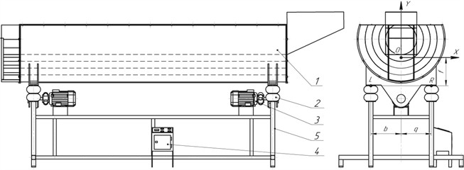
Below, Fig. 2 and Fig. 3 show the dependence of the amplitude (mm) of vibrations of the vibrating separator housing on the angular speed of rotation of the unbalance.
Fig. 2Influence of the angular velocity of unbalance on the vibration amplitude of the separator body when passing through resonance: at-ω= 110 rad/sec, a1t-ω= 150 rad/sec, a2t-ω= 130 rad/sec), rotation angle from the initial axis less than 15 degrees
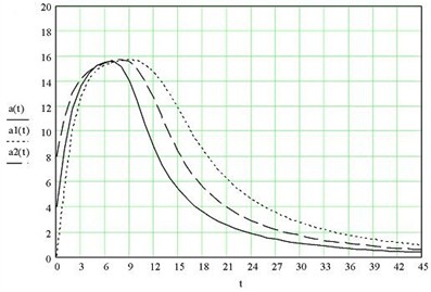
Fig. 3Influence of the angular velocity of unbalance on the vibration amplitude of the separator body when passing through resonance: at-ω= 150 rad/sec, a1t-ω= 130 rad/sec, a2t-ω= 110 rad/sec), rotation angle relative to the initial axis more than 15 degrees
4. Conclusions
The constructed mathematical model of the vibration separator covers all the dynamic phenomena occurring in it. It allows to study the influence of its basic parameters (parameters that can be changed during the operation of the separator) on the amplitude of oscillations of the vibration separator container, to obtain graphical dependences of the amplitude of oscillations of the separator container on its parameters and the trajectory of movement of arbitrary points of the container in the plane of its oscillations. These dependences can be used to select the necessary operating modes of the separator. Verification of the results of studies of the dynamics of the separator using modeling in Mathcad showed sufficient consistency. Accordingly, the study of the dynamics of vibration separation systems for their design and optimization of operation using applied systems is quite accurate. The resulting model can be used to compare dynamic processes in the developed experimental prototypes.
References
-
D. Rebot, V. Topilnytskyy, I. Svidrak, R. Stotsko, and A. Shevchuk, “Constructing the schematic and mathematical model of the dynamics of a vibratory drum separator,” Vibroengineering Procedia, Vol. 55, pp. 33–39, Sep. 2024, https://doi.org/10.21595/vp.2024.24434
-
O. Kachur, V. Korendiy, O. Lanets, R. Kachmar, I. Nazar, and V. Heletiy, “Dynamics of a vibratory screening conveyor equipped with a controllable centrifugal exciter,” Vibroengineering Procedia, Vol. 48, pp. 8–14, Feb. 2023, https://doi.org/10.21595/vp.2023.23175
-
V. B. Lalwani, J. V. Desai, and D. H. Pandya, “Dynamic motion analysis of reciprocating vibro-separator,” in Lecture Notes in Mechanical Engineering, Singapore: Springer Singapore, 2020, pp. 195–205, https://doi.org/10.1007/978-981-15-3746-2_18
-
V. Korendiy, O. Kachur, R. Predko, O. Kotsiumbas, R. Stotsko, and M. Ostashuk, “Generating rectilinear, elliptical, and circular oscillations of a single-mass vibratory system equipped with an enhanced twin crank-type exciter,” Vibroengineering Procedia, Vol. 51, pp. 8–14, Oct. 2023, https://doi.org/10.21595/vp.2023.23657
-
H. Chowdhury, Z. Xie, and Y. Shen, “Superquadric DEM study of the particle separation process in a multi-deck banana vibrating screen,” Advanced Powder Technology, Vol. 36, No. 9, p. 105003, Sep. 2025, https://doi.org/10.1016/j.apt.2025.105003
-
P. Arunyanart and S. Sudsawat, “DEM simulation for the predicted model of total rice seeds mass in a vibratory conveyor,” International Journal of Engineering and Technology, Vol. 15, No. 4, pp. 161–165, Nov. 2023, https://doi.org/10.7763/ijet.2023.v15.1240
-
R. K. Soni, S. Jaiswal, S. Dash, and C. Eswaraiah, “CFD and DEM numerical modelling of industrial vibrating desliming screen for performance optimization and minimal misplacement,” Powder Technology, Vol. 426, p. 118630, Aug. 2023, https://doi.org/10.1016/j.powtec.2023.118630
-
R. Guizani, H. Mhiri, and P. Bournot, “Numerical investigation of the vortex breaker for a dynamic separator using computational fluid dynamics,” Journal of Applied Fluid Mechanics, Vol. 16, No. 6, 2023.
-
A. Patel and S. Bhattacharya, “Multi-frequency vibration screens: modeling and application,” International Journal of Mineral Processing, Vol. 174, pp. 12–20, 2018, https://doi.org/10.1016/j.minpro.2017.12.003
-
L. Chen and W. Yang, “Structural optimization of vibrating screens using topology methods,” Structural and Multidisciplinary Optimization, Vol. 66, pp. 143–157, 2022, https://doi.org/10.1007/s00158-022-03118-0
-
Y. Li et al., “Numerical study on the screening performance of a cylindrical vibrating screen with coupled rotation and vibration,” International Journal of Mechanical and Electrical Engineering, Vol. 6, No. 1, pp. 49–63, May 2025, https://doi.org/10.62051/ijmee.v6n1.07
-
X. Sun, Y. Sui, Y. Zheng, L. Wang, and H. Zhu, “Finite element analysis and optimization design of large vibrating screen based on equivalent static load method,” Engineering Research Express, Vol. 6, No. 1, p. 015528, Mar. 2024, https://doi.org/10.1088/2631-8695/ad3520
-
T. M. Lenkovskiy et al., “An effective crack tip region finite element sub-model for fracture mechanics analysis,” Archives of Materials Science and Engineering, Vol. 2, No. 87, pp. 56–65, Oct. 2017, https://doi.org/10.5604/01.3001.0010.7446
-
T. Wu, S. Gong, G. Zhao, N. Xu, B. Liu, and F. Zhang, “Separation mechanism and kinematic characteristics of particles on screen panel with different vibration modes,” Physicochemical Problems of Mineral Processing, Vol. 61, No. 4, p. 20544, May 2025, https://doi.org/10.37190/ppmp/205443
-
D. Rebot, V. Topilnytskyy, T. Stefanovych, and S. Shcherbovskykh, “Vibration oscillations modeling for printed boards of machine control units during their operation,” in 2023 17th International Conference on the Experience of Designing and Application of CAD Systems (CADSM), pp. 1–4, Feb. 2023, https://doi.org/10.1109/cadsm58174.2023.10076529
-
S. Ahmed and R. Khan, “Reliability analysis of vibratory separators in continuous operation,” Proceedings of the Institution of Mechanical Engineers, Part C: Journal of Mechanical Engineering Science, Vol. 233, No. 16, pp. 5572–5585, 2019, https://doi.org/10.1177/0954406219846456
About this article

The authors have not disclosed any funding.
The datasets generated during and/or analyzed during the current study are available from the corresponding author on reasonable request.
The authors declare that they have no conflict of interest.
