Abstract
The article presents a developed 3D model of a vibration separator with an unbalanced drive and pneumatic suspension. The created model is parametric, allowing for modifications to the design of the vibration separator based on the area of application. The welded separator housing was selected as the main assembly unit of the model. Using Autodesk Inventor Professional, a strength analysis of the vibration separator was carried out to confirm its operational reliability. The study evaluated whether the designed structure can withstand the applied operational loads, and parametric optimization was performed to reduce the mass of the vibrating part of the separator while maintaining its structural strength. This approach enables engineers to tailor the separator design to various industrial applications and optimize material utilization without compromising durability.
Highlights
- Using Autodesk Inventor Professional, a strength analysis of the vibration separator was carried out to confirm its operational reliability.
- The performed strength calculation and modal analysis showed that the maximum stress of 34.9 MPa and the corresponding minimum safety factor of 5.93 are observed in the welded areas of the frame elements under the drive.
- The frequency of the vibrating mass — that is, the frequency of the dynamic force applied to the frame — is 24 Hz, given a drive motor angular velocity of 151 rad/sec. Eight natural frequencies of the frame were determined automatically.
1. Introduction
The use of vibration separators in industry requires both the optimization of existing models and the development of new ones to improve performance and efficiency. Based on the developed utility model [1], a 3D model of a vibration separator with pneumatic suspension was created, and its structural strength was analyzed. This allows for parametric optimization of the separator and the selection of design parameters for its components depending on changes in the main assembly. In the calculations, the welded housing of the vibration separator is considered the primary component. Additionally, Autodesk Inventor Professional enables the automated generation of a complete set of technical documentation for prototype manufacturing. Preliminary modeling, strength analysis, and operational verification of the separator help prevent future failures or breakdowns due to overloads or improperly configured modes, while also optimizing the separation process to achieve maximum possible productivity.
2. Referencing
The conducted literature review has shown that, to date, vibration separators have not been sufficiently studied. Most publications focus on individual models or specific use cases. For example, in [2], a disc-type vibration separator is investigated, analyzing separation efficiency depending on changes in vibration as the bowl load increases. In [3], experimental research was carried out to optimize the parameters of a pneumatic-impulse vibration separator. The study identified optimal oscillation frequencies of the separating surface and the best pulsation frequencies of the airflow. In [4], a study on the effect of bulk material moisture, sieve inclination angle, and vibration frequency on the separation efficiency of a vibrating separator is presented. References [5,6] explore the potential to improve the efficiency of vibrational pneumatic separators based on newly developed models, taking into account the effects of vibration frequency, air velocity, and moisture content of the feed layer. In [7], a computational model of a vibration separator with additional elastic elements between the housing and the drive's bearing units is proposed. Based on the mathematical model, the operation of the separator’s drive and its influence on separation performance were analyzed, leading to optimization of structural elements, particularly the working surface. In [8], a comparison between theoretical modeling and experimental research was made for a vibration separator used with composite materials, considering the effects of material feed speed and the vibration frequency of the separator’s housing. The minimal error between results allows for further expansion of such studies to other industrial separator models. In [9, 10], mathematical modeling was used to examine how changes in amplitude and frequency of the container's oscillation in a vibrating screen affect productivity and optimal operational modes.
The overall review demonstrates that there are relatively few modern publications dedicated to the study of various vibration separator models, and newly developed designs still require in-depth analysis. Given the lack of similar studies in current literature, this work presents a strength analysis of a patented model [1].
3. Main material
To create a parametric model of a separator with an unbalanced drive and pneumatic suspension, it is necessary to select a main part or assembly, the modification of which would lead to changes in the entire structure [11]. In this case, the welded drum housing has been chosen as the primary component. The input variables for the drum were defined as: drum length, inner drum diameter, and wall thickness – three independent parameters. The first two determine the internal volume of the drum, which is directly related to the separator’s capacity and overall machine dimensions, while the third affects the structural strength of the drum, which functions as the vibrating working element of the machine.
Other drum parameters were derived as mathematical dependencies based on these input variables. In this context, mathematical modeling of vibrational processes can be effectively applied [12]. When defining the geometries of other separator components, the drum parameters were linked using external references. Additionally, ribs, planes, and surfaces of the drum were connected through associative relationships and projected geometry – capabilities that are well-implemented in the Autodesk Inventor Professional CAD system. The developed 3D model of the vibration separator is shown in Figs. 1 and 2.
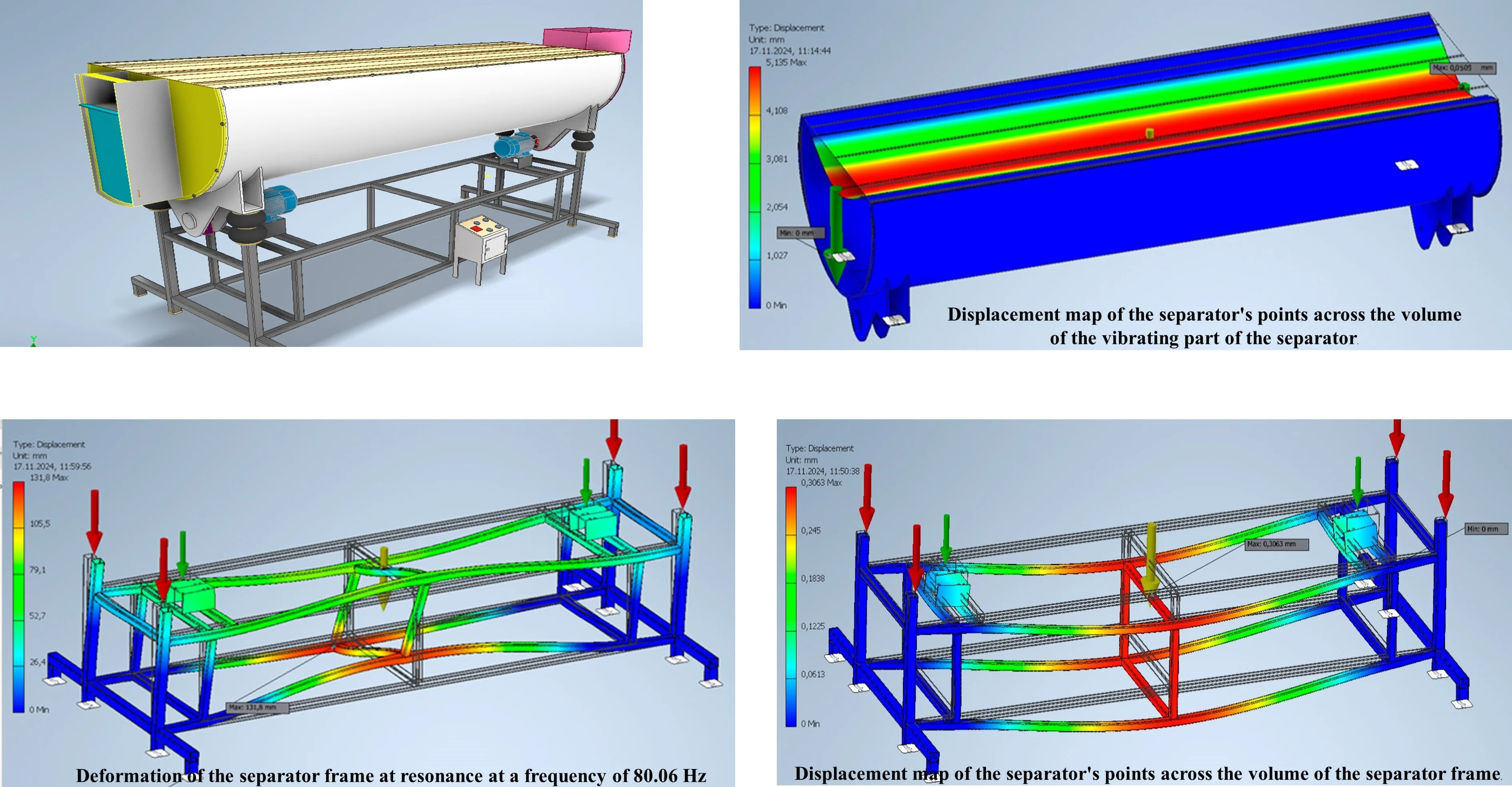
Fig. 1Three-dimensional computer model of a vibration separator with an unbalanced drive and pneumatic suspension
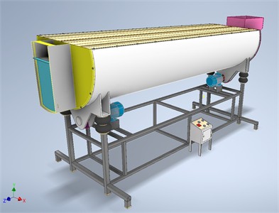
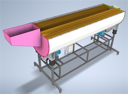
Fig. 2Model of the vibration separator with an unbalanced drive and pneumatic suspension without the top cover
The strength analysis of the separator enables the evaluation of whether the developed structure can withstand the operational loads applied to it. Also allows conducting parametric optimization aimed at reducing the mass of the vibrating part while maintaining its structural integrity. In this study, the vibration separator was divided into two main parts. The first is the movable vibrating part, which includes the drum, covers, sieves, unbalanced masses, and partially the couplings. The second part is the frame of the separator, which remains static during operation. The interaction between these two parts was substituted by appropriate active and reactive forces. Some forces, such as air resistance or temperature effects, were neglected due to their negligible impact within the scope of this analysis. They will be added in future studies, provided that the vibrating separator is located outside the premises.
The maximum load mass for the analysis was set at 400 kg. The mass of the four sieves, assuming a thickness of 2 mm, was estimated at 160 kg. During the study, the drum wall thickness varied from 1 mm to 3 mm with a step of 0.25 mm, resulting in nine test iterations. The optimization criteria were defined as follows:
a) The minimum required safety factor of the structure is 2.
b) The maximum acceptable mass of the drum is 120 kg.
c) The maximum displacement of any point on the structure under load must not exceed 0.06 mm.
In the initial design (Figs. 1-2), the drum wall thickness was 3 mm, resulting in a drum mass of 132.371 kg (automatically calculated using Autodesk Inventor).
At research step I (wall thickness = 1 mm): Criterion a: 1.61 – not satisfied; Criterion b: 87.266 kg – satisfied; Criterion c: 0.168 mm – not satisfied; Conclusion: A 1 mm wall thickness is unsuitable, as none of the three criteria are fully met. Similar results were observed for steps II through IV, where one or more criteria were not met. At step V (wall thickness = 2 mm): Criterion a: 2.91 – satisfied; Criterion b: 117.352 kg – satisfied; Criterion c: 0.0509 mm – satisfied; Conclusion: A wall thickness of 2 mm meets all optimization criteria and is therefore considered optimal. At step VI, although criteria a and c were satisfied, criterion b was not, as the drum mass exceeded 120 kg (124.863 kg). Thus, the optimal drum wall thickness for this separator is 2 mm, ensuring structural strength and meeting all performance requirements.
As a result of these automated parametric analyses, the vibrating mass of the separator was reduced by 15.019 kg (from 132.371 kg to 117.352 kg). The displacement map across the volume of the vibrating part of the separator is shown in Figs. 3 and 4.
Fig. 3Displacement map of the separator’s points across the volume of the vibrating part of the separator
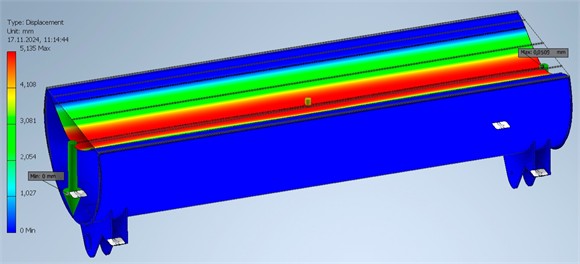
As evident from the above research results, the maximum stress and, consequently, the minimum safety factor is observed at the drum ends and at the welded joints connecting the drum to the mounting elements of the pneumatic suspension (Fig. 3, Fig. 4). The maximum displacement of the points of the vibrating part of the separator occurs along the central section of the horizontal (top) drum cover.
The second stage involves the strength analysis of the separator frame. It must be sufficiently rigid to withstand the oscillating vibrating mass of the drum, covers, sieves, load, and drive. The active forces acting on the frame include: the gravitational force of the frame itself (automatically applied to its center of mass by the system), and the dynamic force from the vibrating mass of the separator. This latter force is calculated as the vibrating mass of the separator increased by 25 %, accounting for the fact that this mass is in motion. When the direction of motion changes, the inertial forces cause the vibrating mass to momentarily increase, exerting additional pressure on the supports. This dynamic force is evenly distributed among the four mounting points where the pneumatic suspension cylinders are attached to the frame. Based on the calculations presented above, the force acting on each frame support equals 2000 N. The reactive force applied to the frame corresponds to the reaction forces from the workshop floor acting upward along the frame legs [13].
The results of the frame strength analysis are shown in Fig. 5.
Fig. 4Displacement map of the separator’s points across the volume of the vibrating part of the separator
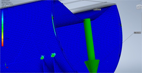
Fig. 5Displacement map of the separator’s points across the volume of the separator frame
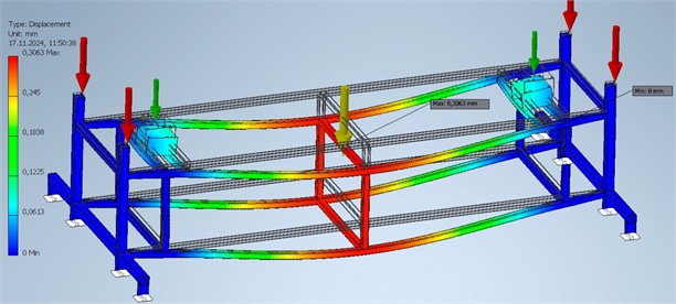
As evident from the research results presented above, the maximum stress of 34.9 MPa and the corresponding minimum safety factor of 5.93 are observed at the welded joints of the frame elements beneath the drive (Fig. 5). The maximum displacement of 0.3 mm in the points of the vibrating part of the separator occurs in the central area of the frame, vertically downward. The calculated strength parameters indicate that the frame can withstand the applied operational loads. Therefore, the frame has been properly designed, and the selected profiles are appropriate. The minimum safety factor is not excessively high, meaning the frame is not overly material-intensive.
Additionally, a modal analysis was performed on the frame to determine its natural vibration frequencies. The vibration frequency of the vibrating mass, i.e. the frequency of the dynamic force acting on the frame is 24 Hz, based on a drive motor angular velocity of 151 rad/sec. Autodesk Inventor Professional automatically identified 8 (user-defined number) natural frequencies of the frame (Figs. 6-7).
If the natural frequency of the frame coincides with the frequency of the applied external force, resonance vibrations may occur in the frame, potentially leading to structural damage. The conducted analysis showed that the minimum natural frequency of the frame is 40.27 Hz, which significantly exceeds the frequency of the external excitation force. Therefore, the structural integrity of the frame is ensured in this aspect as well.
Fig. 6Deformation of the separator frame at resonance at a frequency of 80.06 Hz
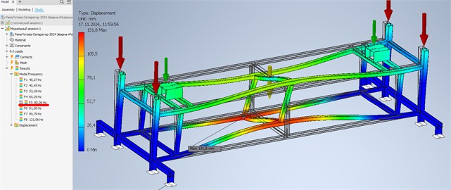
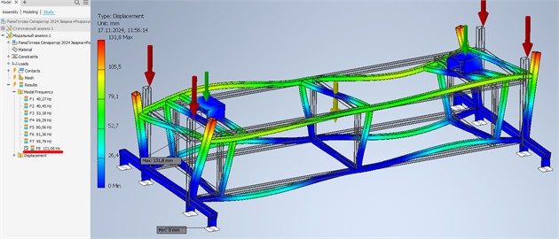
Fig. 7Deformation of the separator frame at resonance at a frequency of 121.06 Hz
4. Conclusions
The performed strength calculation and modal analysis showed that the maximum stress of 34.9 MPa and the corresponding minimum safety factor of 5.93 are observed in the welded areas of the frame elements under the drive. The maximum displacement of 0.3 mm in the vibrating part of the separator occurs in the central part of the frame in the vertical downward direction. The calculated values of strength parameters indicate that the frame can withstand the applied operational loads. Therefore, the frame is properly designed, and the selected profiles are appropriate. Since the minimum safety factor is not excessively high, the frame is not overly material-intensive.
The frequency of the vibrating mass – that is, the frequency of the dynamic force applied to the frame – is 24 Hz, given a drive motor angular velocity of 151 rad/sec. Eight natural frequencies of the frame were determined automatically. The analysis showed that the minimum natural frequency of the frame is 40.27 Hz, which significantly exceeds the frequency of the external force. Thus, the structural integrity of the frame is ensured in this aspect as well.
The obtained results may further be considered when comparing theoretical and experimental data and can be used in the design and optimization of vibrating separator structures.
References
-
D. Rebot and V. Topilnytskyy, “Drum vibrating separator,” Utility model patent No. 153808, 2024.
-
N. Janssen et al., “The impact of particle deposition on the vibration of a disk stack separator – development of a soft-sensor for determining the separation efficiency,” Separation Science and Technology, Vol. 60, No. 6, pp. 749–760, Apr. 2025, https://doi.org/10.1080/01496395.2025.2453888
-
S. P. Stepanenko and D. A. Volyk, “Results of experimental researches of the vibro-pneumopulse separator for separating seeds by density,” Mechanics and Automatics of Agroindustrial Production, pp. 61–75, Jan. 2024, https://doi.org/10.37204/2786-7765-2024-2-7
-
B. K. Shanmugam, H. Vardhan, M. Govinda Raj, M. Kaza, R. Sah, and H. Hanumanthappa, “Evaluation of the parametric effects of separation of coal in vibration separator using Plackett-Burman design of experiments,” Transactions of the Indian Institute of Metals, Vol. 76, No. 5, pp. 1243–1252, Dec. 2022, https://doi.org/10.1007/s12666-022-02842-9
-
M. Hajad, R. H. Amrullah, and M. Dzulkifli, “Design and multi-objective optimization of vibro-pneumatic separator for paddy pre-cleaning using RSM,” in IOP Conference Series: Earth and Environmental Science, Vol. 1287, No. 1, p. 012030, Dec. 2023, https://doi.org/10.1088/1755-1315/1287/1/012030
-
V. Bredykhin, A. Bogomolov, L. Kis-Korkishchenko, A. Pak, and A. Pak, “Proving the possibility to rationalize the process of seed materials separation with a vibro-pneumatic centrifugal separator using a theoretical model,” Eastern-European Journal of Enterprise Technologies, Vol. 6, No. 1 (126), pp. 13–21, Dec. 2023, https://doi.org/10.15587/1729-4061.2023.291114
-
O. Omelyanov and O. Tokarchuk, “Substantiation of amplitude-frequency characteristics and design parameters of the separator with a vibration drive,” Vibrations in engineering and technology, Vol. 1(104), pp. 30–37, Apr. 2022, https://doi.org/10.37128/2306-8744-2022-1-4
-
H. Li, E. Zhou, L. Shen, Z. Yin, and Z. Bo, “Dynamical characteristics and vibration behavior of the novel composite dry separator,” Vibroengineering Procedia, Vol. 40, pp. 1–6, Feb. 2022, https://doi.org/10.21595/vp.2022.22350
-
D. Popolov, S. Shved, H. Zaitsev, S. Henkulenko, and O. Shumylo, “Laboratory studies on the effect of vibro-impact action of the screening surface on the main technological indicators of metallurgical raw material screening,” Economics and technical engineering, Vol. 3, No. 1, pp. 95–105, Jul. 2025, https://doi.org/10.62911/ete.2025.03.01.09
-
L. Q. Meng and Z. W. Wang, “Multi-Objective Optimization Design of Vibration Screener Support Spring Parameters with Vibration Mechanics,” Applied Mechanics and Materials, Vol. 252, pp. 144–148, Dec. 2012, https://doi.org/10.4028/www.scientific.net/amm.252.144
-
D. Rebot, V. Topilnytskyy, S. Shcherbovskykh, and T. Stefanovych, “Study of the efficiency of using ateb-functions in modeling oscillatory processes for networks,” in 2023 IEEE 18th International Conference on Computer Science and Information Technologies (CSIT), pp. 1–4, Oct. 2023, https://doi.org/10.1109/csit61576.2023.10324209
-
O. Arkhipov, O. Bondarenko, and Y. Koretskyi, “Creating a parametric model of an automotive assembly in the Autodesk Inventor software,” Modern problems of modeling, Vol. 26, No. 26, pp. 3–13, Jun. 2024, https://doi.org/10.33842/2313125x-2024-26-3-13
-
S. Arya, M. O. ’Neill, and G. Pincus, Design of Structures – Foundations for Vibrating Machines. Huston, USA: Gulf Publishing Company, Book Division, 1984.
About this article

The authors have not disclosed any funding.
The datasets generated during and/or analyzed during the current study are available from the corresponding author on reasonable request.
The authors declare that they have no conflict of interest.
