Abstract
For battery transport containers, model processing, seismic and road vibration response analyses were conducted. Modal analysis was carried out to obtain the 1st to 10th order natural frequencies (7.38-105.10 Hz) and combined with the design response spectrum to calculate the total response. The boundary conditions were fixed anchor bolts, with 350 kg point masses added to the supports to simulate battery packs, and the damping coefficient was 2 %. According to the IEEE693 standard, seismic waves were input, and the analysis showed that the maximum stresses of the battery pack bracket and the container body were 158 MPa and 241.8 MPa respectively, both lower than the allowable seismic strength, which could provide a basis for seismic design. For road vibration response, random vibration analysis based on the power spectral density theory was used, with an appropriate frequency range selected and data input with reference to the GB4857.23 standard. The simulation showed that the maximum stresses of the battery pack bracket and the container body were 100 MPa and 106 MPa respectively, both lower than the allowable transportation vibration strength of 118 MPa, which could provide references for structural optimization and improve transportation safety and economy.
Highlights
- Modal analysis was carried out to obtain the 1st to 10th order natural frequencies (7.38-105.10Hz) and combined with the design response spectrum to calculate the total response.
- For road vibration response, random vibration analysis based on the power spectral density theory was used, with an appropriate frequency range selected and data input with reference to the GB4857.23 standard.
- Through the establishment of a refined finite element model for battery transport containers, a systematic investigation has been conducted on their dynamic behaviors under seismic excitation and road unevenness conditions.
1. Introduction
Containers are confronted with severe vibration challenges in complex transportation environments, and this issue directly restricts the improvement of transportation quality [1-3]. The diversity and complexity of vibration excitation sources are its prominent features. In highway trunk transportation, the impact between high-speed vehicles and uneven road surfaces, the periodic vibration of engines, and the transient load generated by transmission gear shifting will form wide-frequency vibrations ranging from 1 to 50 Hz. In railway transportation, the periodic impact from wheel-rail contact, the step effect of track joints, and the centrifugal force when trains pass through curves will trigger vibration responses in the range of 2 to 100 Hz. Marine transportation is more complex. The pitching, rolling and heaving motions of ships in waves, combined with the mechanical vibrations of the main engine and propeller, will lead to the coupling effect of low - frequency swaying (0.1-20 Hz) and high-frequency vibrations.
Representative studies on the seismic performance of containers include: Bac [4] conducted dynamic characteristic analysis on the container by using three different types of seismic waves and obtained the load responses under various working conditions. Lima [5] adopted the finite element method to conduct modal simulation on the key components of the container, obtaining the vibration modes and natural frequencies, which provided a basis for structural optimization. Ye [6] proposed a modal analysis method that can obtain the dynamic response of large containers under complex working conditions. The maturity of computer-aided finite element simulation technology provides a revolutionary solution to break through the bottleneck of vibration analysis [7]. By discretizing the container into thousands of finite element units and combining material constitutive relations and boundary conditions, this technology can accurately simulate the stress distribution, displacement response and modal characteristics of the box body under multi-directional vibration loads. However, in current major research, the combination of modal characteristics derived from finite element analysis and dynamic load response characteristics is often overlooked. This is not conducive to the safety verification of key components of containers under different excitation conditions during long-term transportation. For this reason, based on modal analysis, this paper predicts the seismic and road responses of containers respectively to ensure that they meet the operational requirements.
The innovative aspects of this paper lie in leveraging advanced computer simulation techniques, encompassing finite element analysis, response spectrum analysis, and random vibration analysis, to delve into the vibration response characteristics of containers within complex environments. Through the establishment of a refined finite element model for battery transport containers, a systematic investigation has been conducted on their dynamic behaviors under seismic excitation and road unevenness conditions. The structural safety has been validated via stress analysis, and the key factors influencing the vibration response have been determined.
2. Simulation and analysis of vibration characteristics
2.1. Model processing
The characteristics of the container finite element model are reflected in several aspects. It can accurately simulate the mechanical behavior of containers under different working conditions, including stress distribution and deformation when bearing loads, providing a reliable basis for structural design and strength analysis. The model usually includes relatively complex geometric features, involving various parts of the box such as side plates, top plates, bottom plates, end walls, corner pieces, etc., as shown in Fig. 1(a). The connection relationships between various parts also need to be reflected in detail to reflect the force transmission of the overall structure. At the same time, the model needs to consider multiple load conditions, such as static stacking loads, dynamic impact loads during transportation, and temperature loads in different environments, to comprehensively evaluate the structural performance of the container.
Fig. 1Model simplification
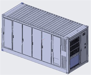
a) The overall structure
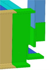
b) Simplification of parts

c) Simplification of assembly
In terms of simplification methods, first, the geometric model can be simplified by ignoring some detailed features that have little impact on the overall structural performance, such as tiny chamfers, local protrusions or depressions, thereby reducing the number of elements in the model and improving calculation efficiency, as shown in Fig. 1(b). Secondly, for the connections between components, simplified connection methods can be adopted according to the actual situation as shown in Fig. 1(c). The actual welding connections, which are either full penetration welds or fillet welds, are simplified in the finite element model as bonded constraints, eliminating the need to model the weld seam entities. Since the model thickness is uniform, shell element types are preferred, which is beneficial for both the efficiency and accuracy of the finite element analysis.. In addition, in terms of load processing, distributed loads can be appropriately simplified and converted into equivalent concentrated loads, or representative areas can be selected for loading according to the distribution characteristics of the loads to reduce the amount of calculation. At the same time, during mesh division, larger mesh sizes can be used in areas where the structural stress changes gently, while finer meshes are used in key areas with stress concentration, realizing reasonable mesh division and balancing calculation accuracy and efficiency. Since the model thickness is uniform, shell element types are preferred, which is beneficial for both the efficiency and accuracy of the finite element analysis. For the treatment of battery mass, remote mass points are attached to the installation nodes of the battery frame, eliminating the need to construct a battery model.
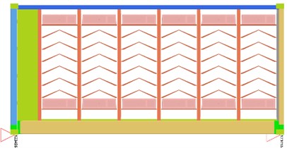
The structure of this container is designed for the transportation of batteries and has multiple layers of battery racks inside. The container has an overall closed rectangular structure, composed of multiple key components. These components are connected by welding and other methods to form a solid integrated structure. Among them, the corner fittings, as important connection nodes, play a key role in the lifting, stacking, and transportation of the container, being able to transmit and bear large loads. The side plates, top plate, and bottom plate usually adopt a corrugated design. This design not only reduces the structural weight but also enhances the rigidity and strength of the plates, and can effectively disperse and resist the pressure caused by external loads. This material properties are shown in Table 1. Both Q345 and Q690 are low-alloy high-strength structural steels, featuring high yield strength and tensile strength, which can meet the strict requirements for structural strength of containers during transportation and stacking. Compared with ordinary carbon steel, under the same stress conditions, using these materials can appropriately reduce the thickness of the plates, thereby reducing the weight of the containers themselves, which is conducive to improving the loading efficiency of transportation tools and reducing fuel consumption. Meanwhile, Q345 and Q690 materials also have good toughness and plasticity, and are less likely to break under impact loads, which can better ensure the safety of goods inside the containers. In addition, these materials have good weldability, facilitating the connection and processing of various components, and are suitable for large-scale industrial production of containers. For the logistics industry, high-strength and lightweight containers improve transportation efficiency, reduce operating costs, and promote the efficient development of global cargo transportation.
Table 1Material properties
Component | Material | Density (kg/m3) | Poisson’s ratio | Elastic modulus (MPa) | Yield strength (MPa) | Seismic failure threshold (MPa) | Transport vibration failure threshold (MPa) |
Battery pack bracket | Q690 | 7850 | 0.29 | 205000 | 690 | 552 | 238 |
Container body | Q345 | 7850 | 0.3 | 210000 | 345 | 275 | 118 |
3. Seismic response analysis
The seismic response of containers requires the use of response spectrum analysis. Therefore, it is necessary to conduct modal analysis in advance to solve the natural frequencies (as shown in Table 2) of the structure, which is the basis of response spectrum analysis. Afterwards, combine the mode shapes of each order of modes with the design response spectrum, calculate the seismic action of each order of modes according to the combination method specified in the code, and combine these actions to obtain the total seismic response of the structure. For the treatment of battery mass, remote mass points are attached to the installation nodes of the battery frame, eliminating the need to construct a battery model. The boundary conditions for the response spectrum analysis are defined as shown in Fig. 2. The anchor bolt positions are set as fixed constraints, and point masses are added to each support to simulate the battery packs, with each mass point weighing 350 kg.
Collate and evaluate the calculation results to determine whether the stress, deformation, etc. of the structure under earthquake action are within the allowable range. The response spectrum analysis plays a significant role. It can efficiently evaluate the dynamic response of containers under earthquake action, avoiding time-consuming time-history analysis, while also well reflecting the impact of seismic loads on the structure. Through this method, the weak parts of the structure under different earthquake intensities can be quickly identified, providing a basis for the seismic design of containers, ensuring that they can maintain the integrity of the structure when an earthquake occurs and protect the safety of the internal goods.
Fig. 2The boundary conditions for the response spectrum analysis
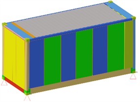
a) The definition of constraint conditions
b) The definition of the point mass unit
Table 2Natural frequencies
Order | 1 | 2 | 3 | 4 | 5 | 6 | 7 | 8 | 9 | 10 |
Natural frequency / Hz | 7.38 | 9.24 | 11.67 | 25.69 | 38.98 | 55.29 | 68.21 | 79.94 | 88.28 | 105.10 |
For response spectrum analysis, the boundary conditions and load handling should conform to the actual working conditions. When simulating additional masses such as battery packs, the position and value of point masses should be set accurately to avoid changes in the dynamic characteristics of the structure due to mass distribution deviations. The selection of damping coefficients should be reasonable, generally determined based on the structure type and relevant specifications. The damping coefficient of the container model is set at 2 %. Both too large or too small values will affect the calculation of response amplitudes.
Fig. 3The spectral curve of seismic waves
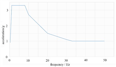
According to the IEEE693 seismic test standard, the seismic wave as shown in Fig. 3 is imported into the load condition. The analysis results are shown in Fig. 4. It can be seen that the maximum stress of the battery pack bracket is 338.44 MPa, which is less than the allowable seismic strength of the material, 552 MPa. The maximum stress of the container body is 241.8 MPa, which is less than the allowable seismic strength of the material, 275 MPa.
Fig. 4Results of seismic response analysis
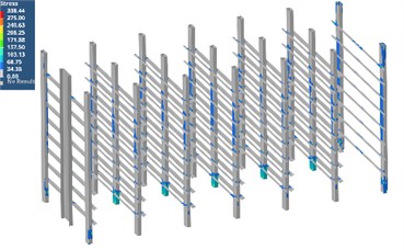
a) The stress response of the battery pack bracket
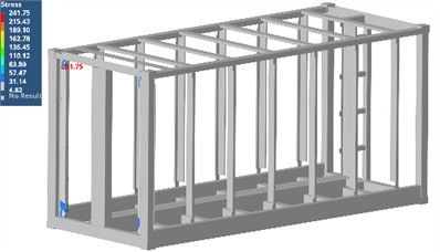
b) The stress response of the container body
4. Analysis of road vibration response
In the analysis of road vibration of containers, random vibration analysis is a commonly used method. Its approach is mainly based on the power spectral density theory. First, the power spectral density function of road surface irregularity is obtained through experiments or theoretical analysis, which can reflect the energy distribution of road surface excitation at different frequencies. Then, this power spectrum is taken as input, combined with the dynamic model of the container, and the response power spectral density of each component of the container is calculated using vibration theory, so as to obtain the statistical characteristics of physical quantities such as vibration displacement, velocity, and acceleration, such as the mean square value. From the perspective of structural safety, through the analysis, the structural reliability of the container in the long-term road transportation vibration environment can be evaluated, and the parts that may be damaged due to vibration fatigue can be found in advance, which provides a basis for structural optimization design and prolongs the service life of the container. In addition, this analysis can also provide references for the design of the suspension system of transport vehicles and the selection of driving routes, which helps to improve the safety and economy of the overall transportation.
The selection of the frequency range should be appropriate. The frequencies covered by the analysis should include the main natural frequencies of the container structure and the main energy distribution range of the road excitation. If the frequency range is too narrow, important vibration components may be missed, affecting the completeness of the results. If it is too wide, it will unnecessarily increase the computational load. Different random vibration analysis methods have their applicable conditions. For example, the modal superposition method is suitable for linear systems. For structures with nonlinear factors, the method should be chosen carefully or appropriate processing should be carried out to avoid errors caused by improper methods. Referring to the standard GB4857.23, the input power spectrum data is as shown in Table 3. Through simulation and calculation, the results of random vibration analysis are presented in Fig. 5. It can be seen that the maximum stress of the battery pack bracket is 156.25 MPa, which is less than the allowable transportation vibration strength of the material, 238 MPa. The maximum stress of the container body is 106.23 MPa, which is also less than the allowable transportation strength of the material, 118 MPa.
Table 3Discrete data of power spectrum
Frequency (Hz) | 1 | 3 | 4 | 8 | 12 | 30 | 40 | 60 |
Power spectral density ((m/s2)2/Hz) | 0.000036 | 0.06 | 0.06 | 0.007 | 0.016 | 0.006 | 0.015 | 0.0014 |
Fig. 5Results of road vibration response
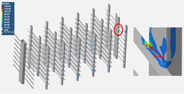
a) The stress response of the battery pack bracket
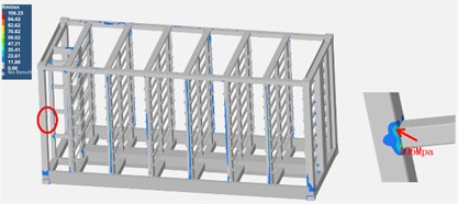
b) The stress response of the container body
5. Conclusions
The container finite element model can accurately simulate mechanical behaviors, including complex components and connections, and needs to consider various loads. Its efficiency is improved through geometric simplification, connection simulation and other methods. Designed for battery transportation, it has a closed rectangular structure and is made of Q345 material, which has the characteristics of high strength and light weight, and is beneficial to the development of logistics. For seismic response analysis, modal analysis is first carried out, and then the total response is obtained by combining with the response spectrum. The boundary conditions include fixed constraints and point masses, etc. The analysis shows that the stress of each component is lower than the allowable value, which can efficiently evaluate the dynamic response and provide a basis for seismic design. Random vibration analysis is used for road vibration response, which is based on the power spectral density theory and requires selecting an appropriate frequency range. After inputting data with reference to standards, the stress of each component meets the standard. This analysis can evaluate the structural reliability, provide references for many aspects, and improve the safety and economy of transportation.
References
-
J.-Y. Wu, Q.-Q. Yu, Q. Peng, and X.-L. Gu, “Seismic responses of liquid storage tanks subjected to vertical excitation of near-fault earthquakes,” Engineering Structures, Vol. 289, p. 116284, Aug. 2023, https://doi.org/10.1016/j.engstruct.2023.116284
-
R. Xue, Z. Ren, T. Fan, and S. Rakheja, “Vertical vibration analysis of a coupled vehicle-container model of a high-speed freight EMU,” Vehicle System Dynamics, Vol. 60, No. 4, pp. 1228–1252, Apr. 2022, https://doi.org/10.1080/00423114.2020.1850810
-
B. K. Meisuh, J. Huh, A. Haldar, and I.-T. Kim, “Comparison of seismic responses of a jumbo-size container crane retrofitted with braces, dampers, and isolation systems,” Ocean Engineering, Vol. 262, No. 15, p. 112222, Oct. 2022, https://doi.org/10.1016/j.oceaneng.2022.112222
-
B. Nguyen, J. Seo, J. Huh, J.-H. Ahn, and A. Haldar, “Seismic response investigation of 1/20 scale container crane through shake table test and finite element analysis,” Ocean Engineering, Vol. 234, No. 1, p. 109266, Aug. 2021, https://doi.org/10.1016/j.oceaneng.2021.109266
-
H. T. Lima, L. E. de M. Alas, M. N. A. Nunes, D. M. de Lima, and I. Da S. Medeiros, “Experimental and numerical modal evaluation of profiled steel decking floor slabs in a container house using MEMS,” Engineering Structures, Vol. 308, p. 117991, Jun. 2024, https://doi.org/10.1016/j.engstruct.2024.117991
-
Y. Lu et al., “Modal investigation on a large-scale containership model for hydroelastic analysis,” Shock and Vibration, Vol. 2022, No. 1, pp. 1–11, Apr. 2022, https://doi.org/10.1155/2022/2539870
-
M. Hamaguchi and T. Yajima, “Vibration control for sloshing in liquid container in cart with active vibration reducer (Transfer on an uneven road),” Mechanical Engineering Journal, Vol. 10, No. 4, pp. 23–136-23-00136, Jan. 2023, https://doi.org/10.1299/mej.23-00136
About this article

The authors have not disclosed any funding.
The datasets generated during and/or analyzed during the current study are available from the corresponding author on reasonable request.
The authors declare that they have no conflict of interest.
