Abstract
This article designs a small-scale farmland rainfall runoff sampler for collecting rainwater during runoff events and performing chemical analysis. The system automatically collects up to 24 samples simultaneously using an STM32 microcontroller as its control unit. The controller adjusts the PWM signal to manage a DC motor's rotation and on/off state, and it accurately positions the sampling bottles via guide slots and position sensors. When the sampling bottle is positioned, the collection end sends a signal to start the peristaltic pump, which delivers water to the receiving end. And The flow rate is measured by a turbine flowmeter equipped with a pulse recorder. After calibration, the error of each 500 ml sample can be controlled within ±2 %, demonstrating relatively high accuracy and making the sampler suitable for actual sampling requirements. Its simple structure also enhances the durability of equipment in complex outdoor environments. Implementing unmanned rainwater collection can save manpower and material costs while avoiding the danger and uncertainty of manual sampling in rainy weather. The cap of the sampling bottle is designed with anti-volatility features to prevent the volatilization of chemicals such as pesticides and fertilizers in the rainwater, which is beneficial for improving the accuracy of soil and water monitoring.
Highlights
- Automatically complete bottle mouth sealing
- Prevent the evaporation of liquid inside the bottle
- Assist the entire bottle in completing the sampling and positioning function
1. Introduction
Although pesticides are effective in controlling pests and diseases, their adverse effects are well known. Excessive application of pesticides not only harms the environment but also causes excessive pesticide residues in crops. Long-term consumption of contaminated crops will poses significant risks to human health [1, 2]. Rainwater flowing through farmland can effectively reflect the application patterns of fertilizers and pesticides. Analysis of rainfall runoff from farmland using rainwater samplers enables monitoring of fertiliser and pesticide application rates, thereby preventing soil contamination caused by excessive use and enhancing the level of ecological environment monitoring in farmland environments [3]. Due to the sporadic nature of rainfall events, manual sampling at experimental sites is highly susceptible to human limitations, resulting in low efficiency and compromised objectivity. With the increasing intelligence of rainfall samplers, traditional manual sampling methods will gradually be superseded due to their low productivity and high labour intensity [4]. Weerasinghe et al. [5] develop an automated rainwater sampling system for real-time acidity monitoring. The system utilizes rainwater samplers to collect water samples for measuring PH and conductivity, while monitoring meteorological parameters such as temperature, humidity, and atmospheric pressure. With high automation and excellent stability, the system provides an efficient solution for remote monitoring applications. Markéta Kaplická et al. [6] employ an automatic samplers to monitor water quality in agricultural runoff, establishing a contaminant concentration-discharge model through correlation analysis, regression analysis, and principal component analysis. Their research successfully quantifies the relationships between farmland pollutant concentrations, precipitation levels, and runoff coefficients. Su et al. [7] design a rainfall runoff sampler enabling timely collection of rainwater with a maximum sampling delay error of 62 seconds and a minimum error of 22 seconds. by the mobile devices, enabling timely collection of rainwater with a maximum sampling delay error of 62 seconds and a minimum error of 22 seconds. However, the rainwater sampling accuracy is not involved. C. Alessia et al. [8] design an automatic precipitation sampler for collecting water-soluble conductive substances deposited in the air in remote environments, but this sampler cannot collect rainwater from surface runoff on farmland. A. Thomas et al. [9] design a rainwater sampler for collecting rainwater to analyze and detecting the concentration of particulate matter in the air. It can collect 24 samples at a time, but the sampler is not highly automated, lacks precise flow control, and is unsuitable for sampling surface runoff from farmland. M. Groning et al. [10] design a rainwater collector that accounts for the evaporation of rainwater. However, it was only suitable for collecting rainwater from the air and is not applicable for collecting surface runoff from farmland. Zhang et al. [11] design a non-electric-powered automatic sampler for urban natural rainfall, resolving the challenge of automatically collecting the initial water samples from natural rainfall and runoff process all day long. It can also record the initial sampling time, though it makes no mention of sampling rainwater in complex environments of remote rural areas. Xu et al. [12] design a drawer-type slope runoff sampler, which can automatically switch between timed sampling and volume-based sampling based on rainfall intensity. This device replaces traditional manual sampling and achieves automated dynamic monitoring of runoff. Zhu et al. [13] develop a mobile phone-controlled water sampler featuring stable communication functionality and excellent sealing properties, capable of fulfilling sampling requirements. However, its automation level remains low, rendering it unsuitable for remote rural areas.
Traditional rainfall-runoff samplers are often hampered by complex mechanical structures, outdated control systems, and inadequate equipment adaptability. To achieve unattended rainwater collection while preventing chemical volatilization, this paper designs a compact agricultural rainfall runoff sampler with automatic sealing functionality for sampling bottles. The sampler has a simple structure, easy operation, and accurate sampling, meeting experimental requirements. The system employs programmable PWM duty cycle control to modulate motor speed, while a position sensor ensures precise sample bottle positioning at 15° increments per sampling cycle. During water extraction by the peristaltic pump, a turbine flow meter counts flow rate in real-time, enabling accurate volume measurement for each sample. The sampler control system measures accurately and has small errors during sampling. Once sampling parameters are configured, personnel can leave the site unattended, enabling autonomous operation in remote or unmanned field locations. This eliminates the safety risks associated with manual sampling during rainy weather conditions. The sampler is ingeniously designed with low cost, and it is easy to commercialize. Its lightweight design facilitates field transportation and the replacement of sampling sites, effectively addressing the current shortage of human resources in remote rural areas. Additionally, the sealing performance of the sampling bottle mouth is excellent, which can effectively prevent the volatilization of chemical substances in rainwater and ensure the long-term sample preservation. The overall design of the system and the anti-volatilization design of the sampling bottles provide valuable reference for field surface water collection, enabling precise analysis of pesticides and fertilizers, and monitoring soil pollution in farmland.
2. Overall design concept
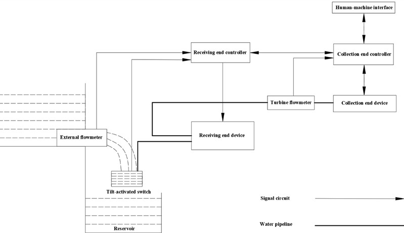
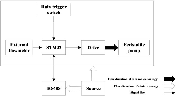
As shown in Fig. 1, the sample is primarily designed with three components: the receiving end, the collection end, and a human-machine interface. The receiving end integrates a pumping device for collecting surface runoff, while the collection end utilizes a filling bottle coupled with a positioning mechanism to ensure orderly loading the collected rainwater into the sample container. The human-machine interface enables both sampling method configuration and real-time sampling status monitoring. The sampler operates in farmland environments with a certain slope, where rainfall runoff converges along the downhill direction into a reservoir serving as the receiving end. When receiving signals from the receiving end, the sampler controls the relay to activate the peristaltic pump, thereby supplying water to the collection end.
Fig. 1The total design of the sampler
3. Structure and working principle
3.1. The collection end structural composition
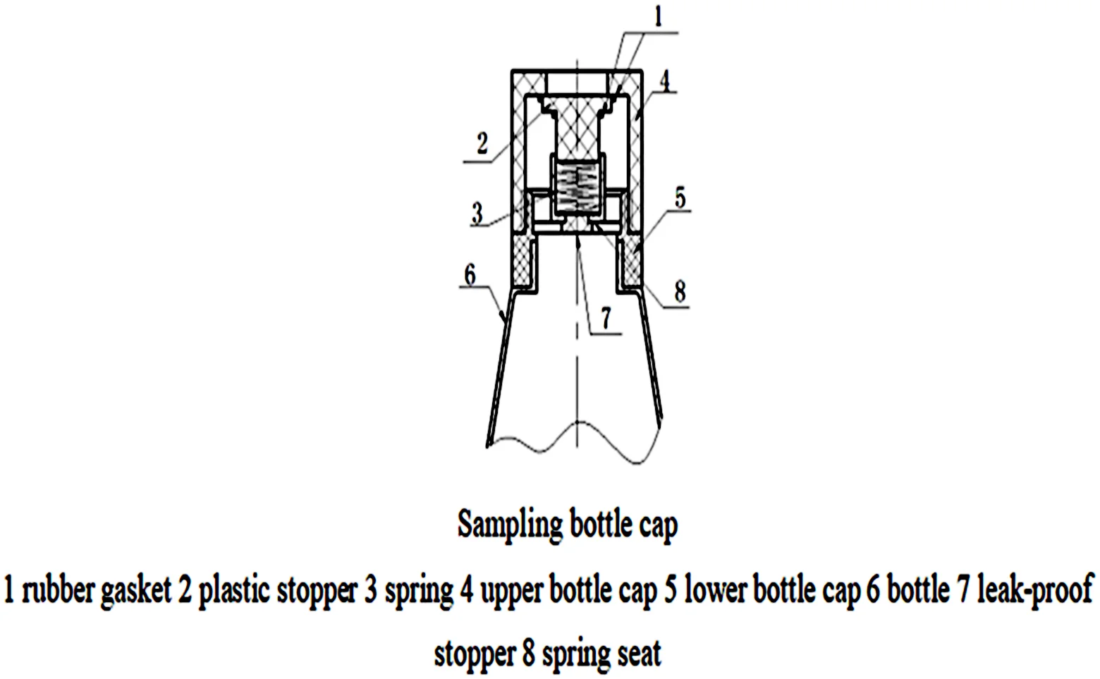
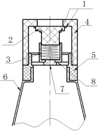
The structure of the collection end device is shown in Fig. 2 and Fig. 3. Fig. 2 is a schematic diagram of the overall structure of the sampler collection end. The collection end is composed of four main parts: a position sensor, guide slot, rotating disc, and DC motor. The DC motor is fixed to its base, while the reducer mounted on the motor shaft is closely assembled with the rotating disc through the flat key. The sampling bottle is replaced by the rotating disc driven by a DC motor. A DC motor typed 24 V with a power of 60 W, torque of 20 N/m, and rated speed of 1800 RPM is used as the power unit at the collection end, and the gear reducer with a reduction ratio of 1:180 is assembled on the motor shaft [14]. The sampling bottle is placed within 24 square holes on the rotating disc. During sampling, the sampling bottle is required to stop at a relatively precise position. Limit switch 9 and capacitive proximity switch 14, as two position sensors, work together to detect and provide real-time feedback on the position of the sampling bottle to ensure accurate positioning for the filling process [15, 16]. Fig. 3 illustrates the schematic diagram of the structure of the bottle filling positioning device. The guide rod is a square rod with internal threads, which is mechanically connected to the motor shaft of the small motor by connecting bolts. The vertical expansion and contraction of the spray nozzle are controlled by the forward and reverse rotation of the small motor. When the small motor rotates forward, the spray nozzle extends downward. When the alignment bolt reaches the position of the proximity switch 16, it indicates that the spray nozzle has entered the mouth of the sampling bottle and meets the requirements of the sampling position. When the sampling is completed, the small motor reverses direction, causing the spray nozzle to retract. The retracted position of the spray nozzle is detected via connection bolt 3 and proximity switch 4. The connecting block is connected with the guide rod through the thread, and at the same time, one water inlet of the tee is blocked. One end of the water pipe is connected to the turbine flowmeter, while the other end is connected to the tee. When the peristaltic pump draws water toward the collection end, the water flows in from one end of the tee and flows out through the spray nozzle into the sampling bottle. Fig. 4 shows the sampling bottle cap, which is designed to prevent liquid volatilization. After inserting the water spray nozzle into the hole of the cap, the spring is compressed, allowing water to flow into the bottle through the gap at the bottle mouth. When the spray nozzle retracts, the spring returns to its original position, and the cap automatically achieves sealing.
Fig. 2The structure of collection end device: 1 – case, 2 – propping wheel, 3 – rotating disk, 4 – bottom plate, 5 – motor cabinet, 6 – DC motor, 7 – bearing, 8 – reducer, 9 – position switch, 10 –guideway, 11 – sampling bottle, 12 – water jet nozzle, 13 – filling bottles, 14 – proximity switch
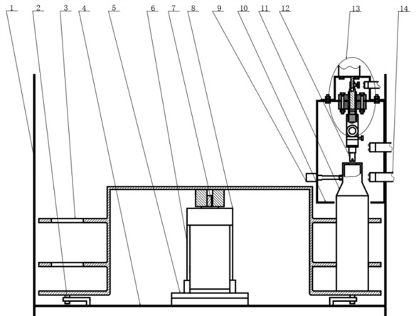
Fig. 3The schematic diagram of bottling positioning device: 1 – small-power-motors, 2 – fastening screw, 3 – joint bolt, 4 – proximity switch, 5 – generator bracket, 6 – fastening bolt, 7 – service bolt, 8 – support frame, 9 – guide block, 10 – thread rod, 11 – guiding bar, 12 – connection block, 13 – tee, 14 – water pipe, 15 – bolt hole alignment, 16 – proximity switch, 17 – water jet nozzle
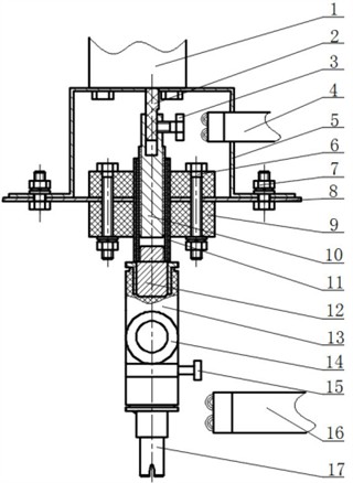
Fig. 4Sampling bottle cap: 1 – rubber gasket, 2 – plastic stopper, 3 – spring, 4 – upper bottle cap, 5 – lower bottle cap, 6 – bottle, 7 – leak-proof stopper, 8 – spring seat
3.2. The receiving end structural composition
The structure of the receiving end is shown in Fig. 5. Its function is to judge whether the runoff generated by rainfall meets the sampling conditions through external flowmeter and tilt-activated switch, and to transmit this information to the collection end controller. During rainfall, when the sampling condition is reached, the receiving end controller receives the acquisition signal sent by the collection end, and turns on or off the peristaltic pump for sampling as required. Sampling shall be carried out when the runoff of the next rainfall meets the sampling criteria. At the same time, the receiving end sends the data on the total runoff volume to the collection end at fixed time intervals. Since the external flowmeter at the collecting end is only used to judge whether the runoff volume meets the sampling criteria, its accuracy requirement is not high. Thus, calibration is unnecessary.
Fig. 5Schematic diagram of the receiving end
3.3. Operating principle
The system operates as follows. During sampling, status information is input via the human-machine interface, specifically the EzUIVXX_043_V11 color LCD module, to set parameters and monitor the sampling state. After setup, personnel can leave. When the rainfall does not meet the sampling conditions, the system enters standby mode. When the rainfall reaches the sampling conditions, the sampling bottle is positioned and the positioning information is recorded. The proximity switch 14 detects whether the sampling bottle is within its detection range. If the sampling bottle enters the detection range of proximity switch 14 and the travel switch 9 is also triggered at the same time, it indicates that the positioning of the sampling bottle is accurate. At this time, the small motor on the bottle filling device rotates forward to extend the water spray nozzle. When the proximity switch 16 is triggered, it indicates that the water spray nozzle has been fully inserted into the sampling bottle's mouth, thereby enabling the sampling operation. Subsequently, a signal to activate the peristaltic pump is transmitted to the collection end through the RS485 communication module for pumping. The water flows through the pipeline and enters the container through a spray nozzle. The turbine flowmeter begins to record the flow rate, while the real-time clock records the start time of sampling. When the set number of sampling pulses is reached, corresponding to the filling of one bottle, the collection end returns a signal to the collection end, turns off the peristaltic pump, and queries the real-time clock to record the completion information of sampling. At the same time, the small motor reverses to retract the water spray nozzle, and then the DC motor continues to rotate, entering the next positioning and bottle filling cycle. Each time the bottle is changed, the DC motor rotates 15°. After completing the set sampling targets, the rainfall runoff sampler stops sampling.
4. System control
4.1. The collection end control device
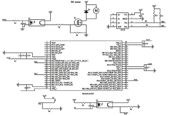
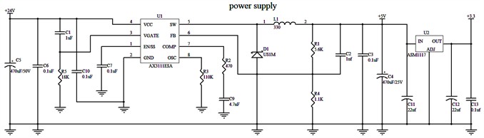
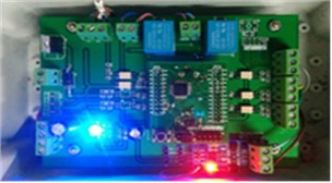
The control unit mainly monitors and give feedback on the sampling bottle position and turbine flowmeter counting. The hardware includes a power module circuit, a turbine flowmeter circuit, a sensor circuit, an MCU, etc. The switching power supply is supplied by a 220 V AC power supply to provide 24 V DC voltage. The 24 V DC voltage is regulated to 5 V and 3.3 V using voltage regulator chip AX3111ESA and ASM3117 to supply power to the proximity switch, travel switch and SCM. The STM32F103C8T6 MCU is selected as the DC motor control chip, while the AT24C08 internal processor chip stores positioning information and sampling quantity. The position information of the sampling bottle is monitored by the sensor control circuit through proximity and travel switches, and this information is fed back to the SCM to complete the positioning detection. The turbine flowmeter is powered by the 5 V DC power supply provided on the control panel. When water flows through the turbine flowmeter, a pulse signal is generated. The output current of the turbine flowmeter is about 10 mA. Through photoelectric isolation and level conversion using an optocoupler, the number of pulses is recorded by detecting the rising edge of the pulse through the SCM to obtain the flow rate. The main control circuit of the collection end and the real object are shown in Fig. 6.
Fig. 6The main control circuit and physical picture of the collection end. Photos by Yang Main, Fuling, Chongqing, May 2025
4.2. The receiving end control device
The receiving end can judge whether the runoff meets the sampling conditions. If the sampling conditions are not met, the sampling shall be suspended, and the uncompleted sampling shall be continued when the next rainfall comes. The control system at the receiving end receives information via an RS485 module, analyzes the information, and then controls peristaltic pump operation via relay switching. Meanwhile, it completes the self-inspection of the communication line and the runoff size and total runoff volume recognition via the flow sensor. The main control circuit and real object of the receiving end are shown in Fig. 7.
Fig. 7The main control circuit and real object of the receiving end. Photos by Yang Main, Fuling, Chongqing, May 2025
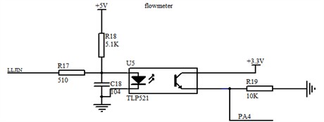
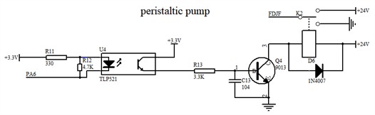
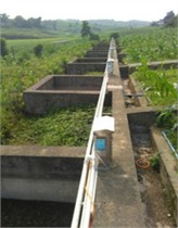
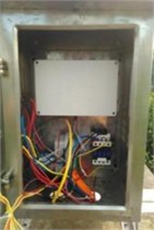
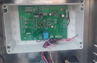
Fig. 8Flow chart of the sampler system
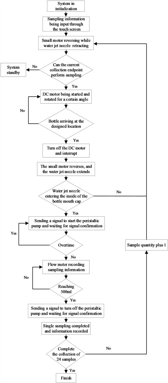
4.3. System program flow
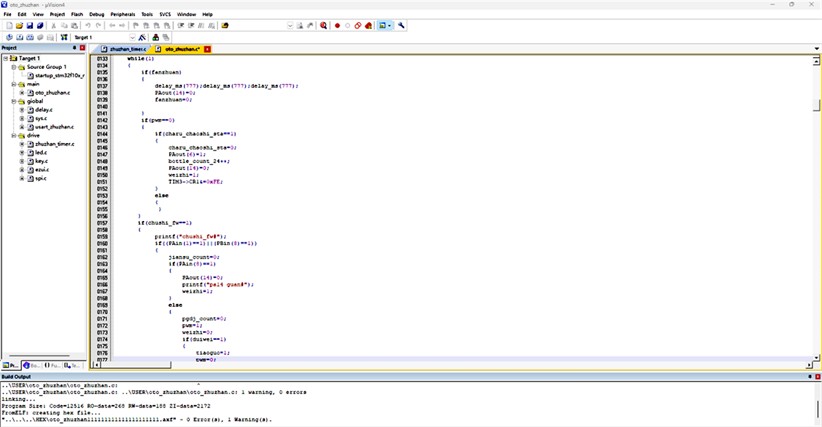
This kind of SCM uses C language programming with Keil software for control program development [17, 18]. A programmable controller is used to supervise the control system of the sampler, and the main functions include the control logic for bottle change of the DC motor controlled by PWM [19, 20]. The relay controls the small motor’s rotation of the threaded rod to supervise the up-and-down telescopic control logic of the spray nozzle. Additionally, it facilitates the transmission and recording of sampling information. The system can set the size and time interval of each sampling volume by inputting the sampling setting through the touch screen after initialization. When the touch screen is set, the sampler enters the working state and starts sampling until 24 samples are achieved. It develops a self-checking program for the sampler to correct errors caused by communication interruptions or other hardware failures. Equipped with self-checking function, the sampler can perform self-correction or shutdown in case of hardware errors. The workflow of the sampler is shown in Fig.8 and part of the control program is shown in Fig. 9.
Fig. 9Control program interface
5. Error test
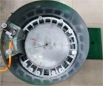
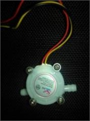
The turbine flowmeter (Model: YF-S401) used in the sampler is shown in Fig. 10. This device offers advantages such as simplified control, accurate flow sampling, and low cost. Considering the shutdown delay of the peristaltic pump, when the fluid state does not change significantly and the turbine flowmeter operates within its linear region, the shutdown delay of the peristaltic pump is mainly generated by the relay’s closing time and the inertia of the pump. Therefore, when the peristaltic pump is logically shut down, there will still be 5-9 ml of water flow overflowing. Correcting this value in the program will improve the sampling accuracy. When the flow rate reaches the set value, a shutdown command is sent to deactivate the peristaltic pump. Since each container has a volume of only 500 ml, it is necessary to determine whether the accumulated flow rate has reached 500 ml. If the target volume has not been reached, the peristaltic pump is temporarily turned off according to the previously set sampling interval time. If the sampling interval time is reached, the pump is restarted, and the sampling process is repeated until 500 ml is collected.
Fig. 10The physical picture of turbine flowmeter. Photo by Yuli Ouyan, Southwest University, Chongqing, May 2025
5.1. Flow meter response equation
The turbine flowmeter reflects the measured flow rate based on the turbine speed. The relationship between turbine speed and flow rate can be expressed as [21]:
where is the instrument constant; is the starting flow, obtained through calibration.
5.2. Theoretical calculation of intrinsic instrument constants of turbine flowmeter
The turbine speed changes with the flow rate; that is, a higher flow rate results in a higher turbine speed. The rotational speed of the turbine is converted into an electrical pulse signal of corresponding frequency by a magnetic-electric conversion device. After amplification by a preamplifier, the signal is sent to a display instrument for counting and display. Therefore, the instantaneous flow rate and cumulative flow rate can be calculated based on the number of pulses per unit time and the total cumulative number of pulses. The intrinsic instrument coefficient of the turbine flowmeter is mainly related to the structural parameters of the turbine sensor and can be calculated as [22]:
where , , , , , , and are constants related to the turbine structure.
The working principle of a turbine transmitter is that when the fluid flows along the axis of the pipeline and impacts the turbine blades, there is a response equation for the flow meter:
where is the flow rate flowing through the transmitter; is the frequency of the electrical pulse; is the instrument coefficient.
5.3. Sampling error calibration
The output pulse frequency of a flowmeter is directly proportional to the flow rate. The larger the flow rate, the higher the output frequency. However, the time required for water to flow through a unit volume decreases with increasing flow rate. The accuracy of turbine flowmeter generally ranges from 0.1 % to 0.5 %. When operating within the linear flow range, even if the flow rate changes, the accuracy of the cumulative flow rate will not decrease. Furthermore, the reproducibility of the turbine flowmeter can reach 0.05 % in a short period [23]. Therefore, theoretically, under constant external conditions, the number of pulses corresponding to each 500 ml water sample should be a constant. The calibration of the turbine flowmeter at the collection end is shown in Table 1.
Table 1Calibration of turbine flowmeter
Measurement data | Group | |||||||
A | B | C | D | E | F | G | H | |
Number of pulses (N) | 1331 | 1357 | 1347 | 1334 | 1333 | 1329 | 1339 | 1336 |
Time (s) | 45 | 44 | 46 | 47 | 46 | 45 | 46 | 46 |
Volume (ml) | 512 | 522 | 516 | 513 | 513 | 511 | 515 | 514 |
Error (%) | +2.40 | +4.40 | +3.20 | +2.60 | +2.60 | +2.20 | +3.00 | +2.80 |
According to Table 1, the number of pulses generated by each 500 ml water sample is approximately 1300, and the errors are all positive. The main reason is that there is a certain delay in the shutdown of the peristaltic pump at the receiving end. The actual flow rate, determined by measurement with a graduated cylinder, also exhibits has a certain deviation. This error will be corrected after the sampler is installed by adjusting the pulse count set in the control program, yielding the reference number of pulses required for a 500 ml water sample obtained here.
5.4. Sampling error measurement
In order to verify the feasibility of the sampler and its sampling accuracy, experimental validation of the collection end’s sampling error needs to be conducted after the overall design of the sampler is completed [24]-[25]. Since the external flowmeter at the receiving end is only used to judge the size of the runoff, its precision requirements are not high, so no accurate measurement is performed. It was found during the experimental validation that when the turbine flowmeter is working but no water flows through, the output occasionally remains stuck in a high state. Therefore, it is more reliable to record the number of pulses by external interruption.
Table 2Error measurement results
Measurement data | Group1 | |||||||
1 | 2 | 3 | 4 | 5 | 6 | 7 | 8 | |
Number of pulses (N) | 1308 | 1306 | 1311 | 1308 | 1314 | 1307 | 1306 | 1310 |
Time (s) | 44 | 44 | 45 | 46 | 44 | 45 | 46 | 46 |
Volume (ml) | 503.0 | 509.4 | 506.9 | 492.9 | 494.3 | 498.2 | 493.3 | 509.5 |
Error (%) | +0.60 | +1.88 | +1.38 | –1.42 | –1.14 | –0.36 | –1.34 | +1.90 |
Measurement data | Group2 | |||||||
1 | 2 | 3 | 4 | 5 | 6 | 7 | 8 | |
Number of pulses (N) | 1312 | 1309 | 1311 | 1306 | 1307 | 1307 | 1311 | 1308 |
Time (s) | 44 | 44 | 44 | 45 | 44 | 46 | 45 | 45 |
Volume (ml) | 508.0 | 505.2 | 495.9 | 491.9 | 500.3 | 506.4 | 503.3 | 505.5 |
Error (%) | +1.60 | +1.04 | –0.82 | –1.62 | +0.06 | +1.28 | +0.66 | +1.10 |
Measurement data | Group3 | |||||||
1 | 2 | 3 | 4 | 5 | 6 | 7 | 8 | |
Number of pulses (N) | 1310 | 1312 | 1309 | 1310 | 1310 | 1309 | 1311 | 1307 |
Time (s) | 44 | 46 | 44 | 45 | 44 | 44 | 46 | 44 |
Volume (ml) | 505.6 | 507.2 | 502.3 | 499.8 | 498.1 | 502.9 | 505.3 | 500.7 |
Error (%) | +1.12 | +1.44 | +0.46 | –0.04 | –0.38 | +0.58 | +1.06 | +0.14 |
In addition, the power line and signal line of the turbine flowmeter shall be isolated; otherwise, a great error will be caused to disturb the stroke and affect the sampling accuracy. When the fluid state does not change greatly and the turbine flowmeter operates within its linear range, the shutdown delay of the peristaltic pump is primarily caused by the actuation time and inertia of the relay. Therefore, approximately 5 mL of water continues to flow even after logical pump shutdown. The experimental process has been conducted to correct the pulse value to improve the sampling accuracy. After adjusting the pulse count for each 500 mL water sample to 1292, experiments are conducted in three groups with a total of 72 water samples. Eight bottles are randomly selected from each group for measurement, and the water samples are weighed. The actual sampling error measurement results are shown in Table 2.
It can be seen from Table 2 that the sampling duration for the 24 experimental samples (randomly selected from three groups) ranged from 44 s and 46 s, with the corresponding pulse count varying between 1306 and 1314. When the cumulative sampled volume reaches 500 ml, i.e. the sampling weight reaches 500g, the sampling accuracy of the sampler can be controlled within ± 2 % through calculation. The sampler can meet the sampling requirements and can ensure the sampling accuracy after repeated tests. Good cooperation is achieved between the collection end and the receiving end of the sampler, and stable working performance is achieved in field farmland. Furthermore, the automatic sealing function of the sampling bottle cap performed reliably in the experiment, meeting the overall usage requirements of the equipment.
6. Conclusions
This paper studies and designs a small farmland rainfall runoff sampler in remote or inaccessible farmland. Through the control of the STM32 MCU, the sampler can accurately collect the runoff generated by rainfall without any human intervention. The receiving end of the system is simple in design, operating by receiving and sending signals from the collection end to actuate the start-stop cycles of the peristaltic pump. The collection end of the system is designed to ensure precise positioning of the sampling bottle during operation to facilitate the smooth sampling. During sampling, the pulse counter of turbine flowmeter is used to realize quantitative collection of 500 ml rainwater with minimal error, meeting the requirement for accurate sampling. In actual multiple tests, the control system operates reliably, and the sampling error can be controlled within ± 2 %. The rainfall runoff sampler has a simple composition and is convenient for productization, and can avoid the risk of manual sampling in bad weather in the field. Meanwhile, its lightweight design simplifies field transportation. The control system of the sampler reduces the number of braking components and sensors, lowering production costs and enhancing practicality. In order to reduce the uncertainty in pollutant concentration detection in rainwater, the sampling bottle cap is designed with anti-volatilization, effectively ensuring the accuracy of subsequent chemical detection and analysis. The control system reduces the number of braking components and sensors, lowering production costs and enhancing practicality. To reduce uncertainty in pollutant concentration detection in rainwater, the sampling bottle cap features a vapor-proof design, effectively ensuring the accuracy of subsequent chemical detection and analysis. During the long-term operation of the sampler in the field, factors that have a certain impact on sampling accuracy have been discovered, such as delayed shutdown of the peristaltic pump, unstable transmission of RS485 communication signals, and positioning errors caused by insufficient mechanical processing accuracy. Although optimization has been carried out in the control program, the equipment needs further improvement to achieve higher sampling accuracy in the later stage. In order to enhance the applicability of this sampler for sampling in specific regions, a wireless communication module will be added in the future to achieve remote control.
References
-
H. Li, “Research on prevention and control measures for non point source pollution in agriculture,” (in Chinese), Hebei Agricultural Machinery, Vol. 329, No. 15, pp. 163–165, Nov. 2023, https://doi.org/10.15989/j.cnki.hbnjzzs.2023.15.031
-
A. Cao, Y. Yao, and C. Chen, “Research on pesticide registration, residue status, and safe use in vegetable in China,” (in Chinese), Jiangsu Agricultural Sciences, Vol. 51, No. 22, pp. 8–14, Nov. 2023, https://doi.org/10.15889/j.issn.1002-1302.2023.22.002
-
J. Gao, Z. Wang, and J. Zhao, “Research on sampling method in rainfall Runoff,” (in Chinese), Journal of Tianjin University of Technology, Vol. 34, No. 4, pp. 45–49, Aug. 2018, https://doi.org/10.3969/j.issn.1673-095x.2018.04.010
-
K. Huang, “Research on pesticide registration, residue status, and safe use in vegetables in China,” (in Chinese), Xi’an University of Architecture and Technology, Jun. 2024, https://doi.org/10.27393/d.cnki.gxazu.2024.001040
-
R. Weerasinghe, A. S. Pannila, M. K. Jayananda, and D. U. J. Sonnadara, “Automated rain sampler for real time ph and conductivity measurements,” in Proceedings of the Technical Sessions, Institute of Physics Sri Lanka, No. 31, pp. 39–44, Jan. 2015.
-
P. Fučík, M. Kaplická, T. Kvítek, and J. Peterková, “Dynamics of stream water quality during snowmelt and rainfall – Runoff events in a small agricultural catchment,” CLEAN – Soil, Air, Water, Vol. 40, No. 2, pp. 154–163, Nov. 2011, https://doi.org/10.1002/clen.201100248
-
C. Su, D. Hou, S. Zhao, X. Li, Z. Yuan, and D. Yu, “Remote control rain sampler for rainfall runoff collection,” Water Supply, Vol. 20, No. 2, pp. 644–651, Mar. 2020, https://doi.org/10.2166/ws.2019.200
-
A. A. Colussi et al., “Cost-effective off-grid automatic precipitation samplers for pollutant and biogeochemical atmospheric deposition,” Atmospheric Measurement Techniques, Vol. 17, No. 12, pp. 3697–3718, Jun. 2024, https://doi.org/10.5194/amt-17-3697-2024
-
T. Audoux et al., “Automatic sequential rain sampling to study atmospheric particulate and dissolved wet deposition,” Atmospheric Environment, Vol. 295, p. 119561, Feb. 2023, https://doi.org/10.1016/j.atmosenv.2022.119561
-
M. Gröning, H. O. Lutz, Z. Roller-Lutz, M. Kralik, L. Gourcy, and L. Pöltenstein, “A simple rain collector preventing water re-evaporation dedicated for δ18O and δ2H analysis of cumulative precipitation samples,” Journal of Hydrology, Vol. 448-449, No. 41, pp. 195–200, Jul. 2012, https://doi.org/10.1016/j.jhydrol.2012.04.041
-
Q. Zhang, M. Wang, and S. Zhang, “Development and application of automated sampling technology for urban rainfall Runoff monitoring,” (in Chinese), Environmental Engineering, Vol. 38, No. 4, pp. 141–144, Nov. 2023, https://doi.org/10.13205/j.hjgc.202004025
-
X. Xu, J. Lin, and D. Ye, “Design of drawer type slope Runoff sampler,” (in Chinese), Fujian Agricultural Machinery, No. 3, pp. 30–34, Sep. 2015.
-
H. Zhu, “Research on a mobile phone remote-controlled water sampler,” (in Chinese), Changchun University of Technology, Jun. 2018.
-
W. Zhu and S. Guo, “Analysis of multi-sensor data fusion positioning technology,” (in Chinese), Electronic Technology, No. 3, pp. 7–9, May 2025, https://doi.org/10.3969/j.issn.1000-0755.2025.03.003
-
Y. Deng, Y. Liu, and Y. Wu, “Design of intelligent home temperature control system based on MCU,” (in Chinese), Technological Innovation and Productivity, No. 7, pp. 101–102, Jul. 2022, https://doi.org/10.3969/j.issn.1674-9146.2022.07.101
-
Y. Gao, Q. Zhao, and S. Han, “Matching design of limit switches and proximity switches in a CNC system,” (in Chinese), Machine tool and hydraulic, Vol. 43, No. 4, pp. 141–143, Feb. 2015, https://doi.org/10.3969/j.issn.1001-3881.2015.04.045
-
G. Ren and G. Zhang, “Design and implementation of a smart home information instrument based on STC12,” Modern Electronic Technology, Vol. 40, No. 8, pp. 69–72, Apr. 2017, https://doi.org/0.16652/j.in.1004-373x. 2017.08.020
-
J. Sheng, C. Guo, and H. Yang, “Design of a three-phase AC charging pile control system based on STM32,” (in Chinese), Electric Measuring and Instrumentation, Vol. 57, No. 16, pp. 125–129, Nov. 2020, https://doi.org/10.19753/j.issn1001-1390.2020.16.021
-
X. Miao, S. Wang, and J. Guo, “Fuzzy WMR-PID algorithm-based speed regulation control of brushless DC motor,” (in Chinese), Chinese Journal of Engineering Machinery, Vol. 21, No. 1, pp. 38–42, Feb. 2023.
-
Y. Shi, “Simulation analysis of DC motor control algorithm based on fuzzy PID control,” (in Chinese), Electronic Manufacturing, No. 13, pp. 6–9, Jul. 2020, https://doi.org/10.16589/j.cnki.cn11-3571/tn.2020.13.002
-
X. Zhong, Y. Wu, and S. Tian, “Multiphase flow rate measurement with turbine flow meter,” (in Chinese), Instrumental Instrumentation Journal, Vol. 23, pp. 858–859, Dec. 2002, https://doi.org/10.19650/j.cnki.cjsi.2002.s2.177
-
S. Wang, T. Zhang, and J. Wang, “Research on dynamic flow measurement method based on turbine flowmeter,” Measurement and Control Technology, Vol. 31, No. 11, pp. 24–27, Nov. 2012, https://doi.org/10.19708/j.ckjs.2012.11.006
-
Y. Wang, “Intelligent gas turbine flowmeter measurement accuracy: influencing factors and mitigation measures,” (in Chinese), Gas and Heat, Vol. 37, No. 10, pp. 17–19, Oct. 2017.
-
H. Bian, D. Huang, and X. Dong, “Analysis and experiment on factors affecting the relative error of indication of turbine flowmeter,” (in Chinese), Gas and Heat, Vol. 45, No. 7, pp. 53–55, Jul. 2025, https://doi.org/10.13608/j.cnki.1000-4416.2025.07.010
-
J. Zhang, “Study on sampling quality control in water environment monitoring,” (in Chinese), Water Science and Engineering Technology, No. 3, pp. 35–38, Jun. 2025, https://doi.org/10.19733/j.cnki.1672-9900.2025.03.09
About this article

This work is supported by the Chongqing Municipal Education Commission Science and Technology Research Project (JQN202302829) and the Chongqing Vocational Education Teaching Reform Research Project Fund (Z233053).
The datasets generated during and/or analyzed during the current study are available from the corresponding author on reasonable request.
Yang Ma was responsible for the design and writing of the entire article, Huimei Zhang was responsible for guiding and revising the article, Yuli Ouyang was responsible for experimental testing, Yue Zhang was responsible for grammar checking.
The authors declare that they have no conflict of interest.
