Abstract
Modal characteristics are the key basis for evaluating the vibration and noise response of the carriage frame. The finite element technology was used to simulate and calculate the models under no-load and full-load conditions respectively, and the first four modal shapes and natural frequencies under no prestress and prestress conditions were obtained. To ensure that the first natural frequency under full-load conditions is not less than 10 Hz, the carriage frame was lightened based on the multi-objective optimization method. The thicknesses of different components were established as design variables, and the optimal solution meeting the boundary conditions was obtained through the particle swarm algorithm. The results show that through the lightweight design, the model weight can be reduced by 4 % under the premise of meeting the modal standards, providing a scientific method for the targeted optimization of the carriage frame.
Highlights
- The finite element technology was used to simulate and calculate the models under no-load and full-load conditions respectively, and the first four modal shapes and natural frequencies under no prestress and prestress conditions were obtained.
- To ensure that the first natural frequency under full-load conditions is not less than 10 Hz, the carriage frame was lightened based on the multi-objective optimization method.
- The thicknesses of different components were established as design variables, and the optimal solution meeting the boundary conditions was obtained through the particle swarm algorithm.
1. Introduction
Against the backdrop of increasingly severe global energy crisis and environmental problems, energy conservation and emission reduction in the transportation industry have become a core issue in the sustainable development strategies of various countries. Therefore, lightweight design has emerged as a key technical path for the upgrading of transportation equipment [1-3]. The lightweight design of carriage frames needs to achieve the goal of weight reduction through the reorganization of structural topology and dimensional parameters on the premise of meeting performance indicators such as strength, stiffness, and dynamic characteristics [4]. However, traditional design methods rely heavily on empirical formulas and physical tests, which have problems such as long research and development cycles, high costs, and low precision in performance matching. Especially in terms of dynamic performance, carriage frames need to withstand complex vibration loads during operation. If the modal characteristics of the structure are not properly controlled during the lightweight process, it may lead to resonance, triggering risks such as structural fatigue failure and reduced ride comfort.
The development of modal simulation technology provides an effective means to solve the above contradictions [5, 6]. Modal analysis reveals the laws of structural dynamic characteristics by solving parameters such as the natural frequency, modal shape, and damping ratio of the structure, providing a theoretical basis for avoiding resonance and optimizing vibration response [7]. With the iterative upgrading of Finite Element Analysis (FEA) software, modal simulation can already achieve high-precision prediction of dynamic characteristics of complex structures, which is much lower than the cost and cycle of physical tests. Based on the above background, this paper takes the typical intercity train carriage frame as the research object and proposes a lightweight design method integrating high-precision modal simulation and multi-objective optimization. An optimization model with weight reduction rate and first-order natural frequency as objectives is constructed, and an improved particle swarm optimization algorithm is used to solve the optimal scheme. The research results are expected to provide new ideas and methods for structural lightweight design in fields such as rail transit and commercial vehicles, promoting the industry towards a more efficient, energy-saving, and safe direction.
2. Establishment of the finite element model and modal analysis
2.1. Model simplification and mesh generation
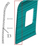
In the lightweight design of train carriage frames based on modal simulation, the simplification and meshing of the finite element model are key links connecting the physical structure and numerical calculation, which directly affect the accuracy and efficiency of the simulation results [8]. On the premise of retaining the core mechanical properties of the structure, a balance between high accuracy and high efficiency should be achieved through scientific simplification and reasonable division. The structure of the carriage frame is complex, including various components such as longitudinal beams, crossbeams, connectors, and stiffeners. Direct modeling will lead to a sharp increase in the number of elements and high calculation costs. Model simplification needs to retain the geometric features that play a leading role in structural stiffness and modal characteristics, and eliminate minor details. In terms of geometric simplification, a half-model can be established for symmetric parts, as shown in Fig. 1(a). Boolean operations can be used to delete them or replace them with equivalent geometric structures, as shown in Fig. 1(b). The welding groove of the carriage frame can be simplified into a weld element, such as the COMBIN14 spring element to simulate the welding stiffness, so as to avoid mesh distortion caused by tiny features. For detachable connections (such as bolted connections), if their stiffness is much greater than that of adjacent components, MPC (Multi-Point Constraint) elements can be used to simulate rigid connections. If connection flexibility needs to be considered, the contact stiffness can be defined through the COMBIN39 nonlinear spring element. Material simplification needs to be based on the homogenization assumption, and the heterogeneous materials of the frame should be converted into a single material property according to the principle of equivalent stiffness. The simplification of boundary conditions should be combined with actual working conditions. In modal analysis, the carriage frame is connected to the bogie through air springs, and elastic support can be used for simulation instead of rigid fixation to truly reflect the constraint state of the structure.
Fig. 1Model simplification and mesh processing
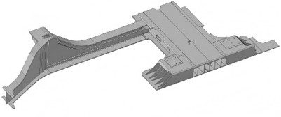
a) Symmetric semi-model
b) The simplified structures
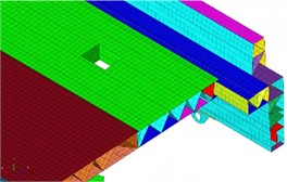
c) The division of shell elements
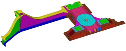
d) The hybrid of shell and solid elements
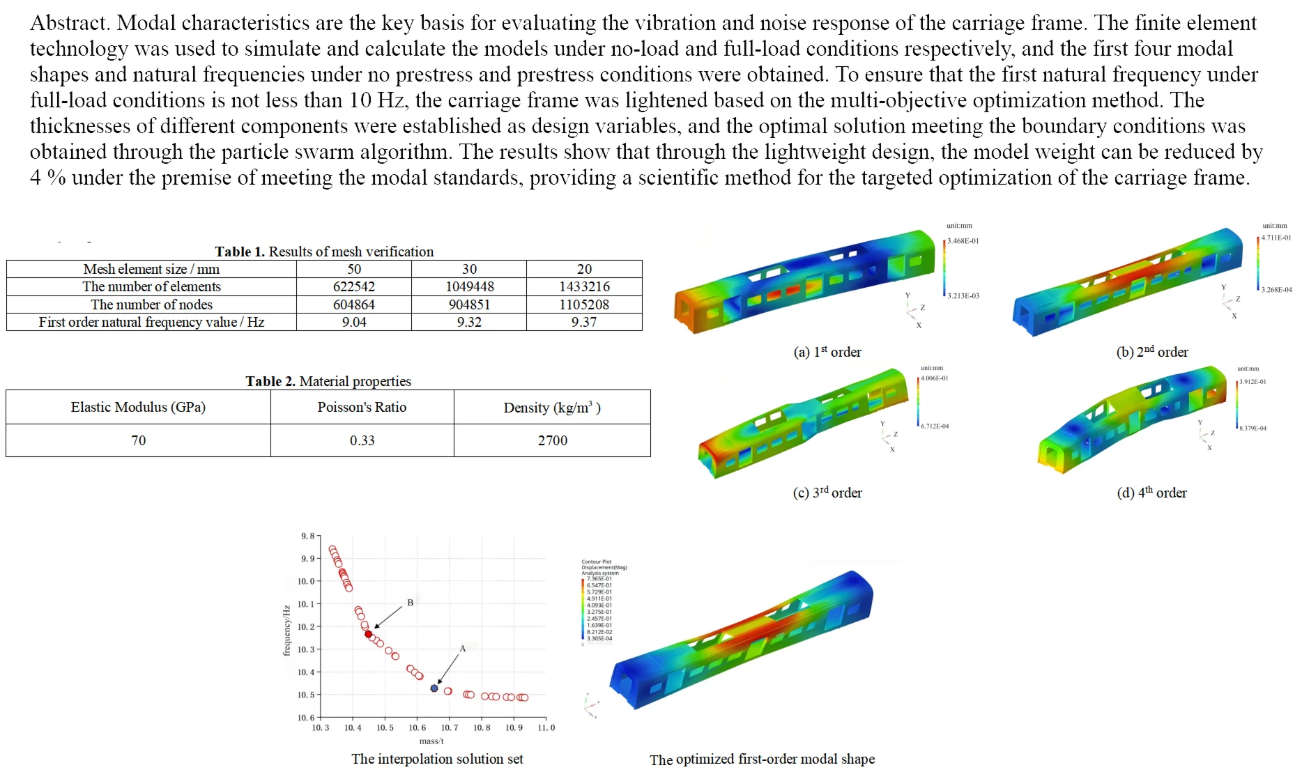
Meshing is the process of discretizing the simplified model into a finite number of elements, and its quality has a significant impact on the calculation accuracy. The meshing of the carriage frame needs to select the element type according to the structural characteristics. The main beam structure adopts shell elements (SHELL181) because it has both accuracy and efficiency in simulating thin plate parts, as shown in Fig. 1(c). For local thick-walled structures, such as the connection nodes between crossbeams and longitudinal beams, solid elements (SOLID186) can be used, and the sweep meshing technology is used to ensure the directionality of the elements, as shown in Fig. 1(d). The selection of mesh size should be determined through convergence verification. First, divide the basic mesh with a larger size (50 mm), then gradually reduce the size (30 mm, 20 mm) and calculate the first-order natural frequency. When the deviation between two adjacent results is less than 2 %, the corresponding size is the optimal value. Taking the first order natural frequency () under full load condition as the calculation target, the verification results of the mesh are presented in Table 1. Evidently, when the element size is set to 30 mm, the accuracy requirements can be fulfilled.
Table 1Results of mesh verification
Mesh element size / mm | 50 | 30 | 20 |
The number of elements | 622542 | 1049448 | 1433216 |
The number of nodes | 604864 | 904851 | 1105208 |
First order natural frequency value / Hz | 9.04 | 9.32 | 9.37 |
For stress concentration areas, local encryption technology should be adopted, and transition meshes should be used to avoid calculation oscillations caused by sudden changes in elements. Adaptive meshing technology is used to automatically adjust the element density according to the stress gradient, and large-size meshes are used in low-stress areas. The mesh partitioning technology is utilized to split the frame into components such as longitudinal beams, crossbeams, and end walls, and different modules are divided separately and then assembled, which reduces the calculation time for overall mesh generation. For linear problems such as modal analysis, reduced integration elements can be enabled to reduce the number of element degrees of freedom on the premise of ensuring accuracy. The material of the carriage frame is aluminum alloy. The relevant material properties are presented in Table 2.
Table 2Material properties
Elastic modulus (GPa) | Poisson’s ratio | Density (kg/m3) |
70 | 0.33 | 2700 |
2.2. Modal calculation results and analysis
2.2.1. Modal analysis without prestress (No-load)
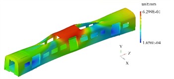
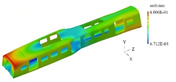
The first four mode shapes and their contour plots under the condition of no prestress are shown in Fig. 2. It can be seen that in the state without prestress, the modal characteristics of the carriage frame are determined solely by its own structural stiffness and mass distribution. The first four mode shapes mainly reflect the overall bending, torsion and local deformation features.
The first mode shape is mainly characterized by symmetrical bending along the longitudinal direction, with the maximum deflection occurring in the middle part of the frame. The ends are the regions with the smallest displacement, and the middle part gradually transitions to the region with the largest displacement. The upper and lower surfaces are symmetrically distributed, reflecting the typical characteristics of a simply supported beam bending. There is no obvious distortion at the connection nodes of the longitudinal and transverse beams. The second mode shape is characterized by torsion around the longitudinal center axis, with the two ends of the frame showing a tendency to rotate in opposite directions. The mode shape contour plot shows that the corner area at one end is red (maximum positive torsional displacement), and the diagonal area is blue (maximum negative torsional displacement). The middle section (midpoint in the length direction) forms an approximate neutral axis, with a smooth color transition. Due to the higher stiffness of the reinforcing ribs, the color change amplitude in this area is smaller than that of the main beam structure. The third modal shape is mainly characterized by bending deformation along the transverse direction, with the frame bulging on one side and concaving on the other. In the modal shape contour plot, the middle area on the bulging side is red (maximum lateral displacement), and the corresponding area on the concaving side is blue. The longitudinal beams undergo a slight "S" shape deformation under the lateral force, and the end wall area has a smaller displacement due to rigid constraints. The fourth modal shape is concentrated in the weak parts of the frame, such as the area where the air conditioning is installed on the roof or the suspension structure under the floor. In the modal shape contour plot, isolated high-displacement red areas appear in local regions, while the surrounding structure shows a smooth color transition. This reflects the weak coupling characteristics between the local modal and the overall structure. The displacement amplitude of the main beams is less than 1/5 of that in the local areas.
Fig. 2The first four modal shapes under the condition of no prestress
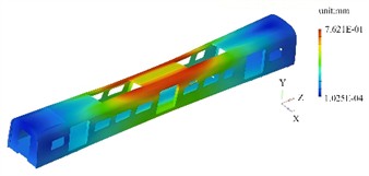
a) 1st order
b) 2nd order
c) 3rd order
d) 4th order
2.2.2. Modal analysis with prestress (full load)
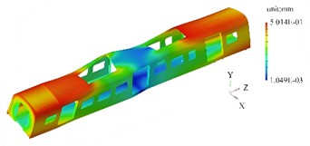
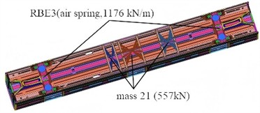
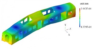
Under full-load conditions, RBE3 and MASS elements are respectively selected to simulate the connection mode and load of the suspension equipment, as shown in Fig. 3. The first four modal shapes and their contour plots under full load are shown in Fig. 4. Prestress alters the stiffness distribution of the frame, resulting in differences in modal shapes compared to the state without prestress, especially in high-stress areas.
Fig. 3Analysis model under full load conditions
In the first modal, the overall bending trend is consistent with that without prestress, but the gradient distribution of the modal shape contour plot is steeper. At the connection points of the beams with concentrated prestress, the maximum displacement point shifts about 5 % to 10 % towards the side with lower stress, indicating that prestress causes asymmetry in the stiffness distribution of the structure. The second modal is a torsional modal, with the torsional center shifting towards the side with greater prestress. Due to residual stress at the welded joints, small red spots appear, indicating additional local deformation during torsion in this area. The third modal is a lateral bending mode, with the high-displacement area shrinking and shifting towards the lower part of the frame. This is because the floor, after being subjected to the constant load prestress, has a relatively increased stiffness in the lower structure. In the fourth modal, the local vibration areas shift to the parts where prestress is more released, such as the corners of the end walls and side walls. Prestress reduces the coupling degree between local modes and the overall structure’s vibration.
Fig. 4The first four modal shapes with prestress
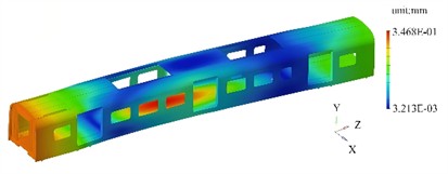
a) 1st order
b) 2nd order
c) 3rd order
d) 4th order
Table 3Natural frequencies under preloaded and non-preloaded conditions
Order | 1 | 2 | 3 | 4 |
Natural frequency under preloaded condition / Hz | 9.32 | 14.66 | 20.09 | 29.97 |
Natural frequency under non-preloaded condition / Hz | 12.25 | 15.13 | 22.31 | 32.48 |
Natural frequencies under preloaded and non-preloaded conditions are shown Table 3. It can be seen that the first natural frequency under prestressed state is 9.32 Hz. According to the Chinese railway industry standard (TB/T 3115-2005), it is known that it does not meet the minimum limit of 10 Hz as required. Moreover, low-frequency vibration is prone to be close to the natural frequency of the equipment installed under the train body, thereby triggering resonance. Resonance will significantly amplify the vibration amplitude, leading to accelerated wear and performance degradation of the equipment, seriously affecting the safety, reliability and durability of the vehicle. To avoid resonance and meet the standard requirements, the first natural frequency under prestressed state and the frame mass will be taken as the two main optimization objectives.
To determine the influence of contact stiffness on the natural frequency of the carriage frame, the frequency deviation was calculated within the stiffness variation range of –20 % to 20 %, as shown in Table 4. According to the China Railway Industry Standard (TB/T 2841-2010), the initial stiffness of the air spring is defined as 1176 kN/m. Results show that a 20 % change in contact stiffness corresponds to a change of approximately 4 % in the first order natural frequency.
Table 4The influence of contact stiffness on natural frequency
Initial stiffness / (kN/m) | Initial first order natural frequency / Hz | Rate of stiffness change / % | The corresponding natural frequency / Hz | Rate of natural frequency change / % |
1176 | 9.32 | –20 | 8.95 | –3.97 |
–10 | 9.13 | –2.04 | ||
0 | 9.32 | 0 | ||
10 | 9.53 | 2.25 | ||
20 | 9.72 | 4.29 |
3. Lightweight design and analysis
3.1. The setting of design variables and solution methods
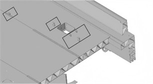
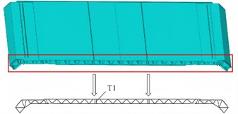
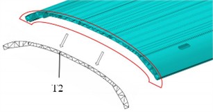
In the lightweight design of the carriage frame, the selection of design variables should closely revolve around the optimization goal of structural dynamic characteristics. By combining the characteristics of the first four modal shapes and the influence of prestress on stiffness distribution, the dual goals of increasing the weight reduction rate and achieving the first natural frequency standard (≥ 10 Hz) can be realized. For this purpose, three different thickness dimensions are defined as design variables, as shown in Fig. 5. The initial values of T1, T2 and T3 are 4.5 mm, 4 mm and 3.5 mm respectively, and their fluctuation range is ±20 % of the initial value. Through model analysis, it is known that the initial mass of the carriage frame is 10.9 t.
Fig. 5Selection of design variables
Lightweight design under the premise of meeting the first-order natural frequency is a multi-objective optimization problem, which requires optimizing multiple conflicting objective functions within the constraint set. Due to the heterogeneity of multi-objective functions, the rules between the same design variable and different optimization objectives are not the same, and there are contradictions among the optimization objectives. Therefore, it is impossible to achieve global optimization through a single solution.
3.2. Analysis and verification of modal characteristics
The extremum search of the optimization objective is conducted based on the particle swarm optimization (PSO) algorithm, that is, to ensure the minimum value of the mass and the maximum value of the natural frequency. In response to the multi-objective optimization requirement, the PSO algorithm is configured as follows: The population size is set to 30 particles. The inertia coefficient decreases linearly from 0.9 to 0.4. Both the cognitive coefficient and the social coefficient are set at 2.0. The penalty function is utilized to address the constraint of 10 Hz. The termination conditions are defined as 100 generations of iteration and convergence over 10 consecutive generations. The random seed is fixed at 42, and the design variables are the thicknesses of three crucial components. The objective is to obtain the minimum value of the mass. The interpolation points are shown in Fig. 6. It can be seen that the key inflection points are mainly Point A and Point B.
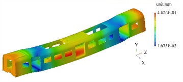
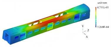
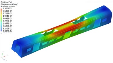
In typical optimization problems such as complex structure design, path planning, and system optimization in the engineering field, multi-objective collaborative optimization needs to be carried out under multiple constraints. Therefore, based on the theory of multi-objective optimization, it is necessary to obtain the Pareto optimal solution set to achieve a balanced compromise among the objectives. Each solution in this set represents a global non-dominated state, forming a Pareto frontier surface in the multi-dimensional objective space, thereby approaching the global optimum under constraints. Through extremum search, the optimized design variables T1, T2 and T3 were finally determined to be 4.06 mm, 4.17 mm and 3.22 mm respectively, with the corresponding mass and first-order natural frequency being 10.46 t and 10.25 Hz as at Point B. The modal shapes are shown in Fig. 7. The optimization results indicate that the weight can be reduced by 4 % while meeting the modal characteristics.
Fig. 6The interpolation solution set
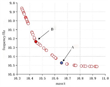
Fig. 7The optimized first-order modal shape
4. Conclusions
As the core structure for load-bearing and force transmission, the frame of the carriage requires a lightweight design that takes into account both dynamic performance and load-bearing capacity. This paper proposes a lightweight design method based on modal simulation analysis in response to the differences in modal characteristics under full load and no-load conditions. By constructing a finite element model of the frame through 3D modeling and finite element analysis, the first four natural frequencies and modal shapes under full load (rated load) and no-load conditions are solved respectively, and the weak areas with concentrated modal shape deformation are identified. With the core objective of lightweight (minimizing mass), the structure is optimized under the constraint of low-order natural frequencies under full load conditions. The results show that the mass of the frame is reduced by 4 % after optimization, meeting the requirements of full load conditions, and achieving a coordinated improvement in lightweight and dynamic performance.
References
-
N. Aliyeva, H. S. Sas, and B. Saner Okan, “Revolutionizing transportation composite structures: Lightweight, sustainable, and multi-scale hybrid design through waste tire-driven graphene, hemp fiber, and bio-based overmoulding,” Journal of Thermoplastic Composite Materials, Vol. 37, No. 9, pp. 2987–3011, Dec. 2023, https://doi.org/10.1177/08927057231222821
-
K. J. Kim and J.-W. Lee, “Light-weight design and structure analysis of automotive wheel carrier by using finite element analysis,” International Journal of Precision Engineering and Manufacturing, Vol. 23, No. 1, pp. 79–85, Dec. 2021, https://doi.org/10.1007/s12541-021-00595-x
-
C. Derkenne, S. Travers, R. Kedzierewicz, D. Jost, B. Prunet, and C. Martinaud, “Performances of iceless containers for lightweight transport of red cell concentrate units during military operations,” Transfusion Clinique et Biologique, Vol. 27, No. 2, pp. 98–102, Apr. 2020, https://doi.org/10.1016/j.tracli.2020.02.001
-
Y. Qiu, W. Xu, J. Fu, Z. Hu, and G. Cheng, “Dynamic analysis and design of novel distributed lump-parameters mounting system for marine power devices,” Ocean Engineering, Vol. 291, No. 1, p. 116143, Jan. 2024, https://doi.org/10.1016/j.oceaneng.2023.116143
-
M. Sohrabifard, M. Nategh, and M. Ghazavi, “Evaluation, calibration, and modal analysis for determination of contact stiffness between workpiece and components of milling fixture,” Proceedings of the Institution of Mechanical Engineers, Part B: Journal of Engineering Manufacture, Vol. 237, No. 12, pp. 1819–1835, Nov. 2022, https://doi.org/10.1177/09544054221138165
-
S. Gaygol and K. Wani, “Modal analysis of plate to analyze the effect of mass stiffeners using the Chladni plate approach,” Materials Today: Proceedings, Vol. 72, No. 3, pp. 1314–1321, Jan. 2023, https://doi.org/10.1016/j.matpr.2022.09.305
-
X. Li, D. Zhao, H. Zhai, M. Chen, and T. Zhang, “Modal analysis of circular arches in rectangular coordinate system,” Structures, Vol. 47, No. 1, pp. 2129–2137, Jan. 2023, https://doi.org/10.1016/j.istruc.2022.12.036
-
Z. Chen, H. Lin, X. Li, H. Liu, and Z. Li, “Equivalent model simplification method for failure state study of large-span space grid arch structure,” Structures, Vol. 75, No. 1, p. 108671, May 2025, https://doi.org/10.1016/j.istruc.2025.108671
About this article

The authors have not disclosed any funding.
The datasets generated during and/or analyzed during the current study are available from the corresponding author on reasonable request.
The authors declare that they have no conflict of interest.
