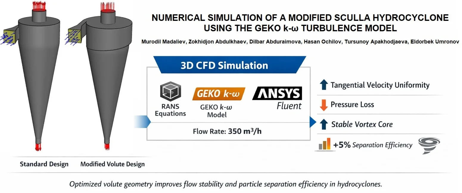
Abstract
This study presents a computational fluid dynamics (CFD) simulation of a modified hydrocyclone featuring a redesigned volute (inlet) geometry aimed at enhancing separation efficiency. The numerical investigation was conducted using the Reynolds-Averaged Navier-Stokes (RANS) equations with the - GEKO turbulence model under steady-state conditions. The modification primarily improved the tangential velocity distribution and reduced pressure losses in the separation zone. Compared to the standard configuration, the modified design achieved approximately 5 % higher particle separation efficiency and more uniform pressure contours. The study also provides a detailed analysis of flow fields and vortex structures to explain the mechanism behind performance enhancement. The findings demonstrate that the proposed volute modification can substantially improve flow stability and solid-liquid separation, offering a cost-effective design improvement for industrial hydrocyclones.
Highlights
- A modified Sculla hydrocyclone with an optimized volute inlet is numerically investigated using the GEKO k–ω turbulence model within a 3D RANS CFD framework.
- The redesigned volute inlet improves tangential velocity uniformity and stabilizes the vortex core, leading to reduced turbulence dissipation and pressure loss.
- CFD simulations reveal an average 5% increase in particle separation efficiency at a constant operating flow rate of 350 m³/h compared to the standard design.
- The GEKO k–ω turbulence model demonstrates strong capability in capturing anisotropic swirling flows typical of hydrocyclone separation processes.
1. Introduction
Hydrocyclones are widely used in various industries for the separation of solid-liquid mixtures and suspensions containing particles of different densities. Their operation is based on the centrifugal forces generated by the rotational flow inside the device, which facilitate efficient separation of components with varying densities. The key advantages of hydrocyclones include their simple design, compactness, absence of moving parts, and high operational reliability under extreme conditions of pressure and temperature.
In industrial applications, hydrocyclones are employed across multiple sectors. In the mining industry, they are used for mineral classification, desliming, and recovery of fine particles [1].
In the petrochemical sector, they serve to remove sand and solid impurities from drilling fluids and oil streams [2]. In the chemical and pharmaceutical industries, they are used for separation of catalysts and other particulate suspensions [3]. In the food industry, hydrocyclones enable separation of pulp, starch, and fibers from juice, dairy, and wort-based products, while in environmental and water treatment systems, they are applied for purification and recycling processes [4].
Recent studies have increasingly focused on the numerical simulation of hydrocyclone performance to understand the internal flow structure and improve separation efficiency. In works by [5] performed comparative studies using different turbulence models and demonstrated the strong dependence of separation efficiency on inlet velocity profiles. In [6] applied multiphase RANS modeling and highlighted the importance of turbulent dispersion and particle size distribution on the cut-size behavior. In works by [7] further developed the Generalized - (GEKO) model for enhanced accuracy in rotating flows and demonstrated its applicability for swirling flow simulations in jet-based configurations.
In [8], CFD modeling of hydrocyclone hydrodynamics was performed, demonstrating that accurate reproduction of swirl intensity and boundary layer interaction significantly impacts the prediction of energy losses and pressure drops. In [9], a comparative analysis of single and group centrifugal cyclones was conducted, enabling an assessment of the influence of flow interaction on separation efficiency. A subsequent study [10] examined the influence of slip on the formation of flow separation zones in a channel, allowing for a more accurate understanding of the development of turbulence in complex geometries. A study [11] focused on the numerical analysis of multiphase flows in a channel, demonstrating the potential of the CFD approach for describing phase interactions. In [12], a new two-fluid turbulence model for axisymmetric jets was proposed, providing a more accurate description of the dynamics of vortex structures. Finally, in [13], mathematical modeling of turbulent flow in a centrifugal separator was performed, demonstrating the effectiveness of using improved turbulence models for rotational flows.
From this review, it is evident that despite significant progress in CFD-based hydrocyclone analysis, limited attention has been paid to optimizing the volute (inlet) geometry, which plays a critical role in forming the rotational flow and determining separation performance. Standard hydrocyclone designs often generate non-uniform tangential velocity distributions and unstable vortex cores, leading to increased turbulence dissipation and reduced efficiency.
As summarized in Table 1, previous studies have primarily focused on improving turbulence models and predicting flow behavior in standard hydrocyclones. However, limited work has been done on analyzing the impact of modified inlet (volute) geometries on flow stability and separation efficiency using the GEKO - turbulence model. The present study addresses this gap by performing a comprehensive 3D CFD analysis with a modified inlet design and by comparing its hydrodynamic and separation characteristics to the standard configuration.
Table 1Summary of relevant studies on CFD modeling of hydrocyclones
No. | Reference | Method / model | Main findings | Limitations / remarks |
1 | Vakamalla and Mangadoddy (2017) | RANS with SST - model | Evaluated turbulence modeling effects on industrial hydrocyclones; SST model captured swirl better than - | Limited to standard geometry; no inlet modification |
2 | Azimian and Bart (2016) | CFD + erosion model | Predicted hydroabrasion effects; identified regions of high wall wear | Did not consider multiphase interaction |
3 | Delgadillo and Rajamani (2005) | RANS + turbulence comparison | Compared -, RSM, and SST models; RSM provided highest accuracy for swirling flows | Computationally expensive |
4 | Brennan et al. (2007) | Multiphase model + cut-size prediction | Modeled particle classification; validated cut-size correlations with experiments | Simplified boundary conditions |
5 | Durango-Cogollo et al. (2020) | CFD of hydrocyclone efficiency | Showed flow field strongly depends on inlet velocity distribution | Did not modify inlet geometry |
6 | Li et al. (2022) | GEKO - turbulence model | Demonstrated adaptive GEKO parameters improve prediction of heat transfer and swirling flow | No application to multiphase hydrocyclones |
7 | Madaliev et al. (2024) | Two-fluid turbulence model | Modeled multiphase flow in hydrocyclone groups; validated with experimental data | Group interaction only; no single modified geometry analysis |
In this context, the present study focuses on the numerical simulation of a modified hydrocyclone with an improved volute geometry using the GEKO - turbulence model implemented in ANSYS Fluent. The GEKO model offers enhanced adaptability compared to classical SST and - formulations, allowing more accurate representation of complex swirling flow fields typical of hydrocyclones. The main goal is to analyze the hydrodynamics, pressure and velocity distributions, and particle trajectories in both standard and modified designs, providing a comprehensive comparison of their performance under identical flow conditions.
The results of this study contribute to the development of more energy-efficient, high-performance hydrocyclones suitable for industrial applications involving intense turbulence, such as in mineral processing, water treatment, and fluid recirculation systems.
Previous related studies on hydrocyclone flow modeling reveal the following research gaps:
Most works applied - or SST - turbulence models, which are limited in capturing anisotropic swirling flows. The impact of volute (inlet) geometry on pressure losses and vortex stability has been insufficiently explored. Few studies performed quantitative validation using grid independence or convergence criteria. The coupling between flow hydrodynamics and particle trajectory prediction remains inadequately addressed. The GEKO - model, despite its flexibility, has not been applied to modified hydrocyclone designs.
During the study, all calculations are carried out at the same flow rate – 350 m3/h, which provides an objective basis for comparing the efficiency of various hydrocyclone designs. During the modeling process, the main attention is paid to the analysis of the distribution of velocities, pressure, and trajectories of solid particles, since these characteristics have the greatest impact on the operating indicators of the device. Thus, the results of this work contribute to the development of more efficient and energy-saving equipment capable of operating in complex hydrodynamic conditions.
In hydrocyclones, the separation efficiency is largely governed by the formation and stability of the swirling flow field inside the conical body. However, in conventional designs, the tangential velocity distribution near the inlet region is often non-uniform, leading to unstable vortex cores, higher turbulence dissipation, and reduced separation performance. To address this physical limitation, the present study proposes a modified volute (inlet) geometry that promotes a more uniform swirl intensity and smoother pressure gradient development. This modification aims to enhance the centrifugal force distribution, thereby improving particle separation efficiency and reducing pressure losses compared to the standard hydrocyclone configuration.
A review of previous research shows that significant progress has been achieved in understanding hydrocyclone hydrodynamics using CFD-based RANS approaches. The merits of earlier works include detailed modeling of turbulence, velocity fields, and separation behavior in conventional designs, often employing -, RSM, and SST - turbulence closures. However, the demerits lie in their limited attention to geometric optimization and the inability of standard models to accurately capture highly anisotropic swirling flows. Few studies have explored the influence of modified inlet (volute-type) geometries on the internal flow field and overall separation efficiency.
The novelty of the present research lies in combining an optimized volute-type inlet with the GEKO - turbulence model, which introduces tunable calibration parameters for better adaptation to strong swirling and recirculating flows. This integrated approach enables a more realistic prediction of pressure and velocity distributions, offering deeper insight into how geometric modifications enhance the hydrodynamic performance of hydrocyclones.
2. Mathematical and physical formulation of the problem
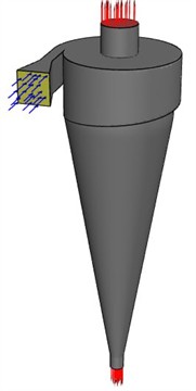
In this study, a full three-dimensional (3D) computational model of the hydrocyclone was used. Although the general geometry of a hydrocyclone appears axisymmetric, the internal flow is strongly three-dimensional due to the tangential inlet, the formation of double vortex cores, and the presence of secondary recirculation zones near the wall and vortex finder. These asymmetric flow patterns cannot be accurately represented using a 2D axisymmetric approach. Therefore, the 3D model was selected to fully capture the spatial variation of tangential, axial, and radial velocity components, as well as the detailed structure of the turbulent swirl flow. The model includes the volute-type tangential inlet, vortex finder, cylindrical and conical sections, and the underflow orifice, ensuring realistic representation of the flow field. Similar 3D modeling approaches have been successfully applied in previous numerical studies of hydrocyclones, showing that full three-dimensional simulations provide more accurate predictions of pressure distribution and particle separation efficiency.
Fig. 1 shows two types of hydrocyclones, with their dimensions.
The modified volute section provides a smoother tangential flow entry and a more uniform velocity distribution inside the cyclone body. This geometric change improves the formation of a stable vortex core, reduces local turbulence, and enhances solid-liquid separation efficiency compared to the standard design.
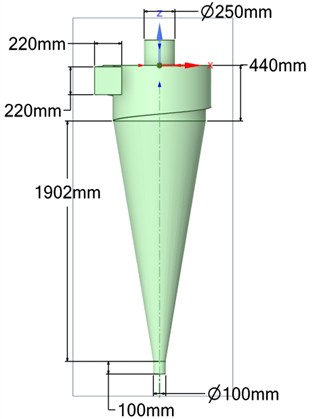
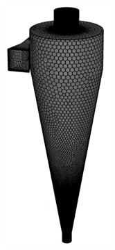
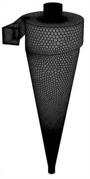
Fig. 2 shows schematic representations of hydrocyclones: (a) and (b) correspond to the standard design, while (c) and (d) represent the modified volute configuration, including their respective computational grids used for numerical modeling.
Fig. 1Two types of hydrocyclones with their main dimensions
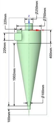
a) Standard design
b) With modified snail section
Fig. 2Schematic representation and computational grids of the a), b) standard and c), d) modified hydrocyclone models used in the numerical simulation
a)
b)
c)
d)
The modified inlet geometry Fig. 2(c-d) generates a more stable swirling flow and lower turbulence intensity near the inlet region. Mesh refinement was applied in high-gradient zones to accurately capture velocity and pressure variations critical for evaluating flow performance.
The computational domain was discretized using a polyhedral mesh generated in the ANSYS Fluent Meshing environment following the watertight geometry workflow. Local sizing was applied to critical regions such as the inlet, vortex finder, and underflow orifice to accurately capture steep gradients in velocity and pressure. The target mesh size was 5 mm with a growth rate of 1.2, and the boundary layer was resolved using three inflation layers with a transition ratio of 0.272 and a smooth-transition offset method. The resulting grid consisted of approximately 2.43 million cells, 1.62 million faces, and 3411 edges, as summarized in Fig. 2(c-d). A refinement strategy was implemented by applying a body of influence (BoI) around the inlet and cone regions to ensure accurate prediction of tangential velocity and swirl intensity. Polyhedral elements were chosen to minimize numerical diffusion and improve convergence stability in regions of high curvature and rotation. A grid independence study was performed using three mesh densities (1.2×10⁶, 2.4×10⁶, and 3.6×10⁶ cells). The variation in pressure drop and separation efficiency between the two finest grids was below 1.8 %, indicating that the medium-density grid (≈ 2.43×10⁶ cells) provides sufficient accuracy with reasonable computational cost. Therefore, this mesh was adopted for all subsequent CFD simulations.
To study the hydrodynamics of the flow in a modernized hydrocyclone with an improved spiral region, a system of equations was used to describe the behavior of a gas-liquid mixture containing solid particles. In the present study, the solid-liquid mixture is assumed to be dilute, meaning that the particle concentration is sufficiently low so as not to significantly affect the bulk properties of the carrier fluid. According to article [6], multiphase modeling of hydrocyclones demonstrated that, at low solid concentrations, particle-particle interactions can be neglected without substantial loss of accuracy in predicting the cut size. Similarly in article, [7] confirmed the suitability of the GEKO - model for accurately simulating turbulent and swirling flows under moderate particle loading, validating its capability to handle complex flow patterns. In addition in article [9] numerically analyzed centrifugal cyclone systems and also employed the dilute-phase assumption ( 0.01), showing that neglecting two-way coupling between the liquid and solid phases remains valid for this concentration range. Under these conditions, the continuous liquid phase governs the overall flow field, while the solid particles are treated as a dispersed phase influenced primarily by centrifugal, drag, and gravitational forces. Within the rotational motion of the hydrocyclone, these forces determine particle trajectories and the efficiency of separation.
The computational domain boundaries are shown in Fig. 2. Appropriate boundary conditions were applied to reproduce the real operating conditions of the hydrocyclone. At the inlet, a velocity inlet condition was specified, with a uniform velocity corresponding to a volumetric flow rate of 350 m3/h, and a turbulence intensity of 5 % with a turbulence viscosity ratio of 10. The outlet at the overflow was defined as a pressure outlet with a gauge pressure of 0 Pa, allowing free discharge of the liquid core flow. The underflow orifice was modeled as a pressure outlet with the same pressure condition to enable symmetric flow separation between overflow and underflow.
All solid surfaces of the hydrocyclone body were treated as no-slip walls, with standard wall functions applied for near-wall turbulence modeling. The vortex finder and underflow spigot were included in the domain geometry, ensuring realistic pressure and velocity distributions near the outlet zones. The axis of symmetry was defined along the cyclone’s central axis to ensure flow symmetry and computational stability.
These boundary conditions are consistent with experimental and numerical studies of hydrocyclones [6], and have been shown to accurately reproduce the characteristic Rankine-type vortex and air core formation typical of high-Reynolds-number swirling flows.
Their interaction determines the trajectories of particle motion and the efficiency of the separation process. For numerical modeling of this problem, the Reynolds-averaged Navier-Stokes system of equations (RANS approach) is used. The - GEKO model was chosen as a turbulence model, which allows for a wide range of turbulent regimes and is adapted to local flow conditions, which is especially important for vortex and highly turbulent flows in a hydrocyclone. Thus, to adequately describe the movement and transport of solid particles in modified cyclonic devices, it is sufficient to take into account the effect of centrifugal force, environmental resistance and gravity within the framework of the selected turbulent model:
The SST GEKO (Generalized -) turbulence model developed by Ansys is an improved version of the classical SST (Shear Stress Transport) model with extended calibration capabilities. Its main advantage lies in the increased accuracy and flexibility when modeling complex turbulent flows, especially those involving strong rotation, flow separation, or large velocity gradients. Such characteristics make it highly suitable for analyzing complex systems like hydrocyclones and centrifuges, where detailed turbulence representation is crucial. According to article [7], the GEKO model demonstrates enhanced adaptability for a wide range of turbulent regimes and provides more accurate prediction of anisotropic swirling flows and heat transfer characteristics. Similarly, in article [8] successfully applied CFD modeling to investigate the hydrodynamics of hydrocyclones, confirming that proper turbulence modeling is essential for capturing energy losses and pressure gradients in rotational flows. In addition [9] conducted numerical analyses of centrifugal cyclone systems and validated the capability of the GEKO-based approach to reproduce realistic tangential velocity distributions and pressure profiles in strongly swirling flows. These findings collectively justify the choice of the GEKO k–ω turbulence model in the present study, as it offers superior performance for capturing the complex hydrodynamics of the modified hydrocyclone configuration.
The model is based on the transport equations for turbulent kinetic energy () and specific dissipation rate (), expressed as:
where, is the turbulence production term, , , , , are empirical model constants calibrated for enhanced generality.
The transport equations for turbulent kinetic energy and specific dissipation rate, given in Eq. (2), follow the GEKO - model formulation described by [7], where additional calibration parameters enhance adaptability to different turbulent regimes.
Turbulent eddy viscosity is calculated by: :
In Eqs. (3-7), the following parameters and coefficients are used: – turbulent (eddy) stress tensor, 1.2 –model correction coefficient for corner flows, – cross-diffusion term coefficient. The GEKO model introduces additional calibration functions (, , ) and adjustable coefficients (, ) that provide flexibility for different flow regimes, including swirling and separated flows. The blending function automatically distinguishes between near-wall and free-shear regions in the computational domain: 1 for near-wall flows and 0 for free-shear regions. In near-wall zones ( 1), the coefficients and are activated to improve boundary-layer prediction, whereas in free-shear regions ( 0), the coefficients and control mixing and jet spreading. The specific functional forms of and the free coefficients (, , ) are proprietary and not yet publicly available in the open literature. The model constants were adopted as follows: 0.09, 2.0, 2.0, 0.52, and the blending function 1 in the near-wall region.
Particle tracking. When modeling the operation of a hydrocyclone, it is necessary to take into account a number of key equations. One of them describes the kinematics of particle motion, and the other describes their interaction with the surrounding liquid medium. As noted in [14], the particles in the flow inside the hydrocyclone are mainly affected by the following forces: the resistance force of the medium, pressure (pressure gradient), and the lifting force, known as the Saffman force. The Saffman lift force was included in the particle motion model to account for the lateral force acting on small particles moving in shear flows. This force becomes significant when the particle Reynolds number () is below approximately 100 and the local shear rate is high, as typically observed in the near-wall regions of hydrocyclones. Under these conditions, the lift force can influence particle trajectories and separation behavior. In this study, the mean particle diameters ranged from 20 µm to 80 µm, corresponding to values between 5 and 60, which falls within the valid range for applying the Saffman formulation [15]. For larger or highly turbulent particles (100), the contribution of lift is generally negligible compared to drag and centrifugal forces; hence, its effect was limited to the low-inertia particle population. The inclusion of this term improves accuracy in predicting fine particle separation without significantly increasing computational cost.
In this model, the primary forces acting on solid particles – centrifugal, drag, and gravity – were taken into account, as they dominate the motion of small spherical particles in hydrocyclone flows. According to in article [15], centrifugal and drag forces are the primary factors determining particle trajectories within hydrocyclones, while the influence of secondary effects such as buoyancy or pressure gradient imbalance remains minimal for small particle sizes. Furthermore, article [16] demonstrated in their numerical study of three-phase (liquid-gas-solid) flows in hydrocyclones that neglecting the Basset force and Magnus lift forces does not lead to noticeable errors in the prediction of particle motion when the particle diameter is less than 100 μm and the particle Reynolds number () is less than 50. Therefore, in this work, these secondary forces were omitted in accordance with established practice in CFD modeling of dilute multiphase hydrocyclone systems, since this simplification does not significantly affect the accuracy of the predicted particle trajectories. Taking these considerations into account, the particle motion can be expressed by Eq. (8).
Eq. (8) represents the balance of forces acting on a particle within the rotating flow field and follows the classical formulation described by article [15], where centrifugal, drag, and gravitational forces govern the particle motion inside a hydrocyclone:
where – resistance per unit mass of the particle. This force is balanced by the action of the centrifugal force. Since the particles are considered smooth and have the shape of small spheres, the expression for can be represented as follows:
where the Reynolds number is:
In this study, the continuous liquid phase was solved under steady-state (stationary) conditions using the RANS equations with the GEKO - turbulence model. This approach was adopted because, under the operating flow rate of 350 m3/h, the hydrodynamic field inside the hydrocyclone reaches a statistically stable pattern characterized by a quasi-steady vortex structure. Solving the steady flow field significantly reduces computational cost while preserving the accuracy of mean velocity and pressure distributions. Once the steady flow solution was obtained, the particle motion was computed in a transient (unsteady) manner using a Lagrangian discrete phase model (DPM). This transient tracking allowed capturing the time-dependent trajectories and residence times of particles as they moved through the swirling flow. The combined steady – transient approach is widely used in hydrocyclone simulations [6], as it provides a good balance between physical realism and computational efficiency.
The particle trajectories were computed using a Lagrangian particle tracking approach implemented in ANSYS Fluent. The equations of motion were solved by integrating the particle velocity and position in time using a second-order implicit Runge-Kutta scheme, which ensures numerical stability for high-gradient flows in the hydrocyclone. The time step was set to 1×10⁻⁴ s after a sensitivity analysis confirming that smaller steps did not significantly affect the results. Step-size control was automatically adjusted based on the local Courant number to maintain stable integration across regions of strong velocity gradients. The coupling between the continuous (liquid) and discrete (solid) phases was treated using a one-way coupling assumption, meaning that the fluid flow field influences the particle motion, but the particle loading is sufficiently low ( 1%) to neglect the feedback of particles on the fluid phase. This assumption is widely used for dilute particle-laden flows in hydrocyclones [6]. Each particle trajectory was computed until it either exited through the underflow or overflow boundary, at which point the particle’s residence time and terminal velocity were recorded for efficiency analysis. This procedure allows a statistically converged prediction of particle capture efficiency while maintaining computational accuracy.
3. Calculation results and their discussion
The developed mathematical and numerical model provides a comprehensive representation of the hydrodynamic and particle motion characteristics inside the hydrocyclone. By resolving the three-dimensional velocity, pressure, and turbulence fields, the model captures the key flow features – such as vortex core formation, tangential velocity gradients, and axial recirculation zones – that govern particle separation performance. The validated steady-state flow field obtained from the GEKO - RANS formulation serves as the foundation for the subsequent transient particle tracking simulations. This integrated modeling framework enables detailed analysis of how modifications in the inlet geometry influence flow stability, pressure drop, and separation efficiency, which are discussed in the following section.
Fig. 3 shows the isolines of the velocity distribution in the longitudinal section of the central zone of the hydrocyclone.
Fig. 3 clearly illustrates the differences in the flow velocity distribution between the standard and the modified hydrocyclone configurations. In the standard design (left), the velocity field shows a strong non-uniformity near the inlet and the upper cylindrical section, where zones of high velocity (above 8.5 m/s) are concentrated asymmetrically. This leads to an unstable vortex core and higher turbulence intensity. In contrast, the modified volute (snail) section (right) produces a smoother and more uniform velocity profile along the central axis, with a gradual decrease in velocity from the wall toward the axis. The improved distribution indicates enhanced swirl uniformity and reduced local turbulence dissipation, which contributes to a more stable vortex structure and higher separation efficiency of the hydrocyclone. These observations confirm that the redesigned inlet geometry effectively improves the hydrodynamic stability and energy efficiency of the device, in agreement with previously reported CFD findings [16].
Fig. 3Velocity field isolines
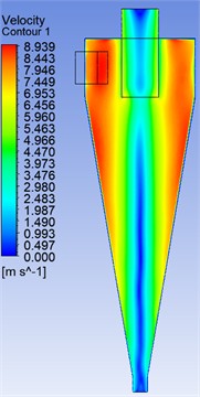
a) Standard design
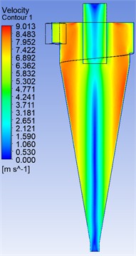
b) With modified snail section
Fig. 4 shows the region of maximum flow velocities, the so-called velocity core, which forms inside the hydrocyclone. This zone is important for the phase separation process, since it is where the action of centrifugal forces, which determine the behavior of particles, their trajectories, and the degree of separation, is most active.
Fig. 4Velocity core region
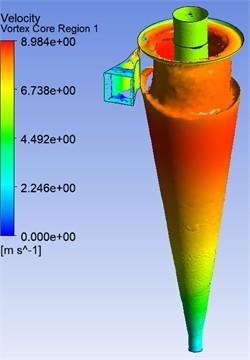
a) Standard design
b) With modified snail section
Fig. 4 compares the three-dimensional velocity core regions in the standard and modified hydrocyclone configurations. In the standard design (left), the vortex core appears elongated and unstable, extending irregularly toward the underflow region. The flow shows significant asymmetry, with zones of high velocity (above 6.7 m/s) concentrated near the wall, indicating increased turbulence and energy loss. In contrast, the modified volute (snail) section (right) produces a more compact and symmetric vortex core with a well-defined central axis. The velocity distribution is smoother, and the high-velocity region is confined to the upper cylindrical part, suggesting improved flow organization and reduced secondary recirculation. These results indicate that the redesigned inlet geometry enhances the formation and stability of the vortex core, minimizes energy dissipation, and contributes to improved particle separation efficiency within the hydrocyclone.
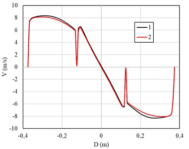
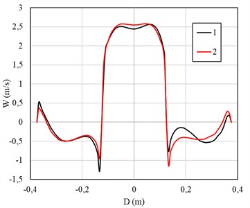
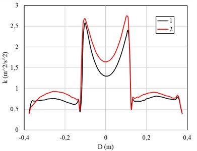
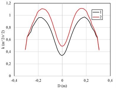
Fig. 5 shows a section of the central part of the hydrocyclone at a depth of 400 mm from the cover of the device, where the distributions of tangential, longitudinal velocity, as well as the kinetic energy of turbulence are compared. This section allows us to evaluate the contribution of various flow components, such as the main and turbulent kinetic energy, and their influence on the overall dynamics of the flow in the hydrocyclone.
Fig. 5Comparison of the distribution of a) tangential, b) longitudinal velocity and c) kinetic energy of turbulence
а)
b)
с)
Fig. 5 presents the velocity and turbulence characteristics in the central section of the hydrocyclone at a depth of 400 mm. The graphs compare the results for the standard design (curve 1) and the modified volute (snail) section (curve 2). In the tangential velocity distribution (Fig. 5(a)), the modified design shows a smoother velocity gradient near the wall and a more symmetric profile around the central axis. The reduction in local peaks indicates improved swirl uniformity and lower turbulence anisotropy compared to the standard configuration. The longitudinal velocity profile (Fig. 5(b)) demonstrates that the modified hydrocyclone achieves more stable axial flow with reduced recirculation zones, which helps maintain a steady vortex core and minimizes backflow near the centerline. In the turbulent kinetic energy distribution (Fig. 5(c)), the modified configuration exhibits slightly higher energy near the wall region but lower fluctuations in the core, suggesting a better balance between turbulence production and dissipation.
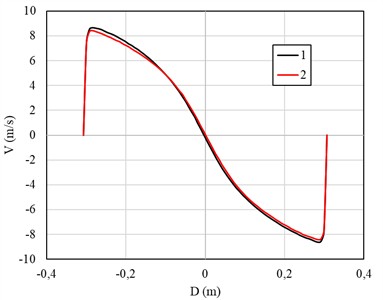
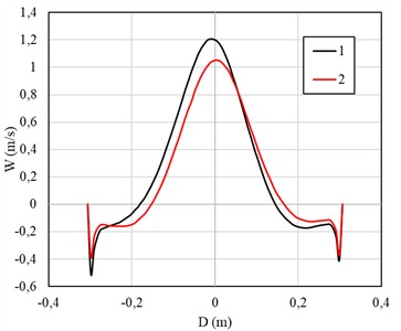
Fig. 6 shows a section of the central part of the hydrocyclone at a depth of 800 mm from the cover of the device, where the distributions of tangential, longitudinal velocity, as well as the kinetic energy of turbulence are compared. This section allows a more detailed analysis of the changes in the flow characteristics at a greater depth of the device and their impact on the separation efficiency and flow dynamics in the hydrocyclone.
Fig. 6Comparison of the distribution of a) tangential, b) longitudinal velocity and c) kinetic energy of turbulence
а)
b)
с)
Fig. 6 comparison of distributions of: a) tangential velocity, b) longitudinal velocity and c) turbulent kinetic energy for the standard (1) and modified (2) hydrocyclones. The graphs show that the modified hydrocyclone flow exhibits changes in the distribution of velocities and turbulent energy, indicating possible improvements in flow dynamics and separation efficiency. Fig. 6. Comparison of distributions of: a) tangential velocity, b) longitudinal velocity and c) turbulent kinetic energy at a depth of 800 mm from the cover for the standard (1) and modified (2) hydrocyclones.
The results demonstrate a change in the flow pattern at greater depths, where the modified volute design affects the velocity distribution and the level of turbulent kinetic energy, which potentially contributes to an increase in the efficiency of phase separation. To evaluate the performance of the hydrocyclone, Fig. 7 presents the values of the percentage capture of particles with densities 2500, 3500 and 4500 kg/m3. The graph illustrates what proportion of particles of different sizes can be effectively separated depending on the flow parameters and the device configuration. These results allow conclusions to be drawn about the degree of separation efficiency and serve as a basis for optimizing the performance of the hydrocyclone.
Fig. 7 illustrates the particle capture efficiency curves for the standard and modified hydrocyclone designs at three particle densities. For particles with 2500 kg/m3, the modified hydrocyclone (curve 2) shows a noticeable increase in capture efficiency across the full size range, particularly for medium-sized particles ( 20-35 μm), where the efficiency rises from approximately 57 % to 64 %. At 3500 kg/m3, both designs achieve higher overall efficiency, but the modified configuration demonstrates a more rapid transition to full particle capture (100 %) at smaller particle diameters, indicating improved separation sharpness. For 4500 kg/m3, the difference between the two designs becomes smaller since the higher particle density enhances centrifugal separation in both cases; however, the modified design still maintains slightly higher efficiency and smoother performance trends. Overall, the modified spiral (snail) section achieves an average 5 % increase in particle capture efficiency compared to the standard design at the same flow rate. This improvement confirms that the optimized inlet geometry promotes a more uniform tangential velocity distribution, enhancing the separation process and reducing particle losses through the overflow.
Fig. 7Percentage of particle capture
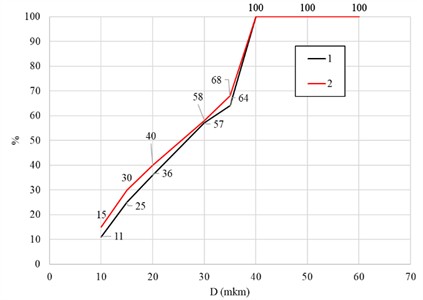
a) 2500 kg/m3
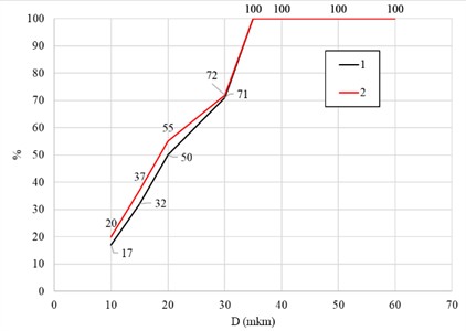
b) 3500 kg/m3
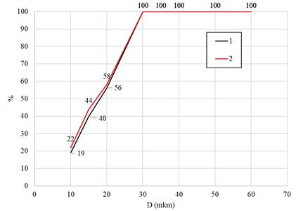
c) 4500 kg/m3
4. Conclusions
The conducted studies revealed significant differences in the flow characteristics between the standard and modified (with a volute) hydrocyclones. Particularly noticeable are the differences in the distribution of tangential and longitudinal velocities, as well as turbulent kinetic energy, where the modified design demonstrates higher efficiency. The modified hydrocyclone exhibits more stable velocity profiles in the central part of the flow and increased values of turbulent kinetic energy, which contributes to a more efficient phase separation process. The results obtained at different depths ( 400 mm and 800 mm) made it possible to analyze the flow development along the axis and evaluate the effect of design changes on the hydrodynamic state inside the device. In general, the proposed modification with a volute contributes to an increase in the efficiency of the hydrocyclone and can be recommended for further implementation in industrial technologies. Future works will focus on extending the current CFD model to include two-way coupling between the liquid and solid phases to better represent dense suspensions and particle – particle interactions. Additionally, the model will be expanded to study different inlet geometries and cone angles to identify optimal configurations that minimize pressure drop while maximizing separation efficiency. Future research will also involve experimental validation of the simulated velocity and pressure fields to confirm the numerical findings and ensure the reliability of the proposed design for industrial-scale applications.
References
-
T. R. Vakamalla and N. Mangadoddy, “Numerical simulation of industrial hydrocyclones performance: Role of turbulence modelling,” Separation and Purification Technology, Vol. 176, pp. 23–39, Apr. 2017, https://doi.org/10.1016/j.seppur.2016.11.049
-
M. Azimian and H.-J. Bart, “Numerical analysis of hydroabrasion in a hydrocyclone,” Petroleum Science, Vol. 13, No. 2, pp. 304–319, Apr. 2016, https://doi.org/10.1007/s12182-016-0084-7
-
M. Karimi, G. Akdogan, S. M. Bradshaw, and A. Mainza, “Numerical modelling of air core in hydrocyclones,” in Proceedings of the Ninth International Conference on CFD in the Minerals and Process Industries, Dec. 2012.
-
K. T. Hsieh and K. Rajamani, “Phenomenological model of the hydrocyclone: Model development and verification for single-phase flow,” International Journal of Mineral Processing, Vol. 22, No. 1-4, pp. 223–237, Apr. 1988, https://doi.org/10.1016/0301-7516(88)90065-8
-
J. A. Delgadillo and R. K. Rajamani, “A comparative study of three turbulence-closure models for the hydrocyclone problem,” International Journal of Mineral Processing, Vol. 77, No. 4, pp. 217–230, Dec. 2005, https://doi.org/10.1016/j.minpro.2005.06.007
-
M. S. Brennan, M. Narasimha, and P. N. Holtham, “Multiphase modelling of hydrocyclones – prediction of cut-size,” Minerals Engineering, Vol. 20, No. 4, pp. 395–406, Apr. 2007, https://doi.org/10.1016/j.mineng.2006.10.010
-
Z. Li, Y. Liu, W. Zhou, X. Wen, and Y. Liu, “Thermal pollution level reduction by sweeping jet-based enhanced heat dissipation: A numerical study with calibrated Generalized k-ω (GEKO) model,” Applied Thermal Engineering, Vol. 204, p. 117990, Mar. 2022, https://doi.org/10.1016/j.applthermaleng.2021.117990
-
M. Durango-Cogollo, J. Garcia-Bravo, B. Newell, and A. Gonzalez-Mancera, “CFD modeling of hydrocyclones-a study of efficiency of hydrodynamic reservoirs,” Fluids, Vol. 5, No. 3, p. 118, Jul. 2020, https://doi.org/10.3390/fluids5030118
-
M. Madaliev et al., “Numerical analysis of single SC-50-800 and SC-50-500x2-x4 group centrifugal cyclones: efficiency comparison,” in E3S Web of Conferences, Vol. 508, p. 06005, Apr. 2024, https://doi.org/10.1051/e3sconf/202450806005
-
M. Madaliev et al., “The effect of slip on the development of flow separation due to a bump in a channel based on a two-fluid turbulence model,” in E3S Web of Conferences, Vol. 508, p. 06003, Apr. 2024, https://doi.org/10.1051/e3sconf/202450806003
-
M. Madaliev, Z. Abdulkhaev, K. Kurpayanidi, A. Abdullayev, and A. Ilyosov, “Study of the SST turbulence model for the 2D NASA wall-mounted hump separated FLOW problem with plenum case,” in E3S Web of Conferences, Vol. 508, p. 06007, Apr. 2024, https://doi.org/10.1051/e3sconf/202450806007
-
Z. M. Malikov, M. E. Madaliev, D. P. Navruzov, and K. Adilov, “Numerical study of an axisymmetric jet based on a new two-fluid turbulence model,” in International Conference on Actual Problems of Applied Mechanics – APAM-2021, Vol. 2637, No. 1, p. 040023, Jan. 2022, https://doi.org/10.1063/5.0118473
-
Z. M. Malikov and M. E. Madaliev, “Mathematical modeling of a turbulent flow in a centrifugal separator,” (in Rusian), Vestnik Tomskogo gosudarstvennogo universiteta. Matematika i mekhanika, No. 71, pp. 121–138, Jan. 2021.
-
P. Rudolf, “Simulation of multiphase flow in hydrocyclone,” in EPJ Web of Conferences, Vol. 45, p. 01101, Apr. 2013, https://doi.org/10.1051/epjconf/20134501101
-
Y. Zhang, P. Cai, F. Jiang, K. Dong, Y. Jiang, and B. Wang, “Understanding the separation of particles in a hydrocyclone by force analysis,” Powder Technology, Vol. 322, pp. 471–489, Dec. 2017, https://doi.org/10.1016/j.powtec.2017.09.031
-
M. Murodil, A. Zokhidjon, A. Aybek, M. Khamidulla, and G. Mushtariybonu, “Numerical Study of Three-Phase Liquid-Gas-Solid Flow in Single and Group Hydrocyclones,” Journal of Mechanical Engineering, Vol. 75, No. 1, pp. 103–110, Apr. 2025, https://doi.org/10.2478/scjme-2025-0011
About this article

The authors have not disclosed any funding.
The datasets generated during and/or analyzed during the current study are available from the corresponding author on reasonable request.
Murodil Madaliev: conceptualization, methodology, numerical simulation, manuscript writing, and overall supervision of the research, proofreading, and preparation of the final version of the manuscript. Zokhidjon Abdulkhayev: data processing, and analysis of simulation results. Dilbar Abduraimova: preparation of literature review, editing, and formatting of the manuscript. Hasan Ochilov: visualization of results, preparation of figures, and verification of simulation data. Tursunoy Apakhodjaeva: assistance in numerical computation and statistical analysis. Eldorbek Umronov: validation of the CFD model.
The authors declare that they have no conflict of interest.
