Abstract
The structural reliability of locomotive frames is essential for ensuring the safety and durability of railway operations. This study presents a full-scale experimental assessment of the residual deflection and stiffness of the UzTE16M locomotive frame under static loading, supported by finite element method (FEM) validation. Tests were performed on three locomotives (Nos. 005, 010, and 019) at “O‘ztemiryo‘lmashta’mir” JSC under loads of 15, 30, and 40 tons, with deflections measured at three control points. The load–deflection response was nearly linear up to 30 tons, confirming elastic behavior, while at 40 tons a slight deviation appeared, with a maximum deflection of 11.2 mm. Residual deflections of 2-6 mm remained within regulatory limits. FEM analysis reproduced identical boundary conditions, showing a maximum von Mises stress of 127 MPa – below the 235 MPa yield strength – and a deviation of less than 5 % from test results. The integrated experimental-numerical approach effectively evaluates stiffness degradation and residual deflection, offering a reliable framework for fatigue diagnostics, condition-based maintenance, and extending the service life of modernized locomotive frames.
Highlights
- Static loading tests of UzTE16M locomotive frames showed nearly linear deflection behavior up to 30 tons, confirming elastic structural response.
- A 40-ton load caused measurable nonlinear deformation and stiffness reduction, indicating the onset of semi-plastic behavior in the frame.
- Residual deflections after unloading were within 2–6 mm, meeting regulatory limits and confirming no critical permanent deformation.
- FEM analysis reproduced test conditions with <5% deviation, validating the accuracy and reliability of the computational model.
- The integrated experimental–numerical approach provides a robust framework for condition-based maintenance and service-life estimation.
1. Introduction
The structural integrity of locomotive frames plays a decisive role in ensuring the safety, durability, and operational reliability of railway rolling stock. During long-term service, locomotives are subjected to complex static-dynamic loads, leading to fatigue phenomena, elastic and plastic deformations, and cyclic stresses that cause material degradation. The resulting residual deflections and gradual reduction of structural stiffness are key indicators for assessing the degree of structural ageing.
Between 2009 and 2013, a large-scale modernization program was implemented at “O‘zbekiston temir yo‘llari” JSC. Within this program, Soviet-era TE10M diesel locomotives were upgraded to the UzTE16M type. The modernization improved power supply, control equipment, and diesel-generator units; however, the welded steel frame – the primary load-bearing element – remained unchanged. As the frame determines both the residual service life and operational safety of the locomotive, evaluating its current mechanical condition is an important engineering and scientific task.
Previous research on railway vehicle structures has mainly relied on finite element method (FEM) simulations to study fatigue and stress-strain behavior. In [1], the nonlinear bending of locomotive frames was investigated, showing that structural stiffness is highly sensitive to load variation and confirming the importance of static testing for fatigue prediction. In [2], FEM was applied to metro car bodies, and the correlation between stress concentration zones and experimental bending data was established, validating the complementarity of numerical and experimental methods. In [3], the approach was extended by comparing FEM-based static and modal analyses with measured data, proving the reliability of computational validation.
Despite these contributions, most prior studies have focused on new or uniformly loaded frames, while little attention has been given to modernized or aged locomotive structures operating under increased loads and prolonged service life. Such structures – including the UzTE16M locomotives – still retain welded steel frames from earlier generations, which are prone to residual stresses, fatigue damage, and local stiffness reduction.
Over the past decade, many researchers have examined the mechanical behavior, fatigue life, and reliability of railway vehicles using experimental testing and FEM simulations. In [4], an engineering approach for estimating the remaining life of welded locomotive frames was developed, proving that residual stiffness can serve as a diagnostic indicator for extending operational service. The study [5] simulated the stress-strain state of bogie frames and identified high-stress concentration zones that corresponded to experimental deformation points, validating FEM as an effective predictive tool.
In [6], fault analysis of diesel locomotives identified the most critical structural and operational failures, while [7, 8] analyzed the stress-strain behavior of industrial electric locomotive frames (PE2M and PE2U types), confirming that welding geometry and load distribution play decisive roles in stiffness degradation. The bending behavior of aged locomotive frames as an indicator of structural fatigue and residual strength is demonstrated in [9]. In [10], the service life of cast bogie parts was extended based on full-scale running tests, emphasizing the importance of experimental verification in predicting fatigue resistance. The paper [11] introduced a passenger wagon converted into a dynamometric test vehicle, enabling real-time measurement of loads and stresses under actual conditions. In [12], specialized instruments for studying wheel-rail adhesion were developed, improving traction efficiency assessment. The study [13] examined uncertain suspension parameters affecting dynamic responses of railway vehicles, showing their influence on vibration amplitude and stability. The study [14] combined analytical and experimental evaluations to assess the operating life of locomotive parts under prolonged cyclic loads.
Collectively, these works demonstrate the convergence between experimental diagnostics and FEM-based modeling in assessing fatigue life and structural integrity of railway components. However, the specific issue of stiffness degradation and residual deflection in modernized locomotive frames, such as the UzTE16M, remains insufficiently explored, defining the scientific novelty and relevance of the present research.
2. Methods
2.1. Object of research
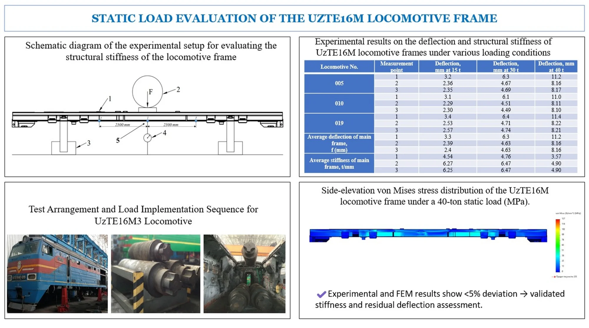
Experimental studies were conducted under enterprise conditions to evaluate the frame structure of the UzTE16M locomotive under static loads. As shown in Fig. 1, the locomotive frame was mounted on a base with four horizontal planes. The frame deflection was measured using a calibrated indicator with an accuracy of 0.01 mm. The measuring device was installed under the main longitudinal beam at the center of the locomotive frame, and the initial (zero) position was marked. In this setup, measurements of the locomotive frame structure were taken from point 1 at the center, and from points 2 and 3 located 2500 mm to the right and left of the center, respectively.
Subsequently, sequential loads of 15 t, 30 t and 40 t were applied to the central region of the frame. At each loading stage, deflection values were recorded. The loads were then gradually reduced (first to 10 t, then to 15 t), and the residual deflection values were also measured.
All load and deflection data were documented in a dedicated test log in real time. According to current technical regulations, no changes are permitted in the log after testing. If an error is detected in a record, the incorrect entry is crossed out with a single line, and the corrected value is written above, accompanied by the signature of the responsible tester and the date.
This methodology provides a reliable means of determining the deformation resistance and stiffness characteristics of the frame structure. In addition to evaluating the elastic and plastic deformation limits, it also allows the measurement of residual deflection, which serves as an indicator of structural fatigue.
Importantly, the methodology is generalizable and can be applied to locomotives with wagon-type bodies as well.
Fig. 1Schematic diagram of the experimental setup for evaluating the structural stiffness of the locomotive frame. 1 – locomotive frame; 2 – applied load; 3 – supporting base (pedestal); 4 – deflection measurement indicator; 5 – points for measuring the static deflection of the frame under applied loading
3. Procedure for conducting the experiment and collecting data
The experimental tests were carried out at “O‘ztemiryo‘lmashta’mir” JSC, the only facility in Central Asia specialized in locomotive overhauls and operating under “O‘zbekiston temir yo‘llari” JSC. This site was chosen because it is equipped with the necessary lifting, loading, and measuring devices required for conducting frame structure tests.
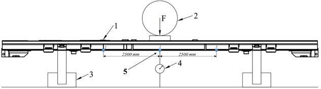
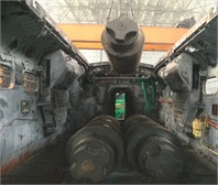
The research was performed on UzTE16M mainline locomotives, as illustrated in Fig. 2. Testing several units allowed the applied methodology to provide a more comprehensive assessment of the technical condition and deformation characteristics of the UzTE16M frame structures.
Fig. 2Test setup of UzTE16M3 series mainline locomotive No. 019
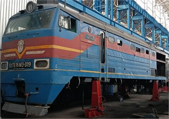
Fig. 2 shows the UzTE16M3 No. 019 locomotive, which is of the wagon-type design, with its frame structure positioned on four level supports. Figure 3 illustrates the testing process, where lifting cranes were used to apply the test loads and place them onto the locomotive frame. The deflections were measured at the center of the main longitudinal beam using a dial indicator with an accuracy of 0.01 mm.
Fig. 3 illustrates the test loads and their placement on the locomotive frame structure. During the experiment, the UzTE16M locomotive frame was subjected to stepwise application of static loads of different magnitudes. The tests were carried out in the range of 15 t, 30 t, and 40 t. These loads were installed at the central section of the frame using a crane, and at each stage the deflection was accurately measured with precision indicators.
In the subsequent phase of the test, the loads were gradually reduced, and the residual deflection of the frame under unloading was monitored. All deflection values were continuously documented in the official test log. This procedure was designed to simulate load levels close to real operating conditions of the locomotive and to provide an assessment of the technical state of the frame structure.
Fig. 3Implementation of the testing process: a) test loads of different weights; b) placement of the loads onto the locomotive frame using a crane
a)
b)
4. Data processing and analysis
All measurements obtained during the experimental tests were systematically documented in a dedicated test log and subjected to preliminary statistical processing. For each loading stage, the deflection readings taken from three points were averaged. In addition, variance and standard deviation were determined to evaluate the reliability of the measurements. The relative error of the results was required not to exceed ±2 %. The structural stiffness () was calculated from the relationship between the applied load and the corresponding deflection, expressed as follows Eq. (1):
where k denotes the structural stiffness (kN/mm), is the change in applied load (kN), represents the corresponding change in deflection (mm).
Residual deformation was determined from the deflection values recorded after the complete removal of the applied loads. This parameter reflects the combined contribution of elastic and plastic components within the frame. Through this approach, it was possible to identify the elastic limit, the onset of plastic deformation, and the progressive stages of fatigue development in the frame. The processed statistical results were represented in the form of load-deflection and load-residual deformation diagrams, allowing for the assessment of stiffness variation at each loading stage. Consequently, the elastic region, the nonlinear (semi-plastic) region, and the stage of plastic deformation were clearly distinguished.
5. Results and discussion
Using the methodology described above, Table 1 presents the results of static load measurements for the UzTE16M main frame structures of locomotives No. 005, No. 010, and No. 019. The data reflect the measured deflections and residual deformations under different loading stages, providing a comparative basis for assessing the stiffness characteristics of the tested frames. These results allow for a more precise evaluation of the elastic and plastic responses of the locomotive frames, as well as the identification of potential variations in structural behavior among different units.
The results of static loading tests were evaluated for three UzTE16M locomotive frames (Nos. 005, 010, and 019). Measurements were taken at three control points under loads of 15 t, 30 t, and 40 t. In all cases, deflection increased almost linearly with load. For instance, at point 1 of locomotive No. 005, the deflection was 3.2 mm at 15 t, 6.3 mm at 30 t, and 11.2 mm at 40 t. Similar results were observed for locomotives No. 010 and No. 019, confirming elastic behavior consistent with Hooke’s law.
Table 1Experimental results on the deflection and structural stiffness of UzTE16M locomotive frames under various loading conditions
Locomotive No. | Measurement point | Deflection, mm at 15 t | Deflection, mm at 30 t | Deflection, mm at 40 t |
005 | 1 | 3.2 | 6.3 | 11.2 |
2 | 2.36 | 4.67 | 8.16 | |
3 | 2.35 | 4.69 | 8.17 | |
010 | 1 | 3.1 | 6.1 | 11.0 |
2 | 2.29 | 4.51 | 8.11 | |
3 | 2.30 | 4.49 | 8.10 | |
019 | 1 | 3.4 | 6.4 | 11.4 |
2 | 2.53 | 4.71 | 8.22 | |
3 | 2.57 | 4.74 | 8.21 | |
Average deflection of main frame, (mm) | 1 | 3.3 | 6.3 | 11.2 |
2 | 2.39 | 4.63 | 8.16 | |
3 | 2.4 | 4.63 | 8.16 | |
Average stiffness of main frame, t/mm | 1 | 4.54 | 4.76 | 3.57 |
2 | 6.27 | 6.47 | 4.90 | |
3 | 6.25 | 6.47 | 4.90 |
A comparative analysis showed that locomotives No. 005 and No. 010 had nearly identical stiffness, while No. 019 displayed slightly higher deflections (up to 11.4 mm at 40 t), indicating reduced stiffness and a potential tendency toward higher deformation during service. The mean deflections across all control points were 2.9 mm at 15 t, 4.6 mm at 30 t, and 8.2 mm at 40 t, demonstrating a linear load-deflection relationship and sufficient strength margin.
Calculated stiffness values ranged from 6.25-6.47 t/mm, indicating uniform load distribution. However, slightly lower stiffness at the central point (6.25 t/mm) suggests a potential stress concentration zone. Overall, the UzTE16M frames demonstrated adequate stiffness for operational use, although the higher deflection of frame No. 019 indicates the need for structural monitoring or reinforcement.
Comparison with the Rules for the Plant Repair of TE10M and TE3 Diesel Locomotives showed that the maximum measured deflection of 11.2 mm under 40 t remained within the 15 mm regulatory limit. Although a minor stiffness decrease was recorded, total deformation did not exceed the permissible range. Residual deflections of 2-6 mm also met tolerance standards for flatness and perpendicularity, implying that reinforcement would be required only under higher loading conditions.
The experimental findings confirm that the UzTE16M frame maintains structural stability under static loading. The load-deflection curve remained nearly linear up to 30 t (elastic stage), with a slight deviation at 40 t, where stiffness decreased to 3.57 t/mm. Residual deformations of 2-6 mm indicates limited plastic strain, yet within the allowable limits specified for TE10M and UzTE16M frames.
The maximum deflection of 11.2 mm was well below the regulatory limit, validating the frame’s compliance with operating standards. Nevertheless, the gradual stiffness reduction, particularly in frame No. 019, suggests potential fatigue accumulation at welded joints during long-term cyclic loading.
Overall, the results confirm the satisfactory performance of the UzTE16M frame under static conditions while emphasizing the need for periodic monitoring. Integrating experimental measurements with FEM-based simulations enables more accurate assessment of fatigue progression and long-term durability. To complement the experiments, a finite element (FEM) stress-strain analysis of the UzTE16M frame was performed under identical boundary and loading conditions. The simulation reproduced static loads of 15 t, 30 t, and 40 t applied at the central section, with supports corresponding to the actual test setup, ensuring reliable correlation between experimental and numerical data.
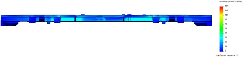
The distribution of equivalent (von Mises) stresses in the UzTE16M locomotive frame is shown in Fig. 4. The FEM analysis revealed a maximum equivalent stress of approximately 127 MPa, which is well below the yield strength limit of 235 MPa, confirming that the structure operates entirely within the elastic range. The highest stress concentrations were observed in the central cross-beam and at the junctions of longitudinal and transverse members, corresponding closely to the regions of maximum experimental deflection and the lowest stiffness.
Fig. 4Side-elevation von Mises stress distribution of the UzTE16M locomotive frame under a 40-ton static load (MPa)
The correlation between experimental deflection data and FEM-predicted stress-strain fields demonstrated strong agreement, with numerical deflection values differing by less than 5 % from the measured results ( 3.1 mm, 6.1 mm, 10.9 mm). This close correspondence validates both the experimental methodology and the computational model.
Overall, the combined experimental and FEM results confirm that the UzTE16M frame maintains adequate stiffness and strength under static loading. The FEM visualization also identifies localized stress concentration zones that may become critical under cyclic or fatigue loading, providing essential guidance for long-term monitoring and reinforcement planning.
6. Conclusions
The experimental investigation of the UzTE16M locomotive frame under static loading confirmed that its deflection behavior remained elastic and within the permissible 15 mm limit specified in repair standards. Residual deflections of 2-6 mm indicated no critical permanent deformation, while stiffness values ranged from 6.25-6.47 t/mm at the sides to 4.54-4.76 t/mm at the center, decreasing to 3.57 t/mm at higher loads, revealing localized stress concentration. Frame No. 019 showed slightly greater deflections, suggesting local weakening and the need for monitoring or reinforcement.
Finite element (FEM) validation under identical boundary and loading conditions confirmed the experimental results with less than 5 % deviation. The UzTE16M frame operated entirely within the elastic range, with maximum von Mises stresses of 127 MPa, well below the 235 MPa yield limit, verifying the accuracy of both experimental and numerical approaches.
The novelty of this research lies in the integration of full-scale experimental testing with FEM modeling to assess stiffness and residual deflection in a modernized locomotive frame. This combined approach provides a comprehensive basis for diagnosing real structural behavior, identifying critical stress zones, and supporting condition-based maintenance strategies.
The proposed methodology offers a reliable framework for evaluating the residual service life and defining repair criteria. Future research should expand the approach to include dynamic and fatigue loading, implement digital twin technologies for real-time structural monitoring, and apply probabilistic models to improve the accuracy of service life predictions.
References
-
C. Ji, S. Sun, Q. Li, Z. Ren, and G. Yang, “Realistic fatigue damage assessment of a high-speed train bogie frame by damage consistency load spectra based on measured field load,” Measurement, Vol. 166, p. 108164, Dec. 2020, https://doi.org/10.1016/j.measurement.2020.108164
-
B. J. Wang, S. Q. Xie, Q. Li, and Z. S. Ren, “Fatigue damage prediction of metro bogie frame based on measured loads,” International Journal of Fatigue, Vol. 154, p. 106532, Jan. 2022, https://doi.org/10.1016/j.ijfatigue.2021.106532
-
F. Guo, S. Wu, J. Liu, X. Wu, and W. Zhang, “An innovative stepwise time-domain fatigue methodology to integrate damage tolerance into system dynamics,” Vehicle System Dynamics, Vol. 61, No. 2, pp. 550–572, Feb. 2023, https://doi.org/10.1080/00423114.2022.2051567
-
O. Khamidov, A. Yusufov, S. Jamilov, and S. Kudratov, “Remaining life of main frame and extension of service life of shunting Locomotives on railways of Republic of Uzbekistan,” in E3S Web of Conferences, Vol. 365, p. 05008, Jan. 2023, https://doi.org/10.1051/e3sconf/202336505008
-
A. Yusufov, O. Khamidov, N. Zayniddinov, and S. Abdurasulov, “Prediction of the stress – strain state of the bogie frames of shunting locomotives using the finite element method,” in E3S Web of Conferences, Vol. 401, p. 03041, Jul. 2023, https://doi.org/10.1051/e3sconf/202340103041
-
S. Kudratov, A. Yusufov, O. Khamidov, and S. Samatov, “Diesel locomotives – Fault analysis and problem solving,” in The 3rd International Symposium on Civil, Environmental, and Infrastructure Engineering (ISCEIE) 2024, Vol. 3317, p. 060013, Jan. 2025, https://doi.org/10.1063/5.0266930
-
S. Abdurasulov, N. Zayniddinov, O. Khamidov, A. Yusufov, and S. Jamilov, “Stress-strain state analysis of cross beam of main frame of industrial electric locomotives PE2M and PE2U,” in The 3rd International Symposium on Civil, Environmental, and Infrastructure Engineering (ISCEIE), Vol. 3317, p. 060011, Jan. 2025, https://doi.org/10.1063/5.0266927
-
S. Abdurasulov, N. Zayniddinov, A. Yusufov, and S. Jamilov, “Analysis of stress-strain state of bogie frame of PE2U and PE2M industrial traction unit,” in E3S Web of Conferences, Vol. 401, p. 04022, Jul. 2023, https://doi.org/10.1051/e3sconf/202340104022
-
A. Grishchenko, A. M. Yusufov, and D. N. Kurilkin, “Forecasting the residual service life of the main frame and extending the service life of shunting locomotives JSC “UTY”,” in E3S Web of Conferences, Vol. 460, p. 06032, Dec. 2023, https://doi.org/10.1051/e3sconf/202346006032
-
R. Rahimov and D. Zafarov, “Justification of the possibility for extending the service life of cast parts of a three-axle bogie based on results of the running strength tests to determine their loading,” Communications – Scientific letters of the University of Zilina, Vol. 27, No. 3, pp. B170–B185, Jul. 2025, https://doi.org/10.26552/com.c.2025.035
-
R. V. Rahimov, F. F. Khikmatov, D. S. Zafarov, and F. S. Galimova, “Conversion of a passenger wagon into a dynamometric wagon for railways of the Republic of Uzbekistan,” in 6th International Conference for Physics and Advance Computation Sciences: ICPAS2024, Vol. 3282, p. 070002, Jan. 2025, https://doi.org/10.1063/5.0266047
-
H. Sang et al., “Development of a measuring instrument to investigate wheel-rail adhesion characteristics,” Engineering Failure Analysis, Vol. 153, p. 110164, 2025.
-
K. Zhou, T. You, D. Gong, and J. Zhou, “Effects of uncertain suspension parameters on dynamic responses of the railway vehicle system,” Probabilistic Engineering Mechanics, Vol. 71, p. 103405, Jan. 2023, https://doi.org/10.1016/j.probengmech.2022.103405
-
E. S. Oganyan, G. M. Volokhov, A. S. Gasyuk, and D. M. Fazliakhmetov, “Calculated experimental evaluation of the operating life of basic locomotive parts for ensuring their safe operation,” Journal of Machinery Manufacture and Reliability, Vol. 47, No. 2, pp. 155–159, Apr. 2018, https://doi.org/10.3103/s1052618818020097
About this article

The authors have not disclosed any funding.
The datasets generated during and/or analyzed during the current study are available from the corresponding author on reasonable request.
The authors declare that they have no conflict of interest.
