Abstract
This article originally integrates an approach to turbo-compressor analysis, combining performance evaluation with modern diagnostic tools, and offers a fresh perspective that distinguishes your work from more conventional studies. Significantly, the research topic of turbo-compressor maintenance is of paramount importance to industrial efficiency and reliability and its exploration of this area contributes valuable knowledge to the field. Overall, the current organization is very easy to understand and logically structured. The paper proposes a comprehensive framework for intelligent maintenance and performance optimization of industrial turbo-compressors. The core contributions include, firstly, establishing a graphical framework linking mechanical analysis of key compressor components (impeller/rotor/seals/bearings) with real-time condition monitoring; secondly, integrating vibration analysis, oil analysis, temperature/pressure monitoring, and machine learning algorithms for fault prediction; and finally, specifying test procedures such as hydrostatic testing, over-speed testing, and mechanical run testing.

Highlights
- Turbo-compressor maintenance is of paramount importance to industrial efficiency and reliability and its exploration of this area contributes valuable knowledge to the field.
- Establishing a graphical framework linking mechanical analysis of key compressor components (impeller/rotor/seals/bearings) with real-time condition monitoring.
- Integrating vibration analysis, oil analysis, temperature/pressure monitoring, and machine learning algorithms for fault prediction.
- Specifying test procedures such as hydrostatic testing, overspeed testing, and mechanical run testing.
- Current organization is strongly easy to understand and logically structured.
1. Introduction
While many studies separately address the mechanical design or condition monitoring of turbo-compressors, this work uniquely bridges both aspects by offering an integrated, risk-informed framework for evaluating performance and guiding maintenance practices. It introduces a visualized, component-level analysis combined with real-time condition monitoring insights, providing engineers with a comprehensive strategy to enhance operational efficiency. Industrial turbo-compressors play a critical role in various sectors, including oil and gas, petrochemical, and power generation industries. These machines are essential for compressing gases to higher pressures, ensuring efficient energy transfer and process optimization. The performance, reliability, and efficiency of turbo-compressors depend on various factors, including design parameters, aerodynamic behavior, and effectiveness of maintenance strategies. As industrial demands grow, advanced maintenance and repair methodologies, such as predictive maintenance, vibration analysis, and real-time condition monitoring, have become crucial in minimizing downtime and operational expenses. This paper provides in-depth insights into the key components of industrial turbo-compressors, their performance characteristics, and modern maintenance approaches aimed at optimizing their lifespan and efficiency. We briefly describe the causes of failure and defects of turbo-compressors, as well as the actual methods of repairing worn-out parts. The essence of developed technology of turbo-compressor repair using the electro-spark method is stated [1]. This paper introduces a new spectral analysis control approach for monitoring and diagnosing malfunctions in turbo compressors to enable predictive maintenance strategies and enhance the reliability of critical industrial machinery [2]. The book covers the installation, maintenance, and repair of major process equipment, including pumps, blowers, compressors, power transmission equipment, and electric motors, as well as general preventive and predictive maintenance topics [3]. This work is a reference for machinery engineers concerned with machinery and component installation, maintenance, and repair [4]. The fourth volume of a textbook on the maintenance and repair of marine diesel engines, focusing on the design, maintenance, and repair of turbochargers and air coolers [5]. Dry screw compressors for process gas applications, including selection parameters, capabilities, limitations, and maintenance considerations [6]. The paper discusses the maintenance planning for a centrifugal compressor (K-6801 B) at PT. Perta Arun Gas, which was experiencing issues such as decreased discharge pressure, excessive vibration, high temperature, and noise, indicating potential damage to the compressor components [7]. This paper presents a review of the latest research on machining and repairing methods for turbomachinery components, which often have complex geometries and are made of difficult-to-machine materials [8]. The paper provides an overview of the operating and control philosophy of turbo-compressors, which are widely used in the process industry [9]. A reference book and CD-ROM that covers the full spectrum of information needed for an individual to select, operate, test, and maintain axial or centrifugal compressors, including basic aerodynamic theory, troubleshooting guidelines, and example problems and reference data [10]. This handbook covers component failures, maintenance methods, and repair techniques for various mechanical systems [11]. The Maintenance Engineering Handbook covers a wide range of topics related to the organization, management, and technical aspects of maintenance in industrial settings [12]. This book provides a comprehensive overview of gas turbine engineering, including chapters on maintenance techniques for turbo-compressors [13]. This paper provides a practical guide to compressor technology, covering both positive displacement and dynamic compressors in detail, including their theory, design, performance, monitoring, control, and asset management considerations [14]. This paper covers the use of gears in turbomachinery applications, reviews relevant industry standards, discusses gear failure modes and prevention, and describes various repair techniques that can save downtime and costs [15]. This paper presents current findings of an ongoing program to evaluate factors that contribute to reciprocating compressor reliability [16]. This handbook provides a comprehensive guide to the theory, construction, operation, inspection, maintenance, and testing of large turbo-generators [17]. Compressor stages with enhanced map width have been developed to address the limited operating range of conventional centrifugal compressors used in turbochargers [18]. This paper provides an overview of the key rotor-dynamic considerations in the design and analysis of turbomachinery, including topics such as vibration, critical speeds, balancing, bearings, and instability [19]. Centrifugal compressor research and development have been revolutionized through the use of computational fluid dynamics to better understand the flow and physical phenomena involved [20]. Review of turbine technology, including thermodynamics, compressible fluid mechanics, fundamental turbine concepts, and velocity diagram design [21]. The paper discusses the importance of material selection and maintenance in gas turbine components and how these factors impact the lifecycle cost and performance of gas turbines [22]. While previous studies have extensively examined the fundamental principles and operational characteristics of turbo-compressors, ongoing advancements in predictive maintenance, condition monitoring, and optimization techniques necessitate further exploration. This study aims to bridge the gap between theoretical analysis and practical implementation by providing a comprehensive evaluation of turbo-compressor components, their performance metrics, and innovative maintenance strategies. By integrating modern diagnostic tools such as vibration analysis, temperature monitoring, and machine learning-based fault detection, this research seeks to enhance the reliability, efficiency, and longevity of industrial turbo-compressors. The insights presented in this paper will serve as a valuable resource for engineers, researchers, and industry professionals striving to develop smarter maintenance and repair solutions. While existing literature has explored individual aspects of turbo-compressor performance and maintenance, this study uniquely integrates practical industrial insights with a systematic risk-based approach. By offering a comprehensive analysis of key component failures, maintenance challenges, and their impact on operational efficiency, our research provides an advanced framework for smarter maintenance strategies. This novel perspective enhances the ability of engineers to anticipate failures, optimize repair schedules, and reduce unplanned downtimes, setting a new standard in industrial turbo-compressor maintenance. The main contribution of this study lies in its holistic approach – linking the theoretical understanding of compressor dynamics with modern maintenance technologies such as online monitoring systems and data-driven diagnostics. This fusion enables smarter, predictive repair strategies for critical equipment in high-stakes industries. Additionally, the graphical representations and structured breakdown of compressor components offer an intuitive guide for both researchers and field engineers, distinguishing this paper from traditional reviews or case studies. To enhance clarity and improve the logical progression of the manuscript, the content has been reorganized to follow a structured and focused development flow. The revised background section now includes only the essential compressor principles necessary to support the later modeling and maintenance discussions. The subsequent section summarizes the relevant sensing technologies and data preprocessing considerations used in condition-based monitoring. The core contribution of this work, the proposed hybrid digital-twin framework for turbo-compressor maintenance, is then presented in detail. Following this, a validation strategy based on publicly available datasets and reproducible simulation procedures is introduced to demonstrate the applicability of the approach. Finally, the manuscript concludes with practical implementation recommendations and future research directions.
2. Compressor background
Compressors are crucial tools in oil, gas, and petrochemical industries, compressing air flow from low-level to high-level pressure. Similar to turbines, compressors have similar parts and mechanisms but are mainly identical in various industries (see Fig. 1).
Fig. 1Design test of compressor performance, (a) front view, (b) top view. Photographs taken by the corresponding author in a controlled laboratory environment during the course of this research (2024)

a)

b)
Under rotary machines, specialized rails are installed to support and test the equipment under various operational conditions. These rails are designed to withstand significant loads and torques generated during machine operation. For further clarification, reference [23] provides a detailed mechanical analysis of this structure, including various loading scenarios and support conditions applied beneath the testbed framework.
2.1. Gas compressor
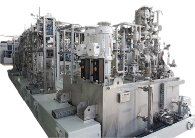
A gas compressor is a mechanical device that reduces the volume of an input gas flow to increase its pressure. Similar to pumps, compressors can move fluid through a pipe and raise pressure on the fluid. The main job of a pump is to pressurize and move liquids that can't be compressed. They compress gases and make them take up less space. Hermetic and semi-hermetic compressors combine the compressor and motor driving, operating within the compressed gas envelope. Hermetic compressors have a single impermeable steel casing, requiring replacement in case of failure, while semi-hermetic systems have a sizable cast metal casing with operable gasketed covers. Open compressors can run on non-electric power sources like turbines or internal combustion engines (see Fig. 2).
Fig. 2Powertrain of the compressor a) motor, b) gearbox. Photographs taken by the corresponding author in a controlled laboratory environment during the course of this research (2024)

a)

b)
2.2. Axial-flow compressors
Axial-flow compressors, also known as dynamic rotating compressors, compress working fluid through fan-like airfoil arrays. Axial-flow compressors are utilized in applications requiring compact designs or high flow rates because of their efficiency in these areas. The revolving airfoils accelerate the fluid, while stationary airfoils slow it down for subsequent stages (see Fig. 11(b)).
2.3. Centrifugal compressors
Centrifugal compressors are used in industries like natural gas processing, petrochemical, and oil refineries to force gas to the impeller’s rim. They use a revolving disk or impeller, with a diffuser section converting velocity energy into pressure energy (see Fig. 3 and Fig. 11(a)).
Fig. 3Different types of the compressor’s split casing a) horizontally, b) radially, c) vertically, Photographs taken by the corresponding author in a controlled laboratory environment during the course of this research (2024)

a)

b)

c)
2.4. Casing and cover
The casing and cover, which contain the rotor, intake, and discharge connections, are immovable parts that hold pressure. For radially split machines, the outer casing should house inlet and outlet connections, while process intake connectors on overhung design machines can be located in the end head.
2.5. Guide vane
It can fix or adjust the guiding vanes, or stationary components, to supply the impeller’s gas intake with the required flow direction. When the adjustable guide valves predictably adjust the compressor's performance when it runs at constant speed, single-stage designs with moderate to high flow and adjustable guide vanes work very well.
2.6. Rotor
The rotor can be designed as a beam-style or overhung variant. An overhung rotor design places the impeller outside the bearing support system, while a beam-style design places the impeller(s) in between the journal bearings (see Fig. 4).
Fig. 4Rotor sections of compressor. Photographs taken by the corresponding author in a controlled laboratory environment during the course of this research (2024)


2.7. Overhung rotor
Some of the distinct goals include the most efficient aerodynamic arrangement; low-speed operation restricted to single-stage configurations; optimal access for carrying out maintenance operations; larger parasitic losses; and overhung rotor design.
2.8. Beam-style design
This design must consider certain aspects, such as the maximum head flexibility with re-staging capabilities, the minimal beginning torque needed, the low parasitic losses, the requirement for two or more stage configurations, and the somewhat reduced efficiency due to thrust balance losses.
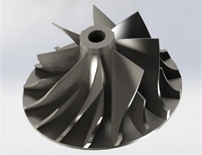
2.9. Impeller
The main function of a compressor is to strike the gas rapidly, increasing its velocity and momentum. This increase in impeller pressure accounts for two-thirds of the compressor’s total pressure and typically uses closed, semi-closed, or open impellers (see Fig. 5).
2.10. Thrust balance piston
On the beam-style rotor’s discharge end, the balance drum comes after the final impeller. The thrust balance piston’s size is determined by the overall thrust created by the impeller while it is operating.
2.11. Diaphragm
It is a stationary element that sits between a multi-stage compressor’s various stages. To convert kinetic energy to pressure energy between stages, the diaphragm precisely regulates the direction and flow of gas through the compressor (see Fig. 6).
Fig. 5Closed types of impellers, a), b) semi-closed, c), d) closed. Photographs taken by the corresponding author in a controlled laboratory environment during the course of this research (2024)

a)

b)
c)

d)
Fig. 6a) Thrust balance piston, b) compressor’s diaphragm. Photographs taken by the corresponding author in a controlled laboratory environment during the course of this research (2024)

a)

b)
2.12. Collector
The collector slows down the gas stream from the diffuser, releasing it into an end diffuser or discharge nozzle. There are two types: volute and plenum, with volute booster designs being preferred due to their efficiency advantage.
2.13. Bearing
The bearing system consists of a journal and thrust bearings (see Fig. 7).
2.14. Journal bearing
A journal bearing is a cylinder containing fluid lubrication that surrounds the shaft and supports it, avoiding metal-to-metal contact. Oil is the most commonly used fluid, and hydrodynamic principles create an oil wedge that moves the shaft within the bearing clearances. Journal bearings offer greater damping than rolling-element bearings, with stronger and more viscous lubricant coatings providing better damping capabilities. The bearing’s stability increases with available dampening, maintaining the rotor's fixed attitude angle and reducing vibration transfer. Pressure distribution within a complete journal bearing is rapid, with the minimum pressure varying depending on factors like bearing dimensions, speed, load, oil viscosity, and supply pressure. Thrust bearings prevent the rotating shaft from moving axially, ensuring the precise axial position of the rotor assembly within the compressor. Thrust load and the diameter of the thrust balance drum are considered when sizing the thrust bearing.
Fig. 7Compressor’s bearings, a) journal, b) thrust. Photographs taken by the corresponding author in a controlled laboratory environment during the course of this research (2024)

a)

b)
2.15. Seals
The four primary types of seals used are O-ring seals, labyrinth seals, oil film seals, and dry gas seals.
2.15.1. O-ring seals
Static seals of the O-ring variety are utilized as necessary. The O-ring seals the gap between two immovable parts (the case and cover, for example) and stops leaks. It can be made of rubber or synthetic material (see Fig. 8).
Fig. 8Fluid sections of compressor, a) seal gas panel, b) O-ring seals. Photographs taken by the corresponding author in a controlled laboratory environment during the course of this research (2024)

a)

b)
2.15.2. Labyrinth seals
In their most basic form, labyrinth-type seals are a means of limiting gas loss without requiring contact between the stationary compressor casing component and shaft.
2.15.3. Oil film seals
The purpose of the oil film seal is to prevent compressed gas leaks into the atmosphere. The sealing is achieved by using an extremely thin, high-pressure oil film under a free-floating cylindrical ring, since even tiny amounts of natural gas leakage are unacceptable (see Fig. 9).
Fig. 9Gas seal panel of compressor, a) oil system, b) junction box, c) instrument. Photographs taken by the corresponding author in a controlled laboratory environment during the course of this research (2024)
a)

b)

c)
2.15.4. Dry gas seals
Shaft sealing is crucial for turbo-compressors in process gas service to prevent uncontrollable gas from exiting the compressor case and entering the atmosphere. Multi-stage beam-style compressors require two seals, while single-stage overhung compressors require a single seal behind the impeller (see Fig. 10).
Fig. 10Dry gas seals. Photographs taken by the corresponding author in a controlled laboratory environment during the course of this research (2024)

The dry gas face seal is a face-type seal that uses dry, clean gas instead of the seal oil system. It evacuates a small amount of gas to a safe atmosphere for cooling. Tandem-style seals, consisting of a main seal and a secondary seal, are typically used for process gas service. The secondary seal serves as a backup in case of primary seal failure, while the primary seal absorbs the entire pressure drop. To predict the replacement interval for dry gas seal (DGS) rings, manufacturers often define a “lift-off speed” – the minimum rotor speed at which gas film is established to prevent contacting wear [8]. The replacement cycle formula for dry gas seal rings is as follows:
where Lift-off Speed is the minimum shaft speed (rpm) at which the gas film fully separates seal faces, Safety Margin Factor is a coefficient (typically 1.1-1.3) accounting for variations in load, contamination, and wear, and Mean Operating Speed is the average shaft speed during normal operation (rpm).
Fig. 11Standard compressor illustrating nomenclature of essential components [42]
![Standard compressor illustrating nomenclature of essential components [42]](https://static-01.extrica.com/articles/25400/25400-img24.jpg)
a) Centrifugal
![Standard compressor illustrating nomenclature of essential components [42]](https://static-01.extrica.com/articles/25400/25400-img25.jpg)
b) Axial
3. Parameters for selection of compressor
To choose an appropriate compressor, one must consider several factors, including the application, gas handling and analysis, flow rate, suction pressure, suction temperature, discharge pressure, drive system, NTP conditions, and STP conditions. The NTP conditions (Nm3/hr) at the ocean level should be 1.033 kg/cm2A, 273 K, 0 % r.h., while the STP conditions should be sm3/hr at the ocean level, 288 K, 0 % r.h.
3.1. Aerodynamic performance of compressor
There are two methods to calculate a compressor’s aerodynamic performance:
– Adiabatic method.
The pipeline compressor industry accepts the adiabatic calculation method, which is an isentropic or constant entropy process. By definition, the adiabatic process prevents heat transfer from occurring in the system, so entropy does not change. Since there is a tiny amount of heat loss via the casing, this assumption is merely an acceptable estimate for small pressure ratios and not an accurate theory that holds true for very small pressure ratios.
– Polytropic method.
The polytropic method is the industry-standard calculation approach for compressors with numerous stages and large compression ratios. A polytropic process incurs heat losses, requiring more energy to operate with the gas for the same duration. The heating effect is caused by gas friction, turbulence, conduction, or radiation. The polytropic efficiency and the gas exponent determine how much of these losses occur.
– Surge.
A surge, or flow instability, is a common issue in centrifugal compressors when the compressor cannot generate enough head to overcome downstream resistance, leading to reversal of flow. Suction flow deficiency can also induce surges. Symptoms include rapid flow reversal, severe vibration, increased temperature, noise, and potential compressor trip. Surges can also lead to decreased output, compressor life, efficiency, and mechanical damage.
– Surge control.
To control surge, the anti-surge valve typically circulates some or all of the compressor discharge. Engineers design certain compressor systems to continuously recycle a specific percentage of the flow. Although it wastes energy, this method of managing the compressor may work well.
– Anti-surge valve.
The anti-surge valve is a fail-open solenoid valve that requires a low 4 mA signal to open and a high 20 mA signal to close. When a failure occurs, it opens, ensuring the safe position. The control valve, the system’s actuator, sends pressurized fluid back to the compressor, lowering plenum pressure and preventing low flow.
– Choke
Choke occurs when flow velocity increases for high-speed equipment, typically approaching sonic speed during the compressor stage. For slower equipment, losses increase until the pressure ratio approaches 1:1, preventing a choke. In this case, the flow changes minimally despite a sharp drop in the speed line’s pressure ratio, often due to impeller or diffuser velocities (see Table 1).
Table 1Different types of tests’ compressor
Necessary test | Optional test |
Hydrostatic | Performance |
Over speed | Helium |
Mechanical running | Sound level |
Assembled machine gas leakage | Complete unit |
4. Mechanical running test
The mechanical running test involves a machine with contracted shaft seals and bearings, following the vendor’s instructions. The machine should run at maximum continuous speed until the bearings, lube-oil temperatures, and shaft vibrations stabilize. The speed increments should be around 10 %. After increasing the speed to the trip rate, the machine should run for at least fifteen minutes and then for four hours. The test instrumentation must function satisfactorily and measure unfiltered vibration within specified limits. After the test, remove, examine, and reassemble each bearing. Mechanical running tests were used to characterize dynamic behavior across the normal operating envelope and at representative load points. Before tests, shaft alignment and coupling conditions were verified by laser alignment; static and dynamic balancing were confirmed to meet the specified balance grade (e.g., ISO 1940 G, appropriate for the machine). The run protocol included controlled run-ups, coast-downs, and steady holds at 25 %, 50 %, 75 %, and 100 % of the rated speed, as well as at any specified operating points under load. Each steady hold lasted long enough (typically ≥ 30 minutes) to reach thermal and dynamic equilibrium; transient ramps were limited to manufacturer-recommended rates. Monitored variables included shaft displacement (proximity probes), casing and bearing vibration (accelerometers), shaft speed (encoder), torque (torque transducer or torque meter where available), bearing and oil temperatures (thermocouples, 1 s logging), and oil pressure/flow; all channels were recorded by a multi-channel DAQ (24-bit resolution where available) with sampling rates selected per channel (≥10 kHz for vibration, 1 kHz for displacement and speed, 1 Hz for temperature/pressure). Data processing used anti-aliasing filters and synchronized time stamps to allow spectral (FFT), orbit, and time-domain analysis. Acceptance criteria included stable vibration and shaft centerline within design limits, steady bearing temperatures within expected ranges, no unusual torque or power signatures, and no sustained trends indicating degradation [24-29].
– Assembled compressor gas leakage test.
The vendor and buyer must pressurize fully assembled compressor casings for poisonous, dangerous, or flammable duty, maintaining maximum sealing pressure for at least half an hour and checking for gas leaks.
– Performance test.
The compressor must meet ASME PTC-10 performance testing standards, with a minimum of five points at regular speed, and power not exceeding 104% of the vendor's estimated shaft power value.
– Helium test.
Test the compressor casing for gas leaks using helium at maximum pressure, submerging it in water for at least half an hour, and maintaining constant pressure. The buyer may authorize an alternative test.
– Complete unit test.
The unit’s completeness depends on a mechanical running test that includes auxiliary parts, gears, compressors, and drivers, and may require additional torsional vibration measurements with the buyer’s consent.
– Hydrostatic test.
Hydrostatic testing is required for pressure-sensitive parts, using liquid at a maximum working pressure of 140 kPa gauges. The test should last at least half an hour to make sure there are no leaks or seepage. For large, heavy castings, the buyer and seller should agree on longer times. Hydrostatic tests were performed to verify the pressure integrity of compressor casings and pressure-containing components. A servo-controlled hydraulic test pump was used to pressurize the assembly with de-aerated water (with a corrosion inhibitor added) while all vents were open to purge trapped air. Test pressure was set to 1.25-1.5 × the maximum allowable working pressure (MAWP) of the component in accordance with standard practice; the target pressure was approached in controlled increments (≈10 % of the target pressure per minute) and held for 10 minutes at the final pressure while data were recorded. Pressure was measured with a calibrated digital pressure transducer (traceable calibration, accuracy ±0.25 % FS). Displacement and a permanent set of accessible surfaces were monitored visually and with dial indicators where applicable. Acceptance criteria: no visible leakage, no permanent deformation, and no pressure drop greater than the transducer accuracy during the hold period. Safety devices included a burst/pressure relief disk and remote monitoring of pressure by trained personnel.
– Overspeed test.
Impellers must undergo an overspeed test at 115 % of their maximum speed for a minute, measuring the bore, eye seal, and outside diameter. Post-test measurements must be documented and provided to the purchaser for study. Over-speed testing was carried out on the assembled rotor and driveline to verify mechanical integrity at speeds above normal operation. Rotational speed control was provided by a variable-frequency drive (VFD) coupled to the test motor (or by the turbine drive as applicable); shaft speed was measured with an optical encoder/tachometer (resolution ≥ 1 pulse per rev). Tests followed a stepped profile: run-up to 90 % rated speed to verify baseline behavior, then incremental increases (e.g., 100 %, 110 % and, when permitted by design, 120 % of rated speed). Typical ramp rates were limited to ≈ 5 % of the rated speed per second, and each over-speed dwell was maintained for 60-120 seconds to observe transient and steady behavior. The rotor and bearings were instrumented with proximity (eddy-current) probes for shaft displacement, IEPE accelerometers for vibration (instrumentation and DAQ configured with sample rates ≥ 10 kHz for vibration channels and synchronized to speed), and bearing temperature/thermocouples logged at 1 Hz. Emergency shutdown interlocks, a safety containment enclosure, and visual/remote observation were used to ensure safe operation. Acceptance criteria: no rubs, no sudden step changes in vibration or displacement, and no evidence of bearing distress or loss of balance.
5. Condition and health monitoring
In the centrifugal compressors, conditional and healthy data play a main role in engineering aspects such as reliability, efficiency, and safety, which employ various technological methods to monitor key factors and detect critical issues in a timely manner.
– Vibration analysis.
Real-time signals from vibro-acoustic sensors should help vibrational monitoring determine mechanical faults, imbalances, misalignments, bearing problems, and other problems.
– Temperature monitoring.
Two popular methods for detecting the temperature of the centrifugal compressors are used: firstly, by looking at crucial zones, such as discharge, seal, and bearing, and secondly, by infrared thermographic methods that are non-contact monitoring.
– Oil analysis.
Oil analysis reveals information especially related to gears and bearings due to wear particles, pollution, and leakage, particularly in gears and bearings.
– Pressure monitoring.
Determining the performance of the centrifugal compressor's pressure, suction, and discharge pressure is useful for monitoring flow in the impeller or seal clearance.
– Gas Composition Analysis (GCA).
GCA must analyze compressors with upstream operations or internal damaged parts due to compression flows.
5.1. Critical vibration monitoring thresholds
To enhance the clarity and usefulness of Section 1.23, we recommend incorporating specific thresholds informed by international standards and best practices:
1) ISO 10816-3 Vibration Severity Levels.
For industrial machines (15 kW-15,000 RPM), measured at bearing housings under normal conditions, vibration velocity thresholds are defined as follows [1], [2]:
– Newly commissioned machinery (ideal condition): ≤ 0.08 in/s pk (≈ 1.4 mm/s rms).
– Unrestricted operation (acceptable): ≤ 0.16 in/s pk (≈ 2.8 mm/s rms).
– Restricted operation (maintenance needed): 0.16-0.25 in/s pk (≈ 2.8-4.5 mm/s rms).
– Damage imminent (shutdown required): > 0.25 in/s pk (≈ 4.5 mm/s rms).
2) API-670 Machinery Protection Standards.
For critical rotating equipment like centrifugal compressors, it's standard to install at least two axial and two radial proximity probes, plus seismic sensors on the bearing housing, to measure shaft and casing vibrations [3].
3) Empirical Shock Threshold Settings.
Reciprocating machines often use accelerometer-based shock-monitoring systems with threshold settings defined relative to RPM [4]:
– Lower shock threshold (AL): approximately RPM / 80 in g’s (peak acceleration).
– Upper shock threshold (AH): approximately RPM / 50 in g.
These quantitative thresholds provide a clear operational framework for alarm levels, maintenance scheduling, and machine protection strategies [30-32].
5.2. Vibration signature analysis
Vibration signature analysis, known as algorithms of machine learning, is an indicator of failures in mechanical systems because of its intelligent abilities to predict and detect faults before stopping time.
– Ultrasound Monitoring.
Ultrasound sensors monitor mechanical problems in sealing systems and bearings in high-frequency performance, such as leaks, friction, and electrical discharge.
– Rotor Dynamics Analysis.
Examining the rotor's behavior helps identify critical velocities and instabilities using various rotor dynamics methods that can detect resonance, imbalance, shafts, and impellers.
– Online Monitoring Systems.
Different sensors and datasets combine with online monitoring tools to display the compressor’s health. This strategy can also predict maintenance status.
– Condition-Based Maintenance (CBM).
A technique for CBM maintenance to complete the operations depends on the real condition of the machinery. Industries that reduce downtime and maximize maintenance efforts are the most important features.
6. Practical implementation guidance
6.1. Performance analysis of turbo-compressors
The design, operating conditions, and maintenance strategies of industrial turbo-compressors directly influence their efficiency and reliability. The results of this study highlight the significance of key components such as impellers, rotors, seals, and bearings in determining overall compressor performance. Testing methodologies, including hydrostatic, over-speed, and mechanical running tests, demonstrate that a well-maintained compressor exhibits lower vibration levels, enhanced aerodynamic efficiency, and an extended operational lifespan. The aerodynamic performance assessment, utilizing both adiabatic and polytropic methods, confirms that polytropic efficiency provides a more accurate representation of real-world compressor behavior, particularly in multi-stage configurations. The results also indicate that surge and choke conditions remain critical challenges, with anti-surge control mechanisms playing a vital role in preventing operational failures.
6.2. Impact of condition monitoring on maintenance optimization
Condition monitoring techniques such as vibration analysis, temperature monitoring, and oil diagnostics have proven essential in identifying early signs of mechanical failures. The results of the vibration signature analysis show that imbalances, misalignments, and bearing wear are among the most common failure modes in turbo-compressors. Implementing real-time monitoring and predictive maintenance can significantly reduce downtime, resulting in enhanced system reliability and cost savings. Oil analysis has further demonstrated its effectiveness in detecting contamination and wear particles, especially in gears and bearings. The findings suggest that proactive lubricant management prevents unexpected failures and extends component life by minimizing friction and heat generation.
6.3. Effectiveness of modern maintenance strategies
The integration of machine learning algorithms and online monitoring systems has shown promising results in fault detection and preventive maintenance. Data-driven analysis enables operators to predict failures before they occur, reducing emergency shutdowns and improving overall system efficiency. The study results show that condition-based maintenance (CBM) is a better option than traditional scheduled maintenance because it lets repairs be made based on the actual condition of the equipment instead of fixed time intervals. Additionally, advanced sealing technologies, including dry gas seals and labyrinth seals, have exhibited improved performance in minimizing gas leakage and enhancing compressor efficiency. The results confirm that selecting the appropriate sealing mechanism can significantly reduce operational losses and environmental emissions.
6.4. Challenges and future considerations
Despite advancements in compressor technology and maintenance techniques, certain challenges persist. The primary limitations identified in this study including:
– Complexity in predictive maintenance implementation, requiring skilled personnel and significant investment in data analytics.
– Environmental and energy efficiency concerns, where further research is needed to develop more sustainable and energy-efficient compressor designs.
– Integration of AI-based fault detection, which requires extensive datasets to improve accuracy and reduce false positives in anomaly detection.
Future research should focus on enhancing AI-driven condition monitoring, developing more robust materials for critical compressor components, and optimizing energy efficiency in large-scale industrial applications. Our methodology can deliver substantial industrial advantages across key areas:
– Optimizing Maintenance Schedules.
By transitioning from fixed-time maintenance to condition-based decision-making, our approach enables better timing of interventions – with documented impacts including up to a 40 % reduction in maintenance costs and a 1.8 percentage point decrease in downtime [33].
– Enhancing Fault Diagnostics.
In studies of high-pressure industrial compressors, hybrid clustering techniques improved failure detection accuracy by 4.9 % on average and reduced training time by 23 %. Such improvements translate to fewer false alarms and faster detection times in practice [34].
– Improving System Reliability and Uptime.
Predictive maintenance (PdM) frameworks have been shown to reduce unplanned downtime by up to 50 %, boost equipment lifespan by 20-40 %, and improve overall operational reliability thanks to early fault detection and repair scheduling [35, 36].
Table 2Developments in turbo-compressor maintenance
Application area | Measurable benefit | Ref. |
Maintenance cost | Up to 40 % cost reduction | [33] |
Reduced downtime | ~1.8 % higher availability | |
Diagnostic accuracy | +4.87 % accuracy; −22.96 % training time | [34] |
Unplanned downtime | Up to 50 % reduction | [3] |
Asset lifespan | +20-40 % equipment life | [35, 36] |
– Concrete Case Data.
In a predictive maintenance study conducted on 150 wind turbines across six wind farms (total installed capacity: 283 MW), the proposed model successfully predicted anomalies up to two months before unscheduled downtime, with the real-time test confirming capability for early fault detection and proactive maintenance scheduling [37].
– Feature Engineering-Frequency-Domain Extraction.
Our methodology includes extracting frequency-domain features from vibration and sensor time-series data using techniques such as Fast Fourier Transform (FFT) and Power Spectral Density (PSD) analysis. Specific features, such as peak frequency amplitudes, band power, and harmonic ratios, are derived to capture characteristic signatures of faults (e.g., bearing defects, gear mesh frequencies) [38, 39]. We further apply Short-Time Fourier Transform (STFT) and Mel-Frequency Cepstral Coefficients (MFCCs) for time-frequency analysis, enabling detection of evolving operational states in rotating machinery [40].
Fig. 12Effective maintenance strategy

7. Validation strategy
This experiment introduces various flaws both pairwise and concurrently into the spinning system, then observing and analyzing the consequences of their interactions using FFT. The real representation of the rotating system under examination is shown first. Fig. 13 illustrates that each rotating system fundamentally comprises shaft elements, a motor, and bearings, but further components may be included. The test rig being examined features many disks affixed to the shaft, positioned between two bearings and at the shaft extremities.
Fig. 13Analogy of a turbo-compressor in a rotary system. Photograph taken by the M. Hasanlu in Sound and Vibration Research and Development Laboratory, PiezoSignal Co (2020)

The system was run under two primary conditions: a completely functional reference state and a defective state. In a healthy condition, bearings are presumed to be undamaged, the shaft is aligned with the motor axis, and no imbalanced masses are present on the disks. In the defective condition, for various scenarios, one or two functional bearings are substituted with malfunctioning bearings, the shaft is misaligned with the motor axis, and imbalance is induced by adding weights to the disks. Shaft misalignment was manifested in two unique forms: angular misalignment and offset (parallel) misalignment, relative to the motor axis. Shaft misalignment is a well-documented and critical flaw in industry that can adversely impact rotational and dynamic systems. The identified misalignment problems might cause shaft deflection and negatively impact overall system performance. Fig. 14 demonstrates that offset misalignment often results in vertical displacement of the shaft relative to the motor axis, while angular misalignment induces rotation of the shaft along the horizontal plane, causing it to tilt in relation to the motor axis.
Fig. 14Types of the misalignment in shaft and motor

a) Offset

b) Angular
Two geophone sensors were affixed to the bearings of the described rotating system to conduct the experiments. The bearing displacement signals were relayed through a data logger to a computer, where the vibration frequency-spectrum data for various test conditions were subsequently recorded and archived. The geophone positioned closest to the motor is designated as the left sensor, whilst the geophone situated farther from the motor is termed the right sensor – a differentiation that is distinctly evident in the plotted results. The aim was to evaluate the system under three distinct combinations of fault circumstances, which are summarized in Table 3.
Table 3Different conditions in rotary
Disk | Bearing | Shaft | Test |
Balanced | Healthy | Alignment | Ref |
Unbalanced | Damaged | Angular misalignment | Exp 1 |
Unbalanced | Damaged | Offset misalignment | Exp 2 |
Upon implementing the three conditions outlined in Table 3 and executing the system, the vibration frequency spectrum (FFT) data for each scenario were obtained from the geophone sensors and the data logger, then presented in LabVIEW. The Results section elucidates that the introduced defects can be discovered and anticipated by examining and comparing the FFT spectra of these situations based on their distinctive spectral outputs. The Results and Discussion section analyzes the impact of different fault circumstances on the vibration frequency spectra by FFT. The FFT spectra for each bearing at designated rotational speeds, as outlined in Table 3, are illustrated in Fig. 15 and 16. According to Fig. 15, the reference (healthy) case exhibits reduced maximum vertical shaft displacements at the left bearing (as measured by the left geophone) compared to the faulty cases. In the case of a sick bearing with shaft imbalance, angular misalignment results in greater maximum displacements compared to offset misalignment. In the case of angular misalignment, the most significant displacements occur at three times the fundamental rotational frequency, while for offset misalignment, the maximum responses for the left (near-motor) sensor are seen at one and four times the fundamental frequency. In Fig. 16, the right (more distant) sensor indicates that the transverse bearing displacement spectrum for offset misalignment significantly differs from that of angular misalignment. In all misalignment scenarios, a prominent 1× peak is seen due to the imbalance; the amplitude of the first harmonic is greater in cases of angular misalignment. The right-sensor FFTs display more pronounced fluctuations than those of the left sensor, with elevated peaks at higher harmonics at rising speeds, a feature ascribed to the sensor’s greater distance from the motor. In the instance of the right sick bearing with shaft imbalance, the offset-misalignment scenario exhibits greater displacements at the 4×, 6×, and 7× harmonics in comparison to the angular-misalignment scenario.
Fig. 15Frequency responses in right-side bearing

8. Digital twin framework
Beyond the horizon of the title of this article, that is, the framework of the digital twin can cover the above context for preventing failure and deficiency. In order to use ability of the artificial intelligence (AI) based on current article, due to technologies, knowledge, experts, research activities around the world, it is essentially asked about capabilities and role of the digital twin specifically in condition monitoring of turbo-compressors more efficiency. Because of this, these days the AIs predicts future events can optimize maintenance and opportunity costs as well. Accordance with, here, there are planned two prompts in AI proposes graphical outlooks in future into digital twin monitoring of turbo-compressors as given:
1) Futuristic industrial factory with a large turbo-compressor machine at the center. Beside it is a holographic 3D digital twin of the compressor showing internal parts and live data. Floating data graphs, charts and sensor icons illustrate predictive maintenance analytics. Technical illustration style with vibrant lighting and a clear, informative layout.
2) Highly detailed cross-section of an industrial turbo-compressor, with a transparent overlay of its digital twin model and real-time sensor data. Show maintenance engineers viewing the holographic twin on a tablet. Style: photorealistic engineering diagram with focus on clarity and precision.
Fig. 16Frequency responses in left-side bearing

This article tries to ask among AIs platforms that are freely used globally, such as ChatGPT, Google Gemini (GG), and Stable Diffusion Online (SDO) separately in order to use all AI’s competences to estimate smart predictive and maintenance deals for turbo-compressor based on digital twin. The prediction results of the AIs are shown in Fig. 17.
Fig. 17Futuristic smart industrial maintenance and repair of the turbo-compressors, a) SDO, b) GG, c) ChatGPT. Photograph taken by the corresponding author in AI platforms (2025)

a)

b)

c)
Fig. 17 presents an outlook on the digital twin monitoring of turbo-compressors in the coming decades. The digital twin can assess system performance by displaying states, inputs, outputs, and faults on monitoring screens, allowing experts on-site to enhance efficiency and accuracy during run-time. For instance, the digital twin can immediately identify and visualize faulty locations on a screen or tablet. Moreover, experts can remotely detect issues such as rotor noise or shock impacts. Therefore, the digital twin represents a practical concept that can effectively support maintenance and predictive operations, not only for turbo-compressors but also for a wide range of industrial machines and applications.
8.1. Proposed tools for the digital twin of a turbo-compressor
To establish a digital twin for smart monitoring of a turbo-compressor, and to address issues related to its operation, several proposed tools are recommended for implementing online monitoring both on-site and off-site. These tools are presented in relation to their corresponding technology, hardware, and software components.
8.1.1. Technological Tools
Based on current technology and advancing knowledge, the following tools are suggested:
1) Internet of Things (IoT) Sensors and Industrial Internet of Things (IIoT): This is how the real-time data is collected. High-precision sensors for vibration, temperature, pressure, and operational speed are embedded in the physical compressor. The IIoT network wirelessly transmits this data to the digital model.
2) 3D Reconstruction and Modeling Tools:
– CAD/BIM Software: Engineers start with the original Computer-Aided Design (CAD) files or Building Information Modeling (BIM) data to create the initial, precise 3D virtual model.
– Reality Capture: Techniques like LiDAR (Light Detection and Ranging) or Photogrammetry are used to create highly accurate "as-built" scans (point clouds) of the physical machine and its surroundings, ensuring the digital twin is geometrically precise to the real object.
– Gaussian Splatting: This is an emerging, highly efficient 3D reconstruction technique that can capture real-time spatial data and may be used for even higher-quality, real-time motion holograms of the machinery and environment.
3) Holographic Display Devices: Instead of traditional flat screens, specialized hardware creates the floating 3D visuals.
– Hologram Tables and Walls: These multi-user displays use advanced optics or light-field technology to project the digital twin as a 3D image that can be viewed from multiple angles without special glasses (see Fig. 17(a)).
– 3D Projector Holograms: Utilizing lasers, mirrors, and Spatial Light Modulators (SLMs) for detailed and interactive 3D projections (see Fig. 17(b)).
4) Real-Time Rendering Engines (e.g., Unreal Engine): Powerful gaming and visualization software is now used to render photorealistic, complex 3D models and large data sets (like point clouds) in real-time, which is essential for making the holographic visualization both detailed and dynamically responsive to live data updates.
5) High-Speed Network (5G/ Industrial Wi-Fi): The ability to transmit millions of data points every second from the compressor to the cloud, through the analytics engine, and back to the holographic display in real-time requires a low-latency, high-bandwidth network like dedicated Industrial 5G or next-generation Wi-Fi.
8.1.2. Soft tools
Undoubtedly, soft tools – such as software, algorithms, and methodologies – are also integrated to operate within the digital twin.
– Algorithms of the ML and AI: Algorithms continuously analyze the real-time sensor data, historical performance logs, and maintenance records (often from ERP/CMMS systems). They then automatically detect anomalies and predict a component's failure point with high precision, generating the on-screen predictions via real time sensor data in vibration, oil analysis, and thermography, for instance (see Fig. 18).
– ML platforms: to predict faults and displays results are purposed through Python + TensorFlow / PyTorch models for anomaly detection, Edge AI devices (e.g., NVIDIA Jetson), Azure ML, AWS SageMaker, Ansys Twin Builder.
– Simulation Engines and Advanced Analytics Software: Software platforms (like MATLAB/Simulink) are used to run physics-based simulations on the digital twin. Engineers can test “what-if” scenarios (e.g., increased load, extreme temperatures) without risking the real machine, refining the failure prediction accuracy.
– 3D modeling and Rendering Software: The Nvidia Omniverse is an interactive virtual replica of the machine's internal parts, as seen in the holographic display.
– Digital Twin Platform: These serve as the foundation – a live, data-driven model of the physical asset. The current and emerging tools for examples, Siemens NX / Teamcenter / Mindsphere, PTC ThingWorx, Dassault Systems 3DEXPERIENCE, Ansys Twin Builder, Microsoft Azure Digital Twins, and Autodesk Fusion Digital Twin.
– IIoT platforms: These are well-known in transferring real data can be AWS IoT SiteWise, Azure IoT Hub, Kepware for OPC-UA connectivity, MQTT / OPC-UA protocols for secure, real-time data.
Fig. 18Thermography monitoring of a rotary system. Photographs taken by the M. Hasanlu in Sound and Vibration Research and Development Laboratory, PiezoSignal Co (2020)

8.1.3. Hard tools
The digital twin operates through the integration of hardware tools with software technologies to report and store results. There is a strong compatibility between the hardware and software, which enhances time management and maximizes system efficiency.
– Holographic / Light Field Displays: Companies are currently developing glasses-free 3D displays (like Hololuminescent™ or fan-based displays) that project interactive 3D content into physical space. The large, free-standing display in the image is a projected evolution of this technology for the industrial environment.
– Mixed Reality (MR) & Augmented Reality (AR) Headsets (HMDs): Devices like Microsoft HoloLens or other video pass-through headsets allow engineers to see the physical compressor with the digital twin model and live data overlaid onto it (as shown with the tablet visualization in Fig. 12(c)), combining the virtual world with the real one for contextual analysis. The holographic twin displays on tablets and AR glasses such as, Microsoft HoloLens 2 + Dynamics 365 Guides, Unity Reflect / Unreal Engine 5 for 3D visualization, PTC Vuforia Studio (AR for industrial equipment), Apple Vision Pro (spatial computing), Tablet-based AR: ARKit (iOS) or ARCore (Android).
– Real-Time Sensor Data: To stream live operating data (RPM, pressure, vibration, etc.) from the turbo-compressor via hardware such as Siemens S7 PLCs, ABB sensors, Honeywell transmitters.
8.2. Integration middleware
To connect CAD model to IoT, and then AR, and finally to AI that can be seamlessly applied with:
– OPC UA + MQTT brokers.
– Node-RED (visual data flow tool).
– API integration frameworks (REST, GraphQL).
– Kubernetes + Edge servers for deployment at the plant floor.
Fig. 19 illustrates the integration of several concepts that directly and indirectly improve the continuous performance of the turbo-compressor in the future.
Fig. 19Future frontier within 5-10 years in smart maintenance and repair of the turbo-compressor

9. Conclusions
To conclude, this study presents a novel, integrative perspective on industrial turbo-compressors, focusing on both performance optimization and intelligent maintenance strategies. Unlike previous research that isolates design theory or maintenance practice, this work bridges the gap by offering a comprehensive graphical framework that connects structural analysis with real-time condition monitoring. The paper highlights key components – such as impellers, rotors, seals, and bearings – and evaluates their role in system reliability, supported by advanced testing methods including hydrostatic, over-speed, and mechanical running tests. A major innovation of this study lies in the application of modern diagnostic tools, such as vibration analysis, temperature and pressure monitoring, oil diagnostics, and machine learning-based fault detection, enabling predictive maintenance and reducing unplanned downtimes. By visualizing failure risks and maintenance challenges in a unified model, the study offers helpful tips for engineers, technicians, and researchers aiming to enhance efficiency, safety, and cost-effectiveness in industrial compressor operations. This work contributes a new strategic framework for smarter maintenance practices and offers actionable knowledge for advancing the global engineering community’s approach to compressor systems. In summary, this study advances the field by not only analyzing turbo-compressor efficiency but also integrating maintenance and risk assessment into a unified framework. By combining theoretical insights with practical maintenance challenges, we provide a strategic approach that enhances the reliability and performance of industrial turbo-compressors. The proposed methodology enables industry professionals to implement smarter maintenance strategies, ultimately reducing operational expenses and improving overall efficiency. These contributions make this study an essential reference for advancing turbo-compressor management in industrial settings. This technical paper has provided a comprehensive analysis of compressor systems, focusing on their design principles, performance optimization, and condition monitoring techniques. By examining the structural components – such as impellers, rotors, seals, and bearings – and their influence on operational efficiency, this study emphasizes the value of design improvements in enhancing compressor reliability. Performance testing methods, including hydrostatic, over-speed, and mechanical running tests, were highlighted as essential procedures for ensuring safety and optimal functionality. Moreover, the integration of advanced condition monitoring techniques, such as vibration analysis, temperature monitoring, and predictive maintenance strategies, proves vital for reducing operational downtime and preventing unexpected failures. The use of modern technologies, including machine learning algorithms and online monitoring systems, further enhances fault detection capabilities and maintenance planning. Moving forward, continued research and development in compressor technology should prioritize energy efficiency, environmental sustainability, and the implementation of intelligent monitoring solutions to meet the evolving demands of industrial applications. Future research can further explore various aspects of this study. It is highly recommended to use LS-Dyna, along with static, dynamic, and modal analyses in ANSYS, during the preprocessing stage to check natural frequencies, crashworthiness, damage assessment, thermal crack propagation, and heat transfer under operational frequencies, as well as health and condition monitoring with k-means clustering [42-46]. In the field of manufacturing design, numerous practical techniques can be applied to optimize the fabrication process [47, 48]. Theoretically, employing hybrid topology optimization combined with metaheuristic algorithms such as MOPSO, PSO, and MOGA can contribute to the development of innovative models [49-52]. Experimentally, different optimal placement strategies for PZTs on the brake surface can generate new signal patterns for detecting cracks and high-temperature conditions during data processing [53-56]. Additionally, investigating meta-cell structures for brakes, which function as transferable structures within the band gaps of natural frequencies, presents a promising direction [57]. Lastly, in the area of control systems, various controllers – including PWM, PID, H∞, sliding mode, and fuzzy set controllers – can be utilized to enhance the precision of vehicle braking systems [58-61].
References
-
P. V. Senin, V. V. Vlaskin, and Y. A. Marushkin, “Technology of turbocompressors repair,” Tractors and Agricultural Machinery, Vol. 79, No. 9, pp. 53–56, Sep. 2012, https://doi.org/10.17816/0321-4443-69500
-
T. Kebabsa, M. K. Babouri, A. Djebala, and N. Ouelaa, “Advanced diagnostic techniques for turbo compressors: A spectral analysis approach for preventive maintenance,” Advances in Mechanical Engineering, Vol. 16, No. 5, May 2024, https://doi.org/10.1177/16878132241252329
-
H. P. Bloch and F. K. Geitner, “Major process equipment maintenance and repair,” in Practical Machinery Management for Process Plants, Elsevier, 1997, https://doi.org/10.1016/s1874-6942(97)x8001-0
-
H. P. Bloch and F. K. Geitner, “Machinery failure analysis and troubleshooting,” in Practical Machinery Management for Process Plants, Elsevier, 1997.
-
L. R. Ford, “Maintenance and repair of marine diesel engines,” Transactions of the American Society of Mechanical Engineers, Vol. 51, No. 9, pp. 29–36, Jan. 1929, https://doi.org/10.1115/1.4059266
-
G. B. Nordquist, P. A. Bielskus, and R. Clayton, “Dry screw compressors in process gas applications including maintenance considerations.,” in 21ST Turbomachinery Symposium, 2012.
-
A. Zikri, A. Azwinur, and S. Saifuddin, “Maintenance planning of centrifugal compressor K-6801 B at PT. Perta Arun gas,” VOCATECH: Vocational Education and Technology Journal, Vol. 3, No. 2, pp. 73–80, Apr. 2022, https://doi.org/10.38038/vocatech.v3i2.80
-
O. Yilmaz, D. Noble, N. N. Z. Gindy, and J. Gao, “A study of turbomachinery components machining and repairing methodologies,” Aircraft Engineering and Aerospace Technology, Vol. 77, No. 6, pp. 455–466, Dec. 2005, https://doi.org/10.1108/00022660510628444
-
D. Desa and S. Maalouf, “The operating and control philosophy of turbo-compressors,” Measurement and Control, Vol. 29, No. 3, pp. 69–72, Apr. 1996, https://doi.org/10.1177/002029409602900301
-
T. Gresh, Compressor Performance: Aerodynamics for the User. Butterworth-Heinemann, 2018.
-
M. J. Neale, Component Failures, Maintenance and Repair: A Tribology Handbook. Butterworth-Heinemann.
-
L. Higgins, Maintenance Engineering Handbook. McGraw-Hill Education, 2023.
-
M. P. Boyce, Gas Turbine Engineering Handbook. Elsevier, 2006, https://doi.org/10.1016/b978-0-7506-7846-9.x5000-7
-
H. P. Bloch, A Practical Guide to Compressor Technology. Wiley, 2006, https://doi.org/10.1002/0471929786
-
T. C. Glew, “Failure analysis and repair techniques for turbomachinery gears.,” in 9th Turbomachinery Symposium, 1980.
-
S. M. Leonard, “Increase reliability of reciprocating hydrogen compressors,” Hydrocarbon Processing, Vol. 75, No. 1, Dec. 1995.
-
G. Klempner and I. Kerszenbaum, Handbook of Large Turbo-Generator Operation and Maintenance. John Wiley & Sons, 2011.
-
F. B. Fisher, “Application of map width enhancement devices to turbocharger compressor stages,” in 39th Annual Earthmoving Industry Conference, Vol. 1, pp. 1303–1310, Apr. 1988, https://doi.org/10.4271/880794
-
J. M. Vance, Rotordynamics of Turbomachinery. John Wiley & Sons, 1991.
-
K. H. Lüdtke, Process Centrifugal Compressors. Berlin, Heidelberg: Springer Berlin Heidelberg, 2004, https://doi.org/10.1007/978-3-662-09449-5
-
R. H. Knorr and G. Jarvis, “Maintenance of industrial gas turbines,” in ASME 1975 International Gas Turbine Conference and Products Show, Mar. 1975, https://doi.org/10.1115/75-gt-93
-
T. Álvarez Tejedor, R. Singh, and P. Pilidis, “Maintenance and repair of gas turbine components,” in Modern Gas Turbine Systems, Elsevier, 2013, pp. 565–634, https://doi.org/10.1533/9780857096067.3.565
-
M. Hasanlu, “Reliability and structural integrity evaluation of rotating machinery: a case study on turbo-compressors with ANSYS workbench,” Material Science, Engineering and Applications, Vol. 5, No. 1, pp. 1–18, Dec. 2025, https://doi.org/10.21595/msea.2025.24691
-
“Process Piping,” ASME code for pressure piping, ASME B31.3, Jan. 2022.
-
K. Slepicka. “Overspeed impeller testing: Follow these guidelines to avoid trips and facilitate successful testing per API 617 standards.” Trending on Turbomachinery Magazine, 2020, https://www.turbomachinerymag.com/view/overspeed-impeller-testing-follow-these-guidelines-to-avoid-trips-and-facilitate-successful-testing-per-api-617-standards.
-
“Mechanical run test of a compressor.” Trending on Turbomachinery Magazine, 2020, https://www.turbomachinerymag.com/view/mechanical-run-test-of-a-compressor.
-
“Performance and mechanical running tests of centrifugal compressors – II.” Trending on Turbomachinery Magazine, 2014, https://www.turbomachinerymag.com/view/performance-and-mechanical-running-tests-of-centrifugal-compressors-ii.
-
“Centrifugal Compressor Testing.” Inspection 4 Industry, 2014, https://www.inspection-for-industry.com/centrifugal-compressor-testing.html.
-
I. H. Struck and T. Patel. “Ensuring integrally-geared compressor reliability with API 617.” Atlas Copco, 2023, https://www.atlascopco.com/content/dam/atlas-copco/compressor-technique/gas-and-process/documents/ensuring%20integrally-geared-compressor-reliability-api-617.pdf.
-
“Understanding the ISO 10816-3 vibration severity table.” DSP Analytic, 2024, https://dspanalytic.com/en/vibrations/understanding-the-iso-10816-3-vibration-severity-table/?utm_source=chatgpt.com.
-
“Understanding the ISO 10816-3 vibration severity chart.” Acoem USA, 2022, https://acoem.us/blog/other-topics/understanding-the-iso-10816-3-vibration-severity-chart/?utm_source=chatgpt.com.
-
“Smart methodologies of monitoring reciprocating compressors.” IMI Sensors, 2015, https://www.pcb.com/contentstore/mktgcontent/whitepapers/wpl_67_smartmethodologiesofmonitoringreciprocatingcompressors.pdf.
-
Q. Yu and A.-B. Strömberg, “Mathematical optimization models for long-term maintenance scheduling of wind power systems,” arXiv:2105.06666, Jan. 2021, https://doi.org/10.48550/arxiv.2105.06666
-
A. Costa, E. Mastriani, F. Incardona, K. Munari, and S. Spinello, “Predictive maintenance study for high-pressure industrial compressors: Hybrid clustering models,” arXiv:2411.13919, Jan. 2024, https://doi.org/10.48550/arxiv.2411.13919
-
“Predictive maintenance examples from different industries.” WorkTrek. https://worktrek.com/blog/predictive-maintenance-examples/ (accessed 2025).
-
“Predictive maintenance.” Wikipedia, 2025, https://en.wikipedia.org/w/index.php?title=predictive_maintenance&oldid=1308049436.
-
L. Gigoni, A. Betti, M. Tucci, and E. Crisostomi, “A scalable predictive maintenance model for detecting wind turbine component failures based on SCADA data,” in IEEE PES General Meeting, Jan. 2019, https://doi.org/10.48550/arxiv.1910.09808
-
T. V. Hahn. “The case for feature engineering – Advances in condition monitoring, Pt III,” 2020, https://www.tvhahn.com/posts/feature-engineering-examples/.
-
“How to deploy E2E for predictive maintenance.” HogoNext, 2025, https://hogonext.com/how-to-deploy-e2e-for-predictive-maintenance/.
-
“Data preprocessing for condition monitoring and predictive maintenance.” MATLAB and Simulink, 2025, https://www.mathworks.com/help/predmaint/ug/data-preprocessing-for-condition-monitoring-and-predictive-maintenance.html.
-
“Axial and centrifugal compressors and expander-compressors for petroleum, chemical and gas industry services,” API, Washington, DC, USA, 2004.
-
M. Hasanlu and M. Siavashi, “Modeling and comparison of mechanical behavior of foam filled and hollow aluminum tubes by LS-DYNA and introducing a neural network model,” Journal of Simulation and Analysis of Novel Technologies in Mechanical Engineering, Vol. 8, pp. 275–293, Jan. 2020.
-
M. Hasanlu*, M. Rostami, A. Abazarian, M. Soltanshah, and M. Zamanian, “Modeling of dynamic axial crushing of thin walled structures by LS-DYNA and genetic programming,” 3rd International conference on Researches in Science and engineering, Jan. 2017.
-
M. Hasanlu et al., “Modal analysis turboshaft test stand motor designed by using ANSYS,” (in Persian), Journal of Simulation and Analysis of Novel Technologies in Mechanical Engineering, Vol. 10, pp. 781–796, Jan. 2020.
-
M. Hasanlu and M. Danesh, “Sensor data fusion and cutting tool status recognition by k-means clustering,” Maintenance, Reliability and Condition Monitoring, Vol. 5, No. 1, pp. 25–41, Jun. 2025, https://doi.org/10.21595/marc.2025.24728
-
M. Hasanlu, F. Shirvani, and S. Mahdian, “Experimental thermal fatigue crack on brake disc of heavy vehicle,” Material Science, Engineering and Applications, Vol. 5, No. 1, pp. 31–50, Dec. 2025, https://doi.org/10.21595/msea.2025.24729
-
M. Hasanlu and S. Mokari, “Review of the parameters influence of incremental forming between,” (in Persian), Journal of Vibration Engineering and Technologies, Vol. 10, pp. 32–45, Jan. 1960.
-
M. Hasanlu and S. Mokari, “Numerical-experimental single point incremental forming of thin circular plate,” (in Persian), Advanced Manufacturing Research, Vol. 3, No. 1, pp. 1–13, Jun. 2025, https://doi.org/10.21595/amr.2025.24756
-
M. Hasanlu, M. Siavashi, and A. Bagheri, “Vibration attenuation Timoshenko beam based on optimal placement sensors/actuators PZT patches with LQR-MOPSO,” Iranian Journal of Mechanical Engineering Transactions, Vol. 17, pp. 26–60, 2016.
-
M. Hasanlu and A. Bagheri, “Optimal locations on Timoshenko beam with PZT S/A for suppressing 2DoF vibration based on LQR-MOPSO,” Journal of Solid Mechanics, Vol. 10, pp. 364–386, 2018.
-
M. Hasanlu and A. Bagheri, “Smart control of Timoshenko beam based on optimal placement of PZT Patches with PID-MOSPO,” Iranian Journal of Mechanical Engineering, Vol. 10, No. 2, pp. 6–28, Jan. 2025.
-
M. Karami Gavgani, M. Hasanlu, and M. Nikkho, “Optimal position control of nonlinear muscle based on sliding mode and particle swarm optimization algorithm,” Transactions on Machine Intelligence, Vol. 5, No. 1, pp. 37–45, Jan. 2020.
-
M. Hasanlu, M. Siavashi, M. Soltanshah, and A. Bagheri, “Fuzzy-PID controller design for random vibration attenuated smart cantilever Timoshenko beam based on MOGA algorithm,” 3rd International Conference on Researches in Science and Engineering, Jan. 2024.
-
M. Hasanlu, “Optimal placement of piezoelectric S/A for active vibration control of engineering structures by using controller design,” Unpublished, Vol. 5, pp. 22–44, Jan. 2020, https://doi.org/10.13140/rg.2.2.26710.56649
-
M. Hasanlu, “Experimental condition monitoring of unbalanced rotary shaft based on ANFIS by using piezoelectric sensor,” (in Persian), Journal of Engineering and Technology, Vol. 11, pp. 66–75, 2020.
-
M. Hasanlu, “Clearance prediction of rotary system with and without mechanical diagnosis by using artificial neural networks and particle swarm optimization,” (in Persian), Journal of Mechanical Engineering and Vibration, Vol. 11, pp. 7–11, 2020.
-
M. Hasanlu and M. Siavashi, “Free vibration analysis of metamaterial functionally graded plates with quasi-zero stiffness resonators,” Noise and Vibration Worldwide, Vol. 54, No. 2-3, pp. 108–121, 2023.
-
M. Hasanlu and M. Siavashi, “Nonlinear control of quadrotor trajectory with discrete H∞,” Journal of Mechanical Engineering, Automation and Control Systems, Vol. 6, No. 1, pp. 1–13, Jun. 2025, https://doi.org/10.21595/jmeacs.2024.24602
-
M. Siavashi and M. Hasanlu, “Experimental optimal control of servo-pneumatic with sliding mode and GA-fuzzy-PID-PWM,” Journal of Mechatronics and Artificial Intelligence in Engineering, Vol. 5, No. 2, pp. 199–214, Dec. 2024, https://doi.org/10.21595/jmai.2024.24656
-
F. Salari and M. Hasanlu, “Optimal model predictive fuzzy control of DC-DC convertor,” Advanced Control for Applications, Vol. 6, No. 1, Dec. 2023, https://doi.org/10.1002/adc2.169
-
M. Hasanlu and M. Siavashi, “Optimum kinematic – dynamic performance of the reconfigurable delta robot through genetic algorithm optimization,” Robotic Systems and Applications, Vol. 5, No. 1, pp. 28–49, Jun. 2025, https://doi.org/10.21595/rsa.2025.24731
About this article

The authors have not disclosed any funding.
The datasets generated during and/or analyzed during the current study are available from the corresponding author on reasonable request.
The authors declare that they have no conflict of interest.
