Abstract
In this study, a straight-line underground section of a pipeline of finite length is considered, one (right) end of which is rigidly sealed, which excludes the possibility of its movement. The differential equations of equilibrium in displacements, based on the application of the principles of linear elasticity theory and the finite displacement method, have been formulated and derived. In this case, it is assumed that the geometric and physical-mechanical characteristics of the pipeline, as well as the temperature gradient and internal pressure, are constant throughout the entire length of the considered section. The mathematical model takes into account the temperature deformations caused by the thermal expansion of the material and the internal forces arising from the pressure of the working medium. Numerical calculations of the pipeline’s stress-strain state were performed using appropriate boundary conditions and assumptions. The results of the calculation analysis are presented in the form of graphical dependencies of displacements, stresses, and forces along the length of the pipeline section, which allows visualizing the influence of the main factors on its mechanical behavior. The obtained dependencies can be used for engineering assessment of the pipeline’s operability under long-term operation conditions.
Highlights
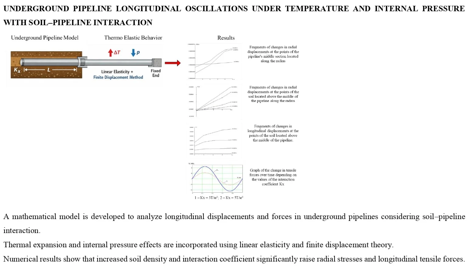
- A mathematical model is developed to analyze longitudinal displacements and forces in underground pipelines considering soil–pipeline interaction
- Thermal expansion and internal pressure effects are incorporated using linear elasticity and finite displacement theory
- Numerical results show that increased soil density and interaction coefficient significantly raise radial stresses and longitudinal tensile forces
1. Introduction
The transport is among the most significant elements of the economy of a state as the basis of industrial progress, trade and social integration. The transport system in a country is said to be similar to the blood vessels in a living body. This is analogical, as, similarly to the way blood supplies the cells of the body with the necessary nutrients, transport networks provide the uninterrupted flow of goods, resources, and people to facilitate economic prosperity and society well-being. In the transport infrastructure, railway culverts and railway bridges are very important in the continuous flow of trains and safety. Many reinforced concrete and steel water pipes (culverts), are in use on the railway lines in the world, and these are made to be a vital hydraulic structure that are used to manage the drainage and flow of water under embankments. The technical state of such structures has a direct impact on the safe movement of trains and the stability of the work of railroads in general. Most of these structures have however served several decades and as such, degradation of materials, greater intensity of loads and environmental effects (corrosion, erosion, and freeze thaw cycles) have been experienced. Research by Vasilyev and Konovalov has identified over 40 percent of reinforced concrete hydraulic structures in post-Soviet railway systems have dissimilar levels of decay, mostly because of inadequate waterproofing and concrete aging. Equally, according to the U.S. Federal Highway Administration and the European Railway Agency the bridges and culverts in the poor or fair condition are constantly rising under the impact of increased traffic volumes and the climatic factors. It is therefore important that these structures are maintained on time, inspected as regards to diagnostics, and rehabilitated. Prevention is done through repair of waterproofing membranes, sealing cracks, reinforcement corrosion proofing and structural strengthening to increase the service life and secure operation. According to the researchers like Kruglov and Anisimov, the operational reliability and durability of the water structures in the railway can be enhanced significantly by the use of modern waterproofing materials, fiber-reinforced polymer (FRP) systems, and modern monitoring technologies. Therefore, the technical state of railway culvert and other objects is not only a question of engineering safety but also economical benefit, security, and viability. The study of diagnostics, material science, and structural rehabilitation should continue so that these components of the transport system could be made serviceable in the long term.
2. Main part
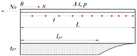
This article examines a straight-line underground section of a pipeline whose right end is stationary. For the generality of the solution, we will assume that the pipeline has a limited length .
As the initial parameter, we take the axial force , the remaining designations are shown in Fig. 1 [1-3].
Fig. 1Calculation scheme of the underground pipeline section
As the calculated model of the pipeline, we use a rod (beam) with a tubular cross-section interacting with the medium. The interaction of the pipeline with the soil is described by the dependence of the soil resistance on displacement, the diagram of which is shown in Fig. 2(a). It takes into account the limited nature of the reactions of the longitudinal connections. The analytical expression of the soil model presented in this diagram is as follows:
from this:
from this:
where: – ground resistance to longitudinal movement of the pipe; – proportionality coefficient, called the generalized coefficient of tangential resistance of the soil.
Depending on the loads, influences, and relative rigidity of the pipeline, it is possible that along the entire length of the considered section, the soil operates only in the elastic stage, characterized by condition Eqs. (1), or that two sections are located on this section, described by conditions Eqs. (1) and (2).
The section where the pipeline's interaction with the soil is described by the dependence Eq. (2), we will call it the limiting equilibrium section, and its length will be denoted by , in the future we will simply call it the first section [4].
The equilibrium equation of the element (see Fig. 2(b)) has the form:
Taking into account Eq. (1) and (2), for each of the sections, this equation is written as:
from this:
from this:
The thermo elasticity ratio, taking into account the two-axis stress state of the pressure pipeline, has the form:
where, is the longitudinal deformation; – material elasticity modulus; – cross-sectional area of the pipe walls; – linear expansion coefficient; – temperature difference, positive when heated; – Poisson's ratio, – annular stresses from internal pressure [4, 6].
In the linear formulation of the problem, deformation and displacement are related by the dependence:
Using Eq. (8) and assuming that the pipe cross-section, temperature drop, and internal pressure will be constant along the length, the equilibrium Eqs. (4) and (5) in displacements have the following form:
where:
Let's write the solution of Eqs. (9) and (10) with respect to displacements and forces:
We assume that the pipeline parameters are such that there is a section of limiting soil equilibrium along the pipeline length [5]. Then the boundary conditions and the conditions for the conjugation of both sections in this problem statement have the form:
From this: ,
From this:
From this , .
Based on these conditions, we determine the arbitrary constants - of Eqs. (12-15) and the length of the limiting equilibrium section:
The value of is determined by solving it relative to the transcendental equation :
Fig. 2Calculated soil model and pipeline element
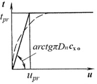
a)
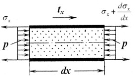
b)
Here, the following dimensionless parameters are introduced:
where
Determining from Eq. (18) and using Eq. (17) we find arbitrary constants, which allow us to determine the displacement and longitudinal force of any section of the pipeline using Eqs. (12-15).
According to the developed algorithm and programs, a linear section of the pipeline with a length of 10 m was calculated for different laying depths. Cases where the seismic wave direction coincides with the central axis of the structure and the case where the seismic wave is directed perpendicular to the axis of the structure are considered. The nature of the distribution of radial, tangential, and axial stresses depending on the direction of the seismic wave relative to the structure’s axis has been determined [7].
A reinforced concrete structure with physical and mechanical properties is taken as the tunnel material: 0.25 Tsek2/m4; 4.2×10⁵ T/m4; 9.5×10⁵ T/m4; 0; 1.80 m; 2.80 m.
Loess with physical and mechanical characteristics is taken as the material of the soil: 0.10 Tsek2/m4; 3.61×10² T/m2; 5.41×10² T/m2; 40 sek-1.
3. Heavy dense loam
The calculation results are presented in the form of graphs in Figs. 3-6. Fig. 3 shows fragments of changes in the radial displacements of the pipeline's middle section. Fig. 4 shows fragments of changes in the radial displacements of the soil located above the middle section of the pipeline [8, 9].
Fig. 3Fragments of changes in radial displacements at the points of the pipeline’s middle section located along the radius
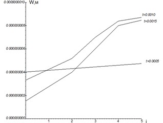
Fig. 4Fragments of changes in radial displacements at the points of the soil located above the middle of the pipeline along the radius
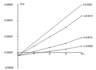
Fig. 5Fragments of changes in longitudinal displacements at the points of the soil located above the middle of the pipeline
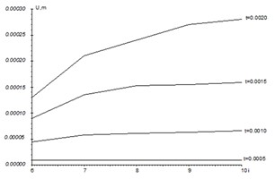
Fig. 6Changes in radial stresses of a point in the pipeline’s contact line with the soil, depending on the physical and mechanical properties of the soil. 1 – ρgr= 1.85 Т/m2; 2 – ρgr= 1.65 Т/m2
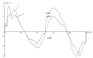
Fig. 5 shows fragments of changes in the longitudinal displacements of the soil points located above the pipe’s middle section [8-11]. Fig. 6 shows the changes in radial stresses at the point of contact of the pipeline with the soil, depending on the physical and mechanical properties of the soil.
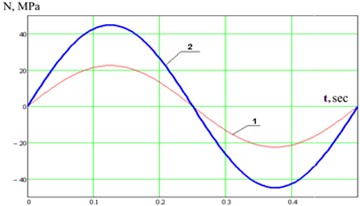
Fig. 7 shows the graphs of the change in tensile forces depending on the values of the interaction coefficient .
Fig. 7Graph of the change in tensile forces over time depending on the values of the interaction coefficient Kx. 1 – Kx= 3 Т/m3; 2 – Kx= 5 Т/m3
4. Conclusion
The conducted numerical analysis showed that the values of radial stresses at the points of contact of the pipeline with the soil increase proportionally to the increase in the density of the surrounding soil mass. This is due to the increase in resistance from the ground during pipeline deformation, which increases the contact pressure on its outer surface. Furthermore, it has been established that with an increase in the longitudinal interaction coefficient , modeling the relationship between the pipeline and the soil in the longitudinal direction, an increase in longitudinal tensile forces in the pipeline body is observed [7, 12]. This indicates that the increased interaction between the pipeline and the base leads to a redistribution of internal forces, increasing the level of stressed state. The obtained results allow us to conclude that it is necessary to take into account the soil density and interaction coefficient when designing underground pipelines, especially under complex soil conditions and variable loads.
5. Future scope
The conducted study provides a fundamental basis for further investigations into the mechanical behavior of underground pipelines under complex boundary and loading conditions. In future work, the effects of non-uniform temperature gradients, which may arise due to seasonal or operational fluctuations, can be incorporated into the model to enhance the accuracy of stress-strain predictions.
A promising area for development is the integration of non-linear elasticity and plastic deformation models, especially under high-pressure and elevated temperature conditions. Such refinement would allow capturing the actual behavior of materials that go beyond the assumptions of linear elasticity and contribute to more robust structural evaluations.
Another research should also be aimed at the introduction of viscoelastic or creep properties into the pipeline material under the long-term work under constant pressure. This will enable simulation of deformation processes to longer durations and have improved lifecycle estimates.
The modelling in terms of numbers can be improved with the Finite Element Method (FEM) due to 2D and 3D models that better depict the interaction of the pipeline and heterogeneous layers of soil with the impact of soil stratification, its moisture content, and any seismic effect.
It is suggested that the numerical results can be validated in the field by installing strain gauges and pressure sensors on already existing underground pipelines. This will verify the assumptions in modeling since data will be real-time collected over a number of years and enable the theoretical models to be verified through empirical data.
In the future cross disciplinary work with geotechnical engineers and material scientists may allow to devise customized composite materials or smart materials in pipelines. They may become able to react to external loading, more corrosion resistant, or able to have embedded sensors to self-monitor and predict when they will be damaged.
References
-
A. B. Aynbinder and A. G. Kamerstein, Calculation of Main Pipelines for Strength and Stability. Reference Guide. Moscow: Nedra, 1982.
-
P. P. Borodavkin, Soil Mechanics in Pipeline Construction: Textbook for Universities. Moscow: Nedra, 1986.
-
P. P. Borodavkin, Underground Pipelines. Moscow: Nedra.
-
U. Raxmanov, “Calculation of the interacting “soil-structure” system for seismic forces,” Bulletin of TashIIT, pp. 57–60, 2019.
-
U. Rakhmanov and G. Ismailova, “The main provisions of the methods of calculation of reinforced concrete structures,” The 3rd International Scientific Conference Construction Mechanics, Hydraulics and Water Resources Engineering (CONMECHYDRO 2021 AS), Vol. 2612, p. 060038, Jan. 2023, https://doi.org/10.1063/5.0135552
-
S. S. Salixanov, F. Z. Zokirov, Y. T. Xakimova, and G. B. Ismailova, “The effect of increasing loads on foundations of operating bridges,” in E3S Web of Conferences, Vol. 401, p. 01080, Jul. 2023, https://doi.org/10.1051/e3sconf/202340101080
-
C. Raupov, A. Karimova, F. Zokirov, and Y. Khakimova, “Experimental and theoretical assessment of the long-term strength of lightweight concrete and its components under compression and tension, taking into account the macrostructure of the material,” in E3S Web of Conferences, Vol. 264, p. 02024, Jun. 2021, https://doi.org/10.1051/e3sconf/202126402024
-
C. Raupov and G. Malikov, “Comparison of micro crack formation boundaries determined by complex of physical methods with long-term strength of expanded clay concrete under different types of stress state,” in E3S Web of Conferences, Vol. 365, p. 02023, 2023.
-
S. T. Djabbarov and R. H. Mukarramov, “Monitoring and forecasting of hazardous geological processes using a 3D scanning system,” in Asia-Pacific Conference on Applied Mathematics and Statistics, Vol. 2471, p. 030014, Jan. 2022, https://doi.org/10.1063/5.0089561
-
S. Salikhanov and F. Zokirov, “Studying possibilities of joint operation of main beam and protective layer constructions,” in the 3rd International Symposium on Civil, Environmental, and Infrastructure Engineering (ISCEIE), Vol. 3317, p. 030029, Jan. 2025, https://doi.org/10.1063/5.0266815
-
A. Khakimov, G. Kutumova, and Z. Mirzaeva, “Current trends in the development of automation surveying support in the construction of subways,” in E3S Web of Conferences, Vol. 168, No. 153, May 2020, https://doi.org/10.1051/e3sconf/202016800010
-
M. Z. Mahamadazizovna and R. M. Mahamadaminovich, “Mathematical modeling of calculation of spatial structures under variable loads,” JournalNX, Vol. 7, No. 5, pp. 246–249, 2021.
About this article

The authors have not disclosed any funding.
The datasets generated during and/or analyzed during the current study are available from the corresponding author on reasonable request.
Dr. Fakhriddin Zokirov is a scientific committee member of the 76th International Conference on Vibroengineering and was not involved in the editorial review and/or the decision to publish this article.
