Abstract
Impact from falling objects can easily cause the local deformation of pipeline, which threatens the safe and stable operation of pipeline. In order to study the dynamic response behavior of impacted buried pipelines in cold regions, the buried pipelines, frozen soil and falling objects are taken as the object. Considering the nonlinearity of pipeline material, the contact nonlinearity between pipeline, falling objects and frozen soil, a double nonlinear dynamic analysis model of buried pipeline in cold regions is established by explicit dynamic analysis method. The rationality of the model method is verified by comparing the curves in this paper with those from the experiment. Furthermore, the changing laws of dynamic response of pipeline influenced by different factors are discussed. The results show that: when the buried depth of pipeline is 2 m, the deformation and residual stress of pipeline increase with the increase of pipeline’s diameter-to-thickness ratio, the impact velocity of falling object and the water content of frozen soil, and the impact velocity of falling objects influences the dynamic response behavior of pipelines most significantly, followed by the diameter-thickness ratio of pipelines and the water content of frozen soil; When the diameter-thickness ratio of the pipeline is 58, the deformation and residual stress of pipeline decrease with the increase of buried depth by 75 % and 88 % respectively. Among the four influencing factors, when the impact velocity of falling objects is 10 m/s and the buried depth of pipeline is 3 m, the deformation amplitude of pipelines caused by falling objects is the smallest. It is suggested that in the high-risk regions of falling objects, the diameter-thickness ratio, buried depth and the water content of frozen soil can be reasonably controlled under the condition of predicting the maximum potential impact velocity of falling objects, so as to improve the ability of the pipeline to resist external impact damage, which provides theoretical basis and quantitative control standards for the impact design of pipeline engineering in cold regions.
Highlights
- Aiming at the problem of pipelines in cold regions being impacted by falling objects, we take buried pipelines, frozen soil and falling objects in cold regions as the research objects, and consider the force characteristics of the research objects to establish their mechanical models for analysis.
- Considering the material and contact nonlinearities of soil-pipeline systems in cold regions, a three-dimensional dual-nonlinear dynamic model for falling object impacts on buried pipelines was established using nonlinear dynamics analysis.
- Four types of influencing factors, namely pipeline burial depth, pipeline diameter-to-thickness ratio, impact velocity of falling objects and moisture content of frozen soil, were studied for the impact of falling objects on buried pipelines in cold regions.
1. Introduction
China is the third largest country in frozen soil area, and the national oil and gas pipeline network will inevitably cross the permafrost region [1]. As the “lifeline of the national economy,” oil and gas pipelines, once they fail, can lead to extremely severe consequences. Among many factors that lead to pipeline failures, external forces are crucial. According to incomplete statistics, accidents caused by external force damage account for up to 48.4 % of pipeline failures [2]. As one of the forms of external damage, the impact of falling objects easily causes local depression and deformation of the pipeline. It is of great practical significance to study the dynamic response behaviors of buried pipelines in cold regions under the impact of falling objects, so as to fully grasp the mechanical state of pipelines in cold regions and ensure the safe and stable operation of pipelines.
At present, experts and scholars at home and abroad have carried out relevant research work on the influence of falling objects on pipelines, and have achieved certain results. Zhou Yutong [3] took buried pipelines with internal corrosion defects as the research object, and analyzed the dynamic response of pipelines under different corrosion forms and corrosion parameters under the impact of falling rocks. Based on elastoplastic mechanics theory, Cui Yi et al. [4] studied the influence of different factors on the stress of buried pipelines under the action of rock collapse by using the finite element method. Li Qiaozhen et al. [5] used the numerical analysis method to carry out the dynamic analysis of buried pipelines under the impact of falling objects, and discussed the dynamic response variation law of pipelines under different influencing factors. Tian J. [6], Dong F. [7] et al. analyzed the strain law of buried pipelines under impact load by means of theoretical results, experimental results and finite element analysis. Teng Zhenchao et al. [8] carried out indoor tests on buried pipelines in frozen soil areas, and analyzed the strain variation law of pipelines by changing the shape and height of falling objects. Wang Hongbo et al. [9] proposed a method for calculating the maximum strain of buried pipelines under impact load, and obtained the critical circumferential buckling stress of pipelines through theoretical analysis. Peng Jian et al. [10] analyzed the influence of different factors on pipeline deformation during pipe-to-pipe collision by combining numerical simulation with experiment. Gu Ruijie et al. [11] predicted the maximum deflection of plastic deformation of high-energy pipeline under impact load based on the membrane force factor method (MFM), and verified its accuracy by comparing with numerical simulation results and experimental results. Yang Zhenglong et al. [12] analyzed the local buckling characteristics of deep-sea pipelines under the combined action of external hydrostatic pressure and impact loads based on the explicit dynamics method, and verified the rationality of the model approach through full-scale experimental results. Li Yuanbo et al. [13] carried out the force analysis of buried oil and gas pipelines under impact load and proposed the calculation method of pipeline stress and deformation. Xiong Jian et al. [14] established a calculation model of the buried pipeline impacted by rock collapse, and obtained the stress change curve and empirical formula. Zhang J. [15], Wang Y. [16] et al. took the buried pipeline as the research object, and studied the stress and deformation of the pipeline under the impact of falling rocks by using the numerical analysis method. Rao P et al. [17] took the buried pipeline as the research object and analyzed the stress and deformation of the buried pipeline under rock fall by using the two-stage method. Shao B et al. [18] took the exposed pipeline as the research object and studied the impact of factors such as impact velocity, rock fall size and impact direction on the dynamic response of the pipeline. Jiang F et al. [19, 20] used the finite element method combined with experiments to analyze the dynamic response of falling objects impacting pipelines under different seabed conditions.
To sum up, with existing research on the impact of falling objects mostly targeting pipelines in non-cold regions, there are few studies on the impact of falling objects on pipelines in cold regions. Most of the research [21-25] focuses on the frost heave of pipelines in cold regions, studies [26, 27] deal with the melting and sinking of the pipe trench, and research [28] explores how reverse faults cause buckling. Pipelines in cold regions may also face the threat of falling objects, and the properties of the impact medium of falling objects in cold regions and non-cold regions are different. Considering that pipeline integrity management covers the whole life cycle of a pipeline, during the construction stage, the pipeline is more likely to be partially deformed, especially under the influence of falling objects. In view of this, this paper focuses on the large diameter buried oil and gas pipeline during its construction period in cold regions, and analyzes the impact dynamics of falling objects on it. The variation laws of pipeline dynamic response behaviors with different influencing factors are discussed, and the related analysis results and methods can provide reference and guidance for pipeline integrity management in cold regions.
2. Physical model
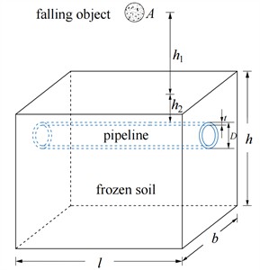
In this paper, buried oil and gas pipelines in flat cold regions are taken as the research object, and the dynamic responses under the impact of spherical falling objects are analyzed. The soil is a semi-infinite region, which needs to be simplified in the calculation process. It is assumed that the spherical falling object will neither deform nor break, nor will it rotate around its center of mass.
The diameter of the pipeline, the height of the falling object, and the buried depth of the pipeline are set to , , and respectively. The simplified frozen-soil area has a length of , a width of , and a height of . The Schematic diagram of the buried pipeline in the flat area of falling object impact is shown in Fig. 1. The whole impact process is analyzed by the dynamic display method, in which the Lagrange increment method is used to track the trajectory of a falling object.
It is assumed that a falling object with a weight of at the initial time falls freely from point at the height of from the ground, and the space position of point is marked as . When the falling rock moves downward and impacts the foundation, its motion trajectory equation is described by Eq. (1):
where, stands for the initial position of the falling object. When the falling object freely falls towards the surface, it undergoes a constant-acceleration motion during the process, and its velocity reaches the maximum when it hits the surface.
Fig. 1Schematic diagram of buried pipeline in flat area of falling object impact
a) Initial fall of the object

b) The falling object reaches its lowest point
When the falling object reaches the surface, it continues to move downwards due to the action of inertia. Due to the elastic-plastic properties of foundation and pipeline, the falling object decelerates because of the reaction force exerted by foundation and pipeline. When the falling object finally changes from the surface position to the position (as shown in Fig. 1(b)), the whole impact process satisfies the energy conservation equation:
were, (in J) is the kinetic energy of falling rocks when the maximum vertical displacement of the foundation occurs; (in J) is the kinetic energy of the object at the initial time; is the sum of work done by external forces, which include the gravity of falling object, with the corresponding work being (in J), and the force exerted by the foundation and the pipeline on the falling object , with the corresponding work being (in J).
Among them, the work done by gravity of falling objects can be expressed as:
The work done by the force exerted by the foundation and the pipeline on the falling object can be expressed as:
where, is a function of with the unit of N/m. The variable is related to the elastic modulus of the frozen soil foundation and of the pipeline; is composed of the frozen soil foundation deformation and the pipeline deformation , that is: , (in m).
After substituting Eq. (3) and Eq. (4) into Eq. (2), it can be further written as:
By further solving Eq. (5), we can obtain:
When the falling object falls to a certain point, according to the conservation of energy equation, it can be regarded that the velocity of the falling object is known, and the boundary conditions are:
When the falling object reaches the point maximum vertical displacement of the foundation at time t2, the boundary conditions are:
From the above analysis, it can be seen that in the process of falling objects impacting buried pipelines, falling objects transfer energy to the foundation through the contact point, and the force extends to the inside through the node of the foundation, and finally acts on the pipeline, causing local sag deformation of the pipeline.
3. Material model
3.1. Frozen soil material model
In traditional analysis, the Mohr-Coulomb (M-C criterion for short) yield criterion is used. Since the yield surface shape is hexagonal pyramidal and not suitable for numerical calculation, the Drucker-Prager (D-P criterion for short) yield criterion is often used for approximation. However, when the internal friction angle is greater than 30°, the effect of Drucker-Prager model approximating to Mohr-Coulomb model is not good. In order to improve the calculation accuracy, the parameter conversion of D-P yield criterion matching M-C yield criterion should be realized [29].
Given that cohesion and internal friction angle are the actual material parameters of the frozen soil, the position of the yield surface (named DP3) [30, 31] matches the M-C yield criterion and is calculated according to its yield criterion. The calculation formulas for material constants and are shown in Eq. (11):
The cohesion and the internal friction angle are set as the material constants of DP3. When the radius of the Mises circle in the -plane is equal to the radius of the circumscribed circle of the M-C yield criterion, there is:
Let , , the calculation formula of the modified frozen soil material parameters and are shown in Eq. (13):
3.2. Pipeline material model
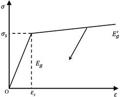
The pipeline adopts a linear hardening elastic-plastic model (as shown in Fig. 2), and its stress-strain relationship can be written as:
where, (in MPa) is the yield strength of pipeline steel; (in MPa) is the shear modulus of the pipeline steel, the meanings of other variable symbols are the same as before.
Fig. 2Linear hardening elastoplastic model
3.3. Falling material model
Because the spherical falling object neither deforms nor breaks during the falling process, and does not rotate around its center of mass, the rigid body material model is adopted.
4. Dynamic analysis
4.1. Basic parameters
The size of a buried oil and gas pipeline in the cold regions is 1016 mm×17.5 mm, the buried depth is 2 m, and a spherical falling object with a radius of 0.9 m falls freely from a height of 11.25 m to impact the buried pipeline. In order to study the dynamic response behavior of buried pipelines impacted by falling objects, a three-dimensional double-nonlinear dynamic response analysis model of buried pipelines under impact in cold regions is established by considering the contact nonlinear characteristics of spherical falling objects with frozen soil and oil and gas pipelines, as well as the material nonlinear characteristics of frozen soil and pipelines respectively. Frozen soil material parameters, pipeline material parameters [32] and falling material parameters are shown in Table 1-3.
Table 1Frozen soil material parameters
Density / kg·m-3 | Poisson’s ratio | Modulus of elasticity / MPa | Angle of internal friction / ° | Cohesion / kPa | Moisture content / % |
1900 | 0.3 | 30 | 38.1 | 87.3 | 30 |
Table 2Pipeline material parameters
Density / kg·m-3 | Poisson’s ratio | Modulus of elasticity / MPa | Shear modulus / MPa | Yield strength / MPa |
7900 | 0.3 | 210000 | 13500 | 480 |
Table 3Falling material parameters
Density / kg·m-3 | Poisson’s ratio | Modulus of elasticity / MPa |
2500 | 0.22 | 22500 |
4.2. Modeling method verification
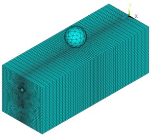
For the problem of buried pipelines in cold regions affected by falling objects, the rationality of model and method is the key point. According to the data in literature [8], considering the nonlinear contact characteristics between soil, falling object and pipeline, a grid model of buried pipeline in the cold regions is established by using solid elements, as shown in Fig. 3. Except that the top surface is a free boundary, the other five surfaces are set as non-reflective boundaries. By carrying out nonlinear dynamic analysis, points located at the 12 o’clock, 3 o’clock, and 6 o’clock positions around the circumference of the pipeline (in Fig. 4) were selected to draw the curves of axial and circumferential strain changing with time, as shown in Fig. 5.
Fig. 3Grid diagram of buried pipeline in the cold regions affected by falling object
a) Grid diagram of the whole structure
b) Grid diagram of the pipeline
Fig. 4Selection of strain points in different clock directions of the pipeline
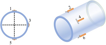
Fig. 5Curves of axial and circumferential strains of the pipeline changing with time
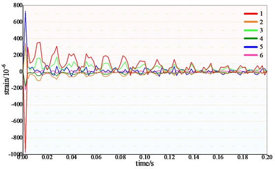
a) Curves of pipeline strain when falling object height is 2 m
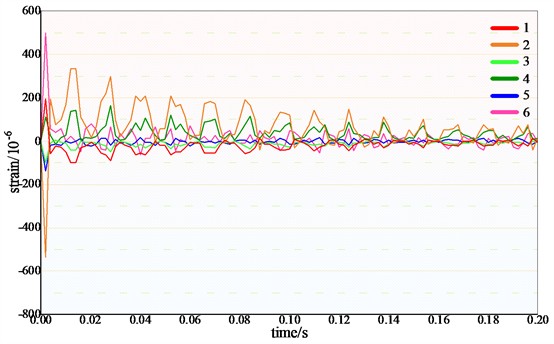
b) Curves of pipeline strain when falling object height is 1 m
As can be seen from Figs. 4-5, the strain at the top of the pipe is the maximum at the moment of the falling object impact, and then the strain decays until it tends to be stable. The top of the pipeline is compressed, the bottom is stretched, and the upper and lower strains of the pipeline are approximately anti-symmetric. These change laws and trends are basically consistent with the change laws and trends of experimental data in the literature, which verifies the rationality of the numerical model method in this paper.
4.3. Establishment of finite element model and dynamic analysis
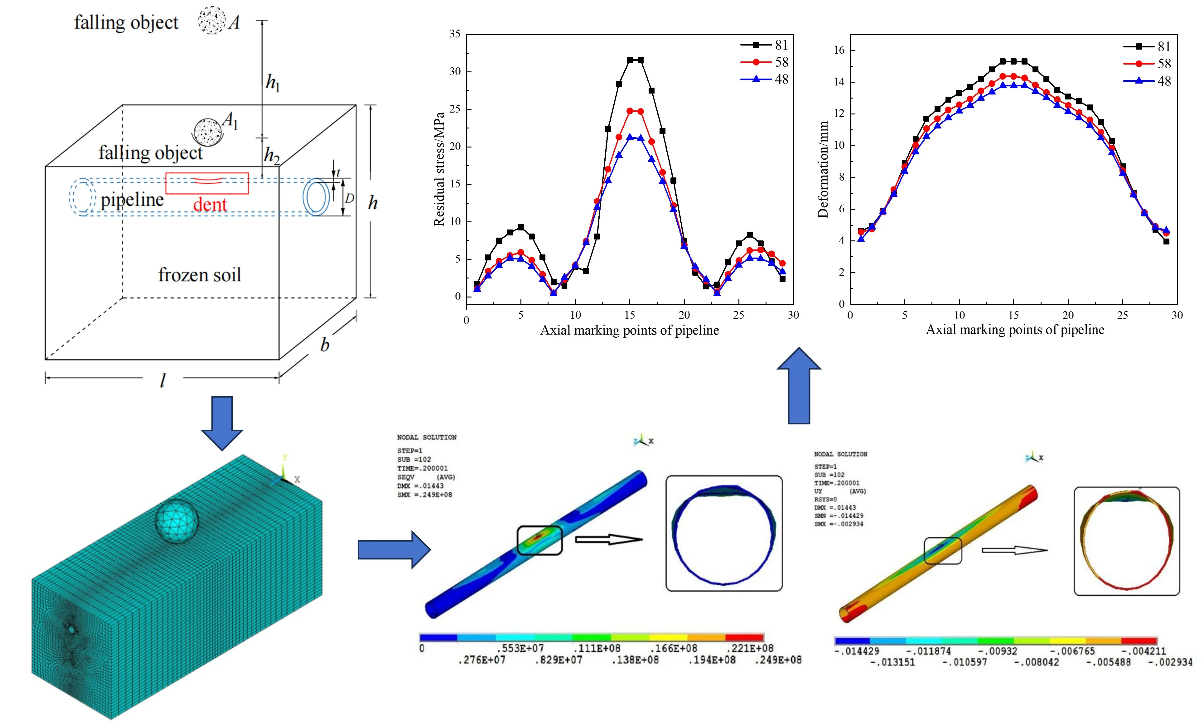
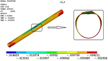
Based on the simplified model in Fig. 1, according to the shape characteristics of the falling object, soil mass and pipeline, the debris is discretized by using 10-node tetrahedron elements, while the soil and pipeline are discretized by using 8-node hexahedron elements. During the construction period, there is no internal pressure in the pipeline. The top impacted surface of the frozen soil is a free boundary, while the other surfaces are treated as non-reflecting boundaries. Through the nonlinear dynamic analysis, the cloud diagrams of the pipeline's residual stress and deformation are shown in Figs. 6-7 respectively.
From Figs. 6-7, it can be seen that when falling objects impact the buried pipeline at a speed of 15 m/s, the maximum residual stress of the pipeline is 24.9 MPa, which is located at the top of the pipeline directly below the impact of falling objects. The deformation of the pipeline is depression deformation, and the maximum value is 14.4 mm.
Fig. 6Cloud diagram of the pipeline’s residual stress
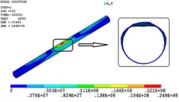
Fig. 7Cloud diagram of the pipeline’s deformation
4.4. Analysis of influencing factors of dynamic response
According to the analysis of the physical model, the factors that affect the dynamic response of the pipeline include: the buried depth of the pipeline, the impact velocity of falling object, and the elastic modulus of frozen soil. In addition, the resistance to impact deformation of pipelines with different diameter thickness ratio is also different.
In order to explore the dynamic response of the pipeline under different influencing factors, nonlinear dynamic analysis is conducted by changing the diameter-thickness ratio of the pipeline, the buried depth of the pipeline, the impact velocity of falling objects, and the water content of frozen soil.
4.5. Diameter-thickness ratio of the pipelines
According to the relevant requirements of GB 5021 and GB 50253, for buried pipelines impacted by falling objects, in addition to meeting the requirements of strength and stiffness, their stability should also be checked. Moreover, the selection of wall thickness should be guided by the critical buckling pressure of pipelines, and the critical diameter-thickness ratio to avoid pipeline buckling should be further determined.
The relevant calculation formulas of falling object mass , equivalent impact force , diffusion depth , equivalent pressure , critical buckling pressure and pipeline wall thickness are shown in Eqs. (15-20) respectively:
where, (in kg) is the falling mass, (in m) is the falling object radius, (in N) is equivalent impact force, (in m/s) is the falling velocity, (in s) is equivalent time, (in m) is the diffusion width, (in m) is diffusion depth, (in °) is the diffusion angle, (in MPa) is equivalent pressure, is the safety factor, (in MPa) is the critical buckling pressure. The safety factor is 3, and the soil acts as a buffer, so the equivalent time is 0.2 s.
When a falling object with a radius of 0.9 m impacts a pipeline buried at 2 m depth with a velocity of 15 m/s, the diameter-to-thickness ratio () to prevent pipeline buckling must satisfy 86.1. Therefore, in this section, dynamic analysis is carried out on buried pipelines with a diameter of 1016 mm, wall thicknesses of 21 mm, 17.5 mm, and 12.5 mm, and diameter-to-thickness ratio () of 48, 58, and 81 under the impact of falling objects.
Under the conditions that the impact velocity, the buried depth, and the water content of frozen soil are constant, the nonlinear dynamic analysis is carried out when the pipeline has diameter-thickness ratios of 48, 58 and 81 respectively. In order to facilitate the analysis of the rule, 29 marking points are successively taken on the top of the pipeline along the axial direction (Fig. 8), and the curves of the pipeline’s residual stress and deformation changing with the diameter-thickness ratio are shown in Figs. 9-10.
Fig. 8Axial marking points of pipeline
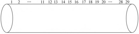
Fig. 9Curves of the pipeline's residual stress changing with the diameter-thickness ratio
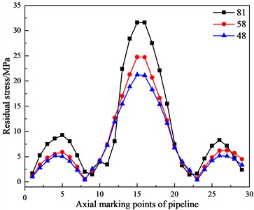
Fig. 10Curves of the pipeline's deformation changing with the diameter-thickness ratio
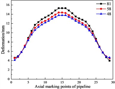
From Figs. 9-10, it can be observed that with the increase of the pipeline’s diameter-thickness ratio, its residual stress and deformation show an increasing trend. Specifically, the maximum residual stress increases from 21.1 MPa to 31.7 MPa, which is an increase of about 50 %. Additionally, after the impact, the maximum deformation at the top of the pipeline increases from 13.9 mm to 15.3 mm, which is an increase of about 10 %.
4.6. Buried depth of the pipelines
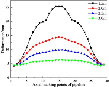
Under the conditions that the impact velocity, the diameter-thickness ratio, and the water content of frozen soil are constant, the nonlinear dynamic analysis is carried out when pipelines are buried at depths of 1.5 m, 2 m, 2.5 m and 3 m respectively. The curves of the pipeline's residual stress and deformation changing with the buried depth are shown in Figs. 11-12.
From Figs. 11-12, it can be observed that with the increase of the buried depth of the pipeline, the residual stress and deformation of the pipeline show a decreasing trend. Specifically, the maximum residual stress decreases from 49.6 MPa to 6.2 MPa, which is a decrease of about 88 %. Moreover, after the impact, the maximum deformation at the top of the pipeline decreases from 25.2 mm to 6.4 mm, which is a decrease of about 75 %, and the deformation caused by the impact of the falling object is the smallest when the buried depth is 3 m.
Fig. 11Curves of the pipeline’s residual stress changing with the buried depth
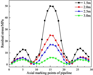
Fig. 12Curves of the pipeline’s deformation changing with the buried depth
4.7. Impact velocity of the falling object
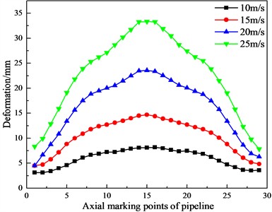
Under the conditions that the buried depth of the pipeline, the diameter-thickness ratio, and the water content of frozen soil are constant, the nonlinear dynamic analysis is carried out when the impact velocity is 10 m/s, 15 m/s, 20 m/s, and 25 m/s respectively. The curves of the pipeline’s residual stress and deformation changing with the impact velocity are shown in Figs. 13-14.
From Figs. 13-14, it can be observed that with the increase of the impact velocity of falling object, the residual stress and deformation of the pipeline show an increasing trend. Specifically, the maximum residual stress increases from 15.2 MPa to 58.8 MPa, which is an increase of about 2.9 times. After the impact, the maximum deformation at the top of the pipeline increases from 8.1 mm to 33.3 mm, which is an increase of about 3 times.
Fig. 13Curves of the pipeline’s residual stress changing with the impact velocity
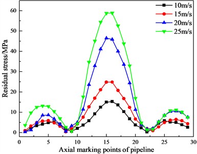
Fig. 14Curves of the pipeline’s deformation changing with the impact velocity
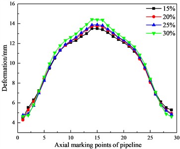
4.8. Water content of the frozen soil
The water content of frozen soil affects its shear strength. As the water content increases, its cohesion decreases [33]. In order to investigate the influence of frozen soil water content on the dynamic response of pipelines, under the conditions that the buried depth, the diameter-thickness ratio and the impact velocity are constant, the nonlinear dynamic analysis is carried out when the frozen soil water content is 15 %, 20%, 25 % and 30 % respectively. The curves of the pipeline’s residual stress and deformation changing with the water content of the frozen soil are shown in Figs. 15-16. Frozen soil material parameters with the different water content [34] are shown in Table 4.
From Figs. 15-16, it can be observed that with the increase of the frozen soil water content, the pipeline's residual stress and deformation increase. Specifically, the maximum residual stress increases from 19.4 MPa to 24.9 MPa, which is an increase of about 28 %. After the impact, the deformation at the top of the pipeline increases from 13.4 mm to 14.4 mm, which is an increase of about 7 %.
Table 4Frozen soil material parameters with the different water content
Moisture content / % | Angle of internal friction / ° | Cohesion / kPa |
15 | 46.3 | 128.7 |
20 | 41.7 | 115.2 |
25 | 39.99 | 108.8 |
30 | 38.1 | 87.3 |
Fig. 15Curves of the pipeline’s residual stress changing with the water content of the frozen soil
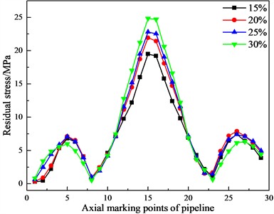
Fig. 16Curves of the pipeline’s deformation changing with the water content of the frozen soil
5. Conclusions
1) The verification of the three-dimensional nonlinear model of buried pipeline impacted by the falling object in the cold regions has been carried out, and the change laws and trends of axial and circumferential strains at the top, the side and the bottom of the pipeline are basically consistent with the change laws and trends of experimental data in literature [8], which verifies the rationality of the numerical model method in this paper.
2) For the buried pipelines with a depth of 2 m, the influencing factors of diameter-thickness ratio, impact velocity and frozen soil water content are analyzed. The results show that when the diameter-thickness ratio of the pipeline, the impact velocity of the falling object and the water content of the frozen soil increase, the pipeline’s deformation and residual stress also increase. When the impact velocity of the falling object is 10 m/s, the deformation amplitude caused by the impact of the falling object is at the minimum. For the pipeline with a diameter- thickness ratio of 58, the deformation of the pipeline caused by the impact of the falling object experiences the minimum change.
3) Under the condition that the buried depth of the pipeline is constant, the impact velocity of falling object has the greatest influence on the dynamic response behavior of the pipeline, followed by the diameter-thickness ratio of the pipeline and the frozen soil water content. With the increase of the buried depth, the pipeline's residual stress and deformation also decrease, which shows that covering the pipeline with soil can effectively reduce the harm of the impact load on the buried pipeline. In engineering practice, comprehensive consideration is given to factors such as the characteristics of the routing environment along the pipeline. Based on these, measures are taken to improve the pipeline’s resistance to external impacts and prevent damage, including properly adjusting the diameter-to-thickness ratio of the pipeline, the buried depth, and the water content of the frozen soil. These measures ensure the safe and stable operation of the pipelines in cold regions.
References
-
Q. Y. Li et al., “Current construction status and development trend of global oil and gas pipelines in 2020,” Oil and Gas Storage and Transportation, Vol. 40, No. 12, pp. 1330–1337, Dec. 2021.
-
C. H. Shen, Y. Li, and L. H. Fan, “China petroleum and chemical standard and quality,” China Petroleum and chemical standards and quality, Vol. 41, No. 9, pp. 44–45, Sep. 2021.
-
Y. T. Zhou, “Dynamic response analysis of buried pipelines containing corrosion under the impact of falling rocks,” Yangtze University, Wuhan, 2023.
-
Y. Cui and H. Q. Ma, “Stress variation law of buried collecting and transporting pipeline under rock collapse,” Lanzhou University of Technology Journal, Vol. 47, No. 2, pp. 60–64, Feb. 2021.
-
Q. Z. Li, M. Luo, Z. Q. Shi, J. Wang, and Q. Zhang, “Dynamic response behaviors of buried line pipes subjected to the impact of spherical falling objects,” Natural Gas Industry, Vol. 41, No. 12, pp. 136–143, Dec. 2021.
-
J.-P. Tian, J. Zhang, F.-F. Dong, and G.-F. Du, “Dynamic response of buried pipeline subject to impact loads using piezoceramic transducers,” International Journal of Pressure Vessels and Piping, Vol. 177, p. 103984, Nov. 2019, https://doi.org/10.1016/j.ijpvp.2019.103984
-
F. Dong, X. Bie, J. Tian, X. Xie, and G. Du, “Experimental and numerical study on the strain behavior of buried pipelines subjected to an impact load,” Applied Sciences, Vol. 9, No. 16, p. 3284, Aug. 2019, https://doi.org/10.3390/app9163284
-
Z. C. Teng, Y. X. Zhao, Y. C. Teng, X. Y. Liu, and J. Ji, “Experimental study on dynamic response of buried pipeline under impact load in frozen soil,” Earthquake Engineering and Engineering Vibration, Vol. 41, No. 6, pp. 168–176, 2019.
-
H. B. Wang, X. Z. Zhang, P. Wang, H. D. Wang, and L. R. Li, “Dynamic response analysis of buried pipeline in frozen soil area under impact load,” Petroleum engineering construction, Vol. 35, No. 5, pp. 1–5, 2009.
-
J. Peng, L. Liu, and Y. Y. Shi, “Numerical simulation of the high-energy piping impact process in a nuclear power plant,” Journal of Harbin Engineering University, Vol. 44, No. 2, pp. 307–313, 2023.
-
R. J. Gu, C. W. Dong, J. He, X. D. Sun, and D. Yao, “Maximum deflection prediction method for plastic large deformation of high-energy pipelines under impact load,” Nuclear Power Engineering, Vol. 46, No. 1, pp. 216–224, 2025.
-
Z. L. Yang, J. X. Yu, H. C. Chen, Y. Yu, and J. H. Duan, “Local buckling characteristics of deep-sea pipelines under impact loading,” Journal of Tianjin University, Vol. 52, No. 3, pp. 255–261, 2019.
-
Y. B. Li, J. H. Wang, and S. Luo, “Stress and deformation analysis of buried oil and gas pipeline under geological collapse impact,” China Storage and Transportation, No. 9, pp. 92–93, 2010.
-
J. Xiong, Q. L. Deng, H. L. Zhang, and W. J. Pang, “Safety evaluation of buried pipeline under impact load of rockfall,” Safety and Environmental Engineering, Vol. 20, No. 1, pp. 108–114, 2013.
-
J. Zhang, Z. Liang, C. Han, and H. Zhang, “Buckling behaviour analysis of a buried steel pipeline in rock stratum impacted by a rockfall,” Engineering Failure Analysis, Vol. 58, pp. 281–294, Dec. 2015, https://doi.org/10.1016/j.engfailanal.2015.09.009
-
Y. Wang, M. Xie, and C. Su, “Dynamic reliability evaluation of buried corroded pipeline under rockfall impact,” Eksploatacja i Niezawodność – Maintenance and Reliability, Vol. 24, No. 2, pp. 275–288, Jun. 2022, https://doi.org/10.17531/ein.2022.2.9
-
P. Rao, Z. Wu, and J. Cui, “Analysis of deformation of adjacent buried pipeline under rockfall impact load,” Geotechnical and Geological Engineering, Vol. 40, No. 3, pp. 1463–1474, Sep. 2021, https://doi.org/10.1007/s10706-021-01975-w
-
B. Shao, Y. Yan, X. Wang, and X. Yan, “Dynamics and strain-based design of the large-diameter pipe under the impact of a falling rock,” in IOP Conference Series: Materials Science and Engineering, Vol. 738, No. 1, p. 012010, Jan. 2020, https://doi.org/10.1088/1757-899x/738/1/012010
-
F. Jiang and S. Dong, “Two-level quantitative risk analysis of submarine pipelines from dropped objects considering pipe-soil interaction,” Ocean Engineering, Vol. 257, p. 111620, Aug. 2022, https://doi.org/10.1016/j.oceaneng.2022.111620
-
F. Jiang, S. Dong, Y. Zhao, Z. Xie, and C. Guedes Soares, “Investigation on the deformation response of submarine pipelines subjected to impact loads by dropped objects,” Ocean Engineering, Vol. 194, p. 106638, Dec. 2019, https://doi.org/10.1016/j.oceaneng.2019.106638
-
X. Li, Q. Wu, and H. Jin, “Mitigation strategies and measures for frost heave hazards of chilled gas pipeline in permafrost regions: A review,” Transportation Geotechnics, Vol. 36, p. 100786, Sep. 2022, https://doi.org/10.1016/j.trgeo.2022.100786
-
N. Yang, H. Zheng, H. Cai, Y. Liu, and S. Nishimura, “Study on multidimensional frost heave characteristics and thermal-hydro-mechanical predictive model,” Cold Regions Science and Technology, Vol. 224, p. 104227, Aug. 2024, https://doi.org/10.1016/j.coldregions.2024.104227
-
Q. Ma, G. Zeng, J. Zheng, and Y. Pan, “Laboratory investigation on the pipeline-soil interaction under different freezing conditions,” Cold Regions Science and Technology, Vol. 217, p. 104050, Jan. 2024, https://doi.org/10.1016/j.coldregions.2023.104050
-
H. Li, Y. Lai, and L. Li, “Impact of hydro-thermal behaviour around a buried pipeline in cold regions,” Cold Regions Science and Technology, Vol. 171, p. 102961, Mar. 2020, https://doi.org/10.1016/j.coldregions.2019.102961
-
Z. Ye, J. Lu, M. Zhang, W. Pei, and S. Li, “Experimental study on the movement of oil spill under freeze-thaw action,” Research in Cold and Arid Regions, Vol. 16, No. 3, pp. 111–120, Jun. 2024, https://doi.org/10.1016/j.rcar.2024.07.002
-
W. Wang, W. Y. Du, Y. G. Tang, W. Y. Xia, H. N. Liu, and Y. Lu, “Sensitivity of factors affecting freeze-thaw of pipeline foundation soil in permafrost region,” Oil and Gas Storage and Transportation, Vol. 39, No. 10, pp. 1155–1164, 2020.
-
Z. Chen et al., “Model test on cooling performance of a new method for mitigating permafrost thaw around buried oil pipeline,” Case Studies in Thermal Engineering, Vol. 59, p. 104581, Jul. 2024, https://doi.org/10.1016/j.csite.2024.104581
-
J. Xue, X. Wang, L. Ji, and X. Dong, “Performance of buried pipeline under reverse fault in permafrost region,” International Journal of Pressure Vessels and Piping, Vol. 207, p. 105119, Feb. 2024, https://doi.org/10.1016/j.ijpvp.2023.105119
-
Y. R. Zheng, “Recent advances in geomechanics-Generalized plastic mechanics,” Chinese Journal of Geotechnical Engineering, No. 1, pp. 1–10, 2003.
-
Y. R. Zheng and S. Y. Zhao, “Application of finite element strength reduction method in soil slope and rock slope,” Chinese Journal of Rock Mechanics and Engineering, No. 19, pp. 3381–3388, 2004.
-
C. G. Zhong and Z. Zhang, “Conversion of slope safety factor obtained by using different Drucker-Prager yield criteria,” Journal of Rock and Soil Mechanics, Vol. 32, No. 12, pp. 3751–3754, 2011.
-
A. L. Yao, S. P. Zhao, H. Q. Mo, X. G. Zeng, and Y. J. Liu, “Numerical analysis of impact response of underground explosion to buried gas pipeline,” Journal of Southwest Petroleum University (Natural Science Edition), Vol. 31, No. 4, pp. 168–172, 2009.
-
K. Huang, W. J. Wan, G. Chen, and Y. Zeng, “Experimental study on the relationship between shear strength and moisture content of unsaturated soil,” Rock and Soil Mechanics, Vol. 33, No. 9, pp. 2600–2604, 2009.
-
Y. X. Zhao, “Dynamic response analysis of buried pipeline under impact load in frozen soil area,” Northeast Petroleum University, Northeast Petroleum University, Daqing, 2021.
About this article

The research work is financially supported by the Daqing guiding science and technology plan project (No. zd-2023-33), the Heilongjiang Natural Science Foundation project (No. LH2021E011), the Heilongjiang Natural Science Foundation project (No. LH2022A003).
The datasets generated during and/or analyzed during the current study are available from the corresponding author on reasonable request.
Qiaozhen Li: Frame building, paper writing. Chao Wang: numerical analysis, data processing, paper writing. Peng Wang: model building. Min Luo: Frame building. Hao Wang: numerical analysis, data processing. Ye Lu: Frame building, model building.
The authors declare that they have no conflict of interest.
