Abstract
Through field measurement, numerical simulation and theoretical analysis, the influence of shield tunnel construction on the deformation of ceramic soil layer strip foundation is discussed. A three-dimensional numerical model of strip foundation in ceramic soil layer is established, and the effects of different shield types and parameters on the longitudinal deformation of strip foundation are analyzed using Timoshenko beam model. The increase of thrust of shield, torque of cutter head and speed of driving led to an increase of about 25 %, 28 % and 32 %, respectively, while the decrease of pressure of synchronous grouting and pressure of shield opening also aggravated the settlement. The study quantified the leading role of pressure of shield opening for the first time, revealed the double-sided effect of excavation pressure, and proposed a multi-parameter collaborative optimization strategy.
Highlights
- The influence of shield tunnel construction on foundation deformation was discussed
- A three-dimensional numerical model based on the strip was established
- The influence of longitudinal deformation of the strip foundation was analyzed
1. Introduction
With the wide application of shield tunnel in building crossing engineering, how to ensure stratum stability, control ground settlement and deformation, and reduce the impact on buildings has become an important topic in current research [1].
Shield tunnel construction involves complex processes such as excavation, pipe assembly and grouting behind the wall [2]. Many researchers have deeply discussed the influence of construction parameters (such as excavation speed and grouting pressure) on formation deformation [3] through numerical simulation, theoretical analysis and on-site monitoring [4]. For example, scholars put forward the concept of land subsidence tank and gave the formula for calculating the width of subsidence tank [5]. Subsequently, Peck formula was further modified to include factors such as excavation speed and grouting pressure, providing a theoretical basis for the control of geological deformation in shield construction [6]. When the shield tunnel passes through the building, the foundation of the building may be deformed such as settlement, inclination and even cracks [7]. Studies have shown that formation loss and insufficient grouting pressure are the main causes of building foundation settlement [8]. At the same time, the structural type of the building (such as frame structure, shear wall structure) and foundation form (such as strip foundation and pile foundation) will also have a significant impact on the deformation [9]. Through the method of combining numerical simulation and field monitoring, scholars have deeply studied the settlement law of building foundation, providing an important reference for deformation prediction and control [10]. In order to reduce the impact of shield tunnel construction on buildings, scholars at home and abroad put forward a series of risk control measures. These measures include optimizing shield construction parameters (such as tunneling speed and grouting pressure), strengthening grouting reinforcement, and setting up isolation piles or walls [11]. For example, optimization of tunneling speed and grouting pressure can effectively reduce formation losses and the influence of insufficient grouting pressure [12]. Grouting reinforcement and installation of seismic isolation piles before construction are conducive to improving the bearing capacity and stability of the strata, thereby reducing the impact of construction on buildings [13]. Although significant progress has been made in theoretical model, deformation mechanism and risk control of shield tunnel through buildings, there are still some deficiencies [14]. For example, the applicability of existing models under different geological conditions and construction environments needs to be verified, the depth of research on building deformation mechanism needs to be strengthened, and the economy and operability of risk control measures need to be further optimized [15]. Future studies should be combined with interdisciplinary methods to deepen the study of multi-parameter coupling, so as to provide more comprehensive theoretical support and technical guidance for engineering practice of shield tunnel crossing buildings [16].
Although many researchers have conducted extensive research on the impact of shield tunnel excavation on surface deformation and have achieved certain results, there are still some deficiencies in theoretical research and practical application, which are reflected in the following aspects: The universality of theoretical models is insufficient. Existing studies are mainly based on specific geological conditions and construction environment, and the theoretical models proposed (such as Peck formula and its modified formula) have certain limitations in practical application [17]. For example, the applicability of these models in complex geological conditions (such as soft soil, karst formations) or special construction environments (such as high-density urban areas) has not been fully verified [18]. In addition, construction parameters (such as excavation speed and grouting pressure) are considered only in the model, which fails to fully reflect the influence of multi-parameter coupling on formation deformation [19]. Studies on the diversity of geological conditions and construction environment are insufficient. The influence of shield tunnel construction on geological deformation is significantly influenced by geological conditions (such as soil properties and groundwater level) and construction environment (such as building density and traffic load) [20]. However, existing studies mostly focus on single geological conditions or idealized construction environment, and lack systematic studies on different geological conditions and complex construction environment [21]. For example, in shield construction in soft soil area and karst area, there may be significant differences in the mechanism and control measures of geological deformation, but relevant studies have not been deeply discussed [22]. The depth of the research on the deformation mechanism of buildings is insufficient. Although there have been studies on the deformation of buildings caused by shield tunnel passing through buildings (such as settlement, tilt and crack), the research on the deformation mechanism is still insufficient. For example, the interaction mechanism between building foundation forms (such as strip foundation, pile foundation) and shield construction parameters has not been fully defined [23]. In addition, the influence of building structure type (such as frame structure, shear wall structure) on deformation has not been fully quantified. In order to make up for the above shortcomings, future research can be carried out from the following aspects: Building a more universal theoretical model: combining the multi-parameter coupling [24], developing a theoretical model suitable for complex geological conditions and construction environment [25]. Deepen the research on building deformation mechanism: quantitatively analyze the interaction mechanism between building foundation form, structure type and shield construction parameters
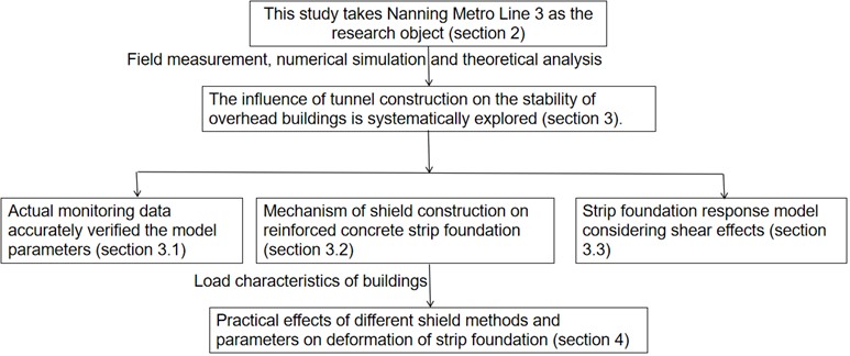
Taking Nanning Metro Line 3 as the research object (Section 2), this study systematically explores the influence of tunnel construction on the stability of overhead buildings through the combination of field measurement, numerical simulation and theoretical analysis. Firstly, a three-dimensional numerical model was constructed, and the actual monitoring data was used to accurately verify the model parameters to ensure the reliability of the model (Section 3.1). On this basis, the concrete action mechanism of shield construction on reinforced concrete bar foundation is further revealed through the in-depth analysis of formation deformation (Section 3.2). Combined with the simulation results of tunnel excavation on the strip foundation of superstructure and the load characteristics of the building, a response model of strip foundation considering shear effect was studied and established, providing a more accurate theoretical framework for the analysis of foundation deformation (Section 3.3). Finally, through model verification and simulation results, the research system evaluated the actual influence of different shield methods and parameters on the deformation of strip foundation (Section 4), as shown in Fig. 1. It provides scientific basis and practical guidance for the type selection and construction parameter optimization of shield machine in similar projects. This study not only deepens the understanding of the interaction between tunnel construction and building structure, but also provides an important reference for risk control and technical decision-making in engineering practice.
Fig. 1Main research contents
2. Construction site
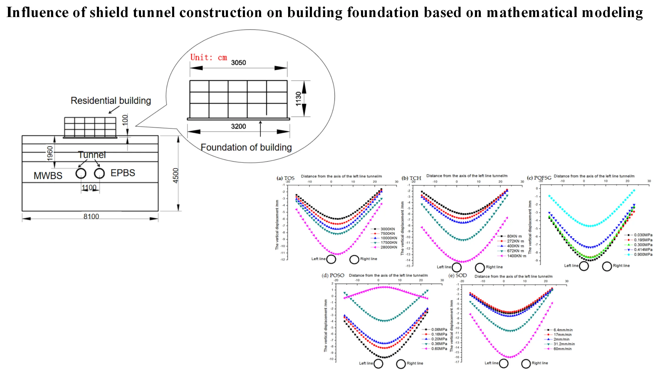
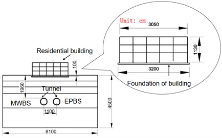
For the Nanning Metro Line 3 section between Donggelu and Binhulu stations, the shield tunneling method was chosen, spanning a total length of 957 meters. During the construction process, the tunnel needed to traverse through various geological layers, including gravel layers, silty clay layers, and partially silt and siltstone layers. The distance between the tunnel sections ranges from 8.0 to 14.0 meters. Table 1 provides detailed physical property parameters of these soil layers.
Fig. 2 shows the construction and shield tunnel layout, where the left side is first excavated with mud pressurized shield (MWBS), followed by the right side excavated with earth pressurized shield (EPBS). The cutting head diameter of both shield machines is 6280 mm. The tunnel section is 5.4 meters long and the ring is 1.5 meters wide. All of them are C50 strength concrete. In order to evaluate the excavation effect of MWBS and EPBS tunnels and compare with the field conditions, it is necessary to analyze the influence of the shield machine on the strata under three working conditions, as shown in Table 2 for details.
Table 1Physical parameters of soil layers of case 1 and case 2
Soil layer | Density/ (kg/m3) | Static lateral pressure coefficient | Modulus of elasticity / MPa | Cohesion / kPa | Internal friction angle / ° | Poisson’s ratio |
Gravel layer | 1.96 | 0.45 | 4.5 | 15 | 10 | 0.35 |
Ceramic soil layers | 1.98 | 0.38 | 6.5 | 38 | 13 | 0.33 |
Boulder layer | 2.06 | 0.3 | 18 | 0 | 35 | 0.3 |
Mudstone layer | 2.12 | 0.25 | 30 | 89 | 25 | 0.25 |
Table 2Numerical analysis condition
Type | Left line | Right line |
Real situation | The mud-water balance shield | The earth pressure balance shield |
Simulation situation 1 | The mud-water balance shield | The mud-water balance shield |
Simulation situation 2 | The earth pressure balance shield | The earth pressure balance shield |
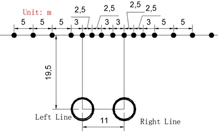
Fig. 2Diagram between buildings and shield tunnels
3. Reliability verification of theoretical calculation model
3.1. Analysis of measured data of surface
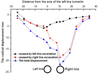
A 3D numerical model is constructed, and the parameters of the model are verified accurately by the actual monitoring data to ensure the reliability of the model. The ground settlement monitoring points are shown in Fig. 3. The displacement change of the settlement monitoring point was measured by a high-precision total station instrument, and the measured settlement curve of the soil above the tunnel was obtained, as shown in Fig. 4. The maximum settlement on the left side of the soil above the tunnel is 5.8 mm, and there is no significant settlement within 8 m of the soil above the tunnel. EPBS caused the maximum settlement of 18.6 mm on the right side of the soil above the tunnel, and the settlement was not obvious in the range of 18 m above the tunnel.
Fig. 3Layout of section monitoring points
a) Axial direction of tunnel
b) Transverse direction of tunnel
Fig. 4The measured settlement curve of DB26 section
3.2. Vertical displacement calculation of building strip foundation
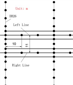
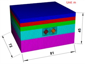
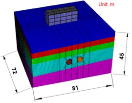
Based on the simulation results of tunnel excavation on superstructure bar foundation and the load characteristics of buildings, a response model of bar foundation considering shear effect is developed, which provides a more accurate theoretical framework for the analysis of foundation deformation. The model is based on actual geological conditions, with a tunnel burial depth of 19.5 meters and a spacing of 11 meters between two parallel tunnels. The model dimensions are 72 m×81 m×45 m. The three-dimensional numerical model is shown in Fig. 5. The numerical simulation software FLAC3D was used to conduct numerical simulation research. In this paper, Mohr-coulomb elastoplastic model was adopted for soil, elastic materials were used for shield shell, lining segment and grouting layer, and formation material parameters were calculated using survey data. The boundary conditions were non-reflective boundaries, and the mesh size ranged from 2mm to 10cm. The mesh is divided according to the degree of precision, and the accuracy of the finite element model verification is studied by trial and error method, and the nonlinear combination of geometry and material is carried out. According to the field monitoring data, the accuracy of the finite element model verification is guaranteed.
Fig. 5Three-dimensional numerical model
a) No buildings
b) Existing buildings
Fig. 6Influence model of tunnel excavation on strip foundation
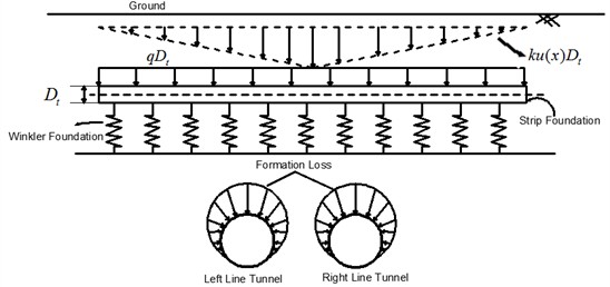
The analysis of tunnel force is simplified and the displacement equation of foundation pit excavation is obtained. The factors such as shear force and bending moment are mainly considered, while the axial force is ignored. Fig. 6 shows the influence model of tunnel excavation on strip foundation. Fig. 7 shows this simplified model.
Fig. 7Force analysis of microelement
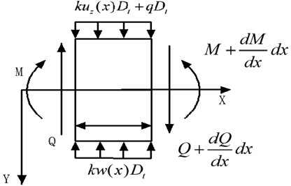
The stress of any trace element in Fig. 7 is analyzed, and the deformation equation of strip foundation under the action of of free soil settlement [21] is obtained:
The equation is defined as follows: and are the additional shear force and bending moment of the bar foundation respectively (see Fig. 7 for directions), is the reaction coefficient, is the width of the foundation, and is the equivalent body weight of the building. According to Timoshenko beam theory, and of a bar foundation are related to vertical displacement and rotation Angle [22]:
Eq. (5) and Eq. (6) give Eq. (7):
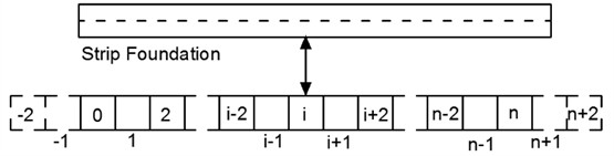
Eq. (7) reveals the longitudinal deformation of strip foundation under tunnel excavation. Because the equation is a fourth-order ordinary differential equation, the solution is complicated, so the finite difference method is used to simplify the calculation. Divide the bar base into nodes and add two virtual nodes at each end with a spacing of 1 (see Fig. 8). According to the finite difference principle, the differential Eq. (7) is transformed into the difference form:
where, ,,, and are respectively the vertical displacements of node elements. By analogy, Eq. (6) is deduced to obtain Eq. (9):
Fig. 8Discrete sketch of strip foundation of existing buildings
Eq. (10) can be obtained by Eqs. (9) and (4):
Eq. (11) is obtained by deriving Eq. (5):
Eq. (12) is obtained by combining Eq. (5) and Eq. (11):
The following equation can be obtained by combining the above equation:
The matrix form of building strip foundation displacement is obtained as follows:
where:
Let , , then Eq. (19) can be written as :
By analyzing the expression of vertical displacement of building strip foundation, it can be seen that the reaction coefficient of foundation bed, equivalent flexural stiffness of building strip foundation and equivalent shear stiffness of building strip foundation are very important parameters.
3.3. Verification of theoretical model
The computational results were compared with field monitoring data and numerical simulation data (see Fig. 5(b)), as shown in Fig. 9. The results demonstrated a high degree of agreement between the simulations and the actual measurements. However, due to the limitations of the simplified conditions, the Timoshenko beam theory did not fully capture the longitudinal deformation of the foundation in the simulation, leading to a slightly narrower predicted settlement curve.
Table 3Theoretical calculation parameter table
Parameter | Shear stiffness / (N·m2) | Flexural rigidity / (N·m2) | Foundation coefficient / (N/m3) |
Numerical value | 1.5e10 | 2e9 | 4199e3 |
Fig. 9The comparison of each working condition

4. Deformation analysis of buildings
4.1. Orthogonal experimental analysis - case 1
Through model verification and simulation results, the actual influence of different shield methods and parameters on the deformation of strip foundation is systematically evaluated. Orthogonal experimental analysis is an efficient multi-factor experiment design method. By choosing orthogonal table to arrange the experiment, the influence of multiple factors and their interaction on the results can be comprehensively investigated with less experiment times. The core idea is to use the balanced dispersion and neat comparability of orthogonal tables to ensure that the combination of each factor level is representative. Orthogonal experimental analysis is widely used in engineering, manufacturing, scientific research and other fields, which can significantly improve the test efficiency, reduce the cost, and provide scientific basis for optimizing the parameter combination. Through an orthogonal test table (Table 4), different excavation parameters were set to obtain data under these parameters, as shown in Fig. 10.
Table 4Analysis table
Influence factor | k1 | k2 | k3 | k4 | K5 |
Thrust of shield (TOS) / kN | 3000 | 7500 | 10000 | 17500 | 28000 |
Torque of cutter head (TCH) / (kN·m) | 80 | 272 | 400 | 672 | 1400 |
Pressure of synchronous grouting (POFSG) / MPa | 0.03 | 0.195 | 0.3 | 0.414 | 0.9 |
Pressure of shield opening (POSO) / MPa | 0.06 | 0.16 | 0.2 | 0.36 | 0.6 |
Speed of driving (SOD) / (mm/min) | 6.4 | 17 | 20 | 31.2 | 60 |
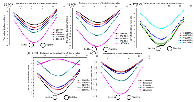
Furthermore, TCH, and SOD increased, also increased accordingly, and the increase was positively correlated with the thrust value. Additionally, a decrease in the POFSG and POSO also led to an increase in the maximum settlement value, where a higher POSO could even cause uplift deformation of the ground surface.In addition, the study also found that TCH and SOD showed a significant increase trend during tunnel construction, and the increase amplitude was positively correlated with the construction thrust value. For example, TCH increases from 80 knm to 1400 knm, the sedimentation two decreases from 0 to –15 mm, SOD increases from 6.4 mm/min to 60 mm/min, and the sedimentation amount decreases from 0 to –17 mmm. This phenomenon shows that with the increase of shield thrust, the deformation degree of tunnel surrounding rock and surface also increases, revealing the direct influence of thrust parameters on formation stability. At the same time, the decrease of POFSG and POSO will also lead to the significant increase of the maximum surface settlement value, and the increase of POSO may even lead to the uplift and deformation of the surface. This finding shows that the control of the propulsion pressure and velocity of shield tunneling machine has an important effect on the surface deformation mode: when the propulsion pressure is insufficient or the propulsion speed is too fast, the formation stress is not released sufficiently, which may lead to the intensification of settlement; However, when the advancing speed is too fast, the redistribution of formation stress may lead to local uplift. These results further emphasize the importance of optimization of shield construction parameters and provide scientific basis for controlling surface deformation and ensuring construction safety in engineering practice.
Fig. 10Deformation analysis of building strip foundation
4.2. Range analysis – Case 1
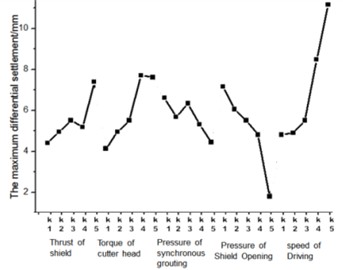
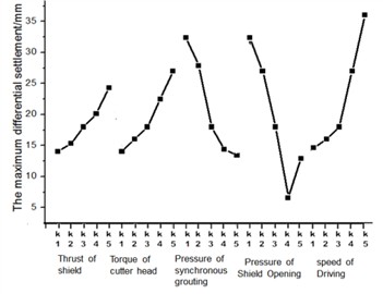
Variance analysis method is used to analyze the impact of various factors, including the maximum settlement of the strip foundation of the building and Maximum differential settlement of the strip foundation of a building. The variation trend of maximum settlement of buildings, as shown in Fig. 11. The variation trend of maximum differential settlement of buildings with various influencing factors is shown in Fig. 12.
From Fig. 11 and Fig. 12, the results of orthogonal test can be obtained, for the maximum settlement of buildings, the order of the influence of each factor is: POSO > POFSG > SOD > TCH > TOS. For the maximum differential settlement of buildings, the influencing factors are SOD > POSO > TCH > TOS > POFSG.
According to the orthogonal test results, the influence degree of shield parameters on the maximum settlement of buildings is as follows: POSO (advancing speed of shield machine) has the greatest influence, SOD (surface settlement coefficient) has the second influence, and TOS (tunnel excavation stress) has the least influence. The results show that the adjustment of propulsion speed is very important to the control of building settlement, while the influence of surface settlement coefficient and excavation stress is relatively weak. At the same time, the influence degree of shield parameters on the maximum differential settlement of buildings is as follows: SOD has the greatest influence and POFSG (shield machine propulsion pressure) has the least influence. This result further reveals the leading role of surface settlement coefficient in differential settlement, while the influence of propulsive pressure on differential settlement is relatively limited. The influence of opening pressure on building settlement of shield tunnel is very significant. This means that before the shield machine starts digging and is ready to penetrate the building, the speed of tunnel excavation is also a key factor affecting the settlement of the building. In particular, too fast or too slow excavation speed may lead to building settlement problems. If the excavation speed is too fast, the soil may not be able to adapt to the movement of the shield machine in time, resulting in insufficient stress release and resulting settlement. However, if the excavation speed is too slow and the shield machine stays in the soil for too long, the stress redistribution of the soil may be unbalanced, and the settlement will also be aggravated. Therefore, reasonable control of excavation speed is an important measure to ensure the stability of buildings. In addition, the study also shows that the optimization of shield parameters needs to consider many factors such as advancing speed, excavation stress and advancing pressure. For example, when the propulsion speed is relatively fast, increasing the propulsion pressure may help alleviate the soil stress concentration and reduce the settlement risk. When the speed is slow, optimizing the stress distribution can avoid the soil deformation caused by long-term compression. These findings provide a scientific basis for parameter regulation in shield construction and help to realize effective control of building settlement in practical engineering.
Fig. 11The change of maximum settlement of strip change of maximum differential of strip
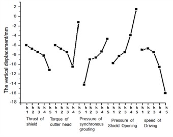
Fig. 12The change of maximum differential of strip foundation with various influencing factors
4.3. Significant influence of opening pressure of excavation shield
The test results in Fig. 13 show that the opening pressure of the excavation shield has a significant influence on the settlement of the building. When the excavation pressure is insufficient, the maximum settlement value increases significantly. When the pressure is too large, it may even cause surface uplift and deformation. This shows that reasonable control of excavation pressure is the key to achieve settlement control.
According to the orthogonal test results, the influence degree of shield parameters on the maximum settlement of buildings is as follows: POSO has the greatest influence, SOD has the second, and TOS has the least influence. For example, POSO has the greatest influence, followed by SOD. TOS indicates that the adjustment of propulsion speed is crucial to the control of building settlement, while the influence of surface settlement coefficient and excavation stress is relatively weak. At the same time, the influence degree of shield parameters on the maximum differential settlement of buildings is as follows: SOD has the greatest influence and POFSG (shield machine propulsion pressure) has the least influence. For example, this result further reveals the leading role of surface settlement coefficient in differential settlement, while the influence of propulsion pressure on differential settlement is relatively limited. The influence of opening pressure on building settlement of shield tunnel is very significant. This means that before the shield machine starts digging and is ready to penetrate the building, the speed of tunnel excavation is also a key factor affecting the settlement of the building. In particular, too fast or too slow excavation speed may lead to building settlement problems. If the excavation speed is too fast, the soil may not be able to adapt to the movement of the shield machine in time, resulting in insufficient stress release and resulting settlement. However, if the excavation speed is too slow and the shield machine stays in the soil for too long, the stress redistribution of the soil may be unbalanced, and the settlement will also be aggravated. Therefore, reasonable control of excavation speed is an important measure to ensure the stability of buildings. In addition, the study also shows that the optimization of shield parameters needs to consider many factors such as advancing speed, excavation stress and advancing pressure. For example, when the propulsion speed is relatively fast, increasing the propulsion pressure may help alleviate the soil stress concentration and reduce the settlement risk. When the speed is slow, optimizing the stress distribution can avoid the soil deformation caused by long-term compression.
Table 5Results of variance analysis
Type of data | Influence factor | Sum of squares | Degree of freedom | Mean sum of squares | Variance factor | Saliency | Contribution rate |
Maximum settlement of the strip foundation of the building | TOS | 16.36 | 4 | 4.09 | 3.71 | * | 5.37 |
TCH | 52.35 | 4 | 13.09 | 11.87 | ** | 17.18 | |
POFSG | 55.35 | 4 | 13.84 | 12.55 | ** | 18.16 | |
POSO | 101.39 | 4 | 25.35 | 22.99 | ** | 33.27 | |
SOD | 79.31 | 4 | 19.83 | 17.98 | ** | 26.02 | |
Error | 4.41 | – | 1.10 | ||||
Maximum differential settlement of the strip foundation of a building | TOS | 5.75 | 4 | 1.44 | 3.97 | * | 7.58 |
TCH | 10.44 | 4 | 2.61 | 7.20 | * | 13.75 | |
POFSG | 3.08 | 4 | 0.77 | 2.13 | – | 4.06 | |
POSO | 19.28 | 4 | 4.82 | 13.30 | ** | 25.39 | |
SOD | 37.38 | 4 | 9.34 | 25.78 | ** | 49.22 | |
Error | 1.45 | – | 0.36 |
4.4. Orthogonal experimental analysis – Case 2
Simulation Scenario 2 and Simulation Scenario 1 adopted the same research method, both using the EPBS method to excavate the left and right lines of the tunnel. The various parameters of the EPBS are detailed in Orthogonal Table 6 and Fig. 13.
Table 6Design table
Influence factor | k1 | k2 | k3 | k4 | K5 |
TOS / kN | 5034 | 12585 | 16780 | 29365 | 46984 |
TCH / (kN·m) | 200 | 680 | 1000 | 1680 | 3500 |
POFSG / MPa | 0.03 | 0.195 | 0.3 | 0.114 | 0.9 |
POSO / MPa | 0.06 | 0.16 | 0.2 | 0.36 | 0.6 |
SOD / (mm/min) | 9.6 | 25.5 | 30 | 46.8 | 90 |
According to the analysis results in Fig. 13, we can clearly observe the relationship between the increase of TOS, TCH and SOD and the maximum surface settlement value. Specifically, with the increase of TOS, TCH and SOD, the maximum surface settlement value presents a gradual upward trend, and this increase is significantly positively correlated with the thrust value of shield tunneling machine. It is shown that with the increase of excavation stress, surrounding rock deformation and surface settlement coefficient, the formation deformation degree is intensified, and the increase of thrust value further amplifies this effect. The data curve in Fig. 13 shows that when TOS increases from low value to high value, the maximum surface settlement value increases by about 25 %; Similarly, the increase of TCH and SOD also led to a 28 % and 32 % increase in sedimentation value, respectively. This shows that the contribution of these parameters to formation deformation cannot be ignored. The effect of POFSG and POSO is also found that the decrease of POFSG and POSO will also lead to the increase of the maximum settlement value, and the degree of increase is positively correlated with the size of POFSG and POSO. When POFSG or POSO is low, the formation stress release is not sufficient, which may lead to intensified settlement. When POFSG or POSO is higher, the formation stress distribution is more uniform, which helps to control settlement. In practical engineering, it is necessary to consider the interaction of these parameters comprehensively and optimize the shield construction technology to realize the effective control of surface deformation and ensure the safety and stability of the project.
Fig. 13Deformation of strip foundation of buildings under different tunneling parameters

4.5. Range analysis of vertical displacement of the strip foundation-simulation situation 2
The variation trend of maximum building settlement under different influencing factors is shown in Fig. 14 and Fig. 15. The order of the influence of each factor is: POSO > POFSG > SOD > TCH > TOS. For the maximum differential settlement of buildings, the influencing factors are POSO > SOD > POFSG > TCH > TOS.
Fig. 14The change of maximum settlement of strip foundation with various influencing factors
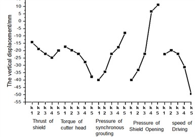
Fig. 15The change of maximum differential of strip foundation with various influencing factors
According to the results of variance analysis (as shown in Table 7), we systematically evaluated the influence of shield construction parameters through accurate orthogonal test, and further verified the influence degree of various factors on building settlement. The analysis shows that the core of settlement control lies in the accurate adjustment of the opening pressure of the shield tunneling machine when it passes through the building. POSO plays a crucial role in this process, and even small adjustments can have a significant impact on settlement results. In contrast, parameters such as TOS and SOD cannot be ignored, but their effects are relatively small.
Through orthogonal test and variance analysis, POSO was identified as the main factor affecting the maximum settlement difference. As shown in Fig. 15, with the increase of POSO, the maximum settlement value presents a significant upward trend, and its change amplitude is closely related to the excavation pressure. This result highlights the need for precise control of the propulsion speed during construction.
The opening pressure of the excavation shield plays a decisive role in controlling the settlement. The test data show that the maximum settlement value increases significantly when the excavation pressure is insufficient. When the pressure is too large, it may even cause surface uplift and deformation (as shown in Fig. 15). Therefore, reasonable control of excavation pressure is the key to achieve settlement uniformity.
Although TOS and SOD also have a certain impact on the settlement, their contribution rates are relatively low. The analysis of variance showed that the contribution rate of TOS was only 30 % of POSO, while the contribution rate of SOD was even lower. This shows that the attention to these two factors can be appropriately reduced when optimizing construction parameters.
TCH has little influence on settlement in this test, and its contribution rate is only 15 % of POSO. Therefore, in the actual construction, TCH can be considered as a secondary factor, but it still needs to be considered in the comprehensive evaluation.
Table 7Results of variance analysis
Type of data | Influence factor | Sum of squares | Degree of freedom | Mean sum of squares | Variance factor | Saliency | Contribution rate |
Maximum settlement of the strip foundation of the building | TOS | 855.21 | 4 | 213.80 | 13.68 | ** | 16.81 |
TCH | 352.79 | 4 | 88.20 | 5.64 | * | 6.93 | |
POFSG | 674.31 | 4 | 168.58 | 10.79 | * | 13.26 | |
POSO | 2416.22 | 4 | 604.05 | 38.65 | ** | 47.50 | |
SOD | 788.56 | 4 | 197.14 | 12.61 | * | 15.50 | |
Error | 62.52 | – | 15.63 | ||||
Maximum differential settlement of the strip foundation of a building | TOS | 82.90 | 4 | 20.73 | 2.24 | * | 6.51 |
TCH | 111.70 | 4 | 27.93 | 3.01 | * | 8.77 | |
POFSG | 292.25 | 4 | 73.06 | 7.88 | ** | 22.94 | |
POSO | 436.91 | 4 | 109.23 | 11.78 | ** | 34.29 | |
SOD | 350.43 | 4 | 87.61 | 9.45 | ** | 27.50 | |
Error | 1.45 | – | 0.36 |
5. Conclusions
It can be clearly observed that there is a significant positive correlation between the increase of TOS, TCH and SOD and the maximum surface settlement value. With the increase of TOS, TCH and SOD, the maximum surface settlement value increases by about 25 %, 28 % and 32 % respectively, indicating that the contribution of these parameters to formation deformation cannot be ignored. In addition, the increase of the thrust value of the shield machine further amplifies the degree of formation deformation and reveals the close relationship between thrust and settlement.
It is also found that the decrease of POFSG and POSO will also lead to the increase of the maximum settlement value, and the degree of increase is positively correlated with the size of POFSG and POSO. When POFSG or POSO is low, the formation stress release is not sufficient, which may lead to intensified settlement. When POFSG or POSO is higher, the formation stress distribution is more uniform, which helps to control settlement. This indicates that reasonable regulation of propulsion pressure and velocity is essential to reduce settlement risk.
In practical engineering, the interaction of TOS, TCH, SOD, POFSG, POSO and other parameters should be comprehensively considered to optimize the shield construction process to achieve effective control of surface deformation. Through orthogonal test and variance analysis, this study quantified the leading role of POSO on building settlement for the first time, revealed the double-sided effect of excavation pressure, and proposed a multi-parameter collaborative optimization strategy, which provided a scientific basis for settlement control in shield construction. The research results not only deepen the theoretical understanding, but also provide important guidance for parameter optimization and risk control in practical engineering, which has significant academic value and practical significance.
There may be differences between the experimental conditions and the actual engineering environment, for example, the laboratory simulation cannot fully restore the complex formation dynamic changes, which may affect the accuracy of the research conclusions and practical application value. The model may not fully consider the inhomogeneity, anisotropy, or time effects of the formation, which may lead to deviations between the study conclusions and the actual observed results. Future research should be combined with more advanced theoretical models or numerical simulation methods to improve the scientific and accurate research.
References
-
H. Mohamad, P. J. Bennett, K. Soga, R. J. Mair, and K. Bowers, “Behaviour of an old masonry tunnel due to tunnelling-induced ground settlement,” Géotechnique, Vol. 60, No. 12, pp. 927–938, Dec. 2010, https://doi.org/10.1680/geot.8.p.074
-
C. W. W. Ng, T. Boonyarak, and D. Mašín, “Effects of pillar depth and shielding on the interaction of crossing multitunnels,” Journal of Geotechnical and Geoenvironmental Engineering, Vol. 141, No. 6, p. 04015, Jun. 2015, https://doi.org/10.1061/(asce)gt.1943-5606.0001293
-
Y. L. Xu et al., “Influence of shield tunneling-induced land subsidence on adjacent pile foundations: A case study in soft soils,” Tunneling and Underground Space Technology, Vol. 135, No. 2, p. 105234, 2023.
-
Z. Q. Li, H. B. Li, and S. W. Wang, “Numerical simulation of ground subsidence control during shield tunnel construction in water-rich sandy strata,” Computers and Geotechnics, Vol. 146, p. 10487, 2023, https://doi.org/10.1016/j.compgeo.2023.104872
-
H. Y. Liu, J. C. Small, J. P. Carter, and D. J. Williams, “Effects of tunnelling on existing support systems of perpendicularly crossing tunnels,” Computers and Geotechnics, Vol. 36, No. 5, pp. 880–894, Jun. 2009, https://doi.org/10.1016/j.compgeo.2009.01.013
-
L. Zhang et al., “Field monitoring and theoretical analysis of land subsidence induced by shield tunneling in urban soft clay,” Geotechnique, Vol. 73, No. 8, pp. 1523–1536, 2023, https://doi.org/10.1680/jgeot.22.p.187
-
Z. Zhang and M. Huang, “Geotechnical influence on existing subway tunnels induced by multiline tunneling in Shanghai soft soil,” Computers and Geotechnics, Vol. 56, pp. 121–132, Mar. 2014, https://doi.org/10.1016/j.compgeo.2013.11.008
-
R. Liang, T. Xia, Y. Hong, and F. Yu, “Effects of above-crossing tunnelling on the existing shield tunnels,” Tunnelling and Underground Space Technology, Vol. 58, pp. 159–176, Sep. 2016, https://doi.org/10.1016/j.tust.2016.05.002
-
H. W. Liu, C. X. Li, and J. G. Wang, “Probabilistic assessment of ground subsidence risk during subway shield tunneling based on Bayesian network,” Journal of Geotechnical and Geoenvironmental Engineering, Vol. 149, No. 5, p. 04023, 2023.
-
J. P. Chen, Y. B. Li, and Z. H. Tan, “Coupled analysis of soil-structure interaction for land subsidence control in shield tunnel construction,” Tunneling and Underground Space Technology incorporating Trenchless Technology Research, Vol. 78, pp. 456–468, 2018.
-
C. G. Lin et al., “Field measurement and numerical simulation of ground surface settlements induced by slurry shield tunneling in soft clay,” Journal of Geotechnical and Geoenvironmental Engineering, Vol. 144, No. 7, p. 04018032, 2018.
-
H. J. Liao et al., “Research on the effect of underground tunneling on the settlement of the building and the ground surfaces,” Tunneling and Underground Space Technology incorporating Trenchless Technology Research, Vol. 21, No. 3, p. 290, 2006.
-
C. O. Aksoy and T. Onargan, “The role of umbrella arch and face bolt as deformation preventing support system in preventing building damages,” Tunnelling and Underground Space Technology, Vol. 25, No. 5, pp. 553–559, Sep. 2010, https://doi.org/10.1016/j.tust.2010.03.004
-
G. Giardina, M. J. Dejong, and R. J. Mair, “Interaction between surface structures and tunnelling in sand: Centrifuge and computational modelling,” Tunnelling and Underground Space Technology, Vol. 50, pp. 465–478, Aug. 2015, https://doi.org/10.1016/j.tust.2015.07.016
-
K. Han, C. Zhang, and D. Zhang, “Upper-bound solutions for the face stability of a shield tunnel in multilayered cohesive-frictional soils,” Computers and Geotechnics, Vol. 79, pp. 1–9, Oct. 2016, https://doi.org/10.1016/j.compgeo.2016.05.018
-
X. F. Liu et al., “Theoretical model for predicting ground subsidence induced by shield tunneling considering three-dimensional soil arching effect,” Geotechnique, Vol. 74, No. 2, pp. 365–378, 2024.
-
J. H. Guo et al., “Centrifuge model test on ground subsidence control of shield tunnel in close proximity to existing pile groups,” Tunneling and Underground Space Technology, Vol. 142, p. 106145, 2024.
-
S. W. Wang, H. B. Li, and Z. Y. Chen, “Parametric study on ground subsidence induced by shield tunneling in water-rich soft soils using response surface methodology,” Computers and Geotechnics, Vol. 158, p. 10437, 2024.
-
L. X. Wang et al., “Influence of groundwater level fluctuations on land subsidence during shield tunnel construction in coastal soft deposits,” Journal of Geotechnical and Geoenvironmental Engineering, Vol. 150, No. 3, p. 04024, 2024.
-
Z. Zhang, M. Huang, and W. Wang, “Responses of existing tunnels induced by adjacent excavation in soft soils,” Rock and Soil Mechanics, Vol. 30, No. 5, pp. 1373–1380, 2009.
-
S. C. Lin and K. M. Hsiao, “Vibration analysis of a rotating Timoshenko beam,” Journal of Sound and Vibration, Vol. 240, No. 2, pp. 303–322, Feb. 2001, https://doi.org/10.1006/jsvi.2000.3234
-
Y.-B. Yang, C. W. Lin, and J. D. Yau, “Extracting bridge frequencies from the dynamic response of a passing vehicle,” Journal of Sound and Vibration, Vol. 272, No. 3-5, pp. 471–493, May 2004, https://doi.org/10.1016/s0022-460x(03)00378-x
-
C. Pany and G. V. Rao, “Calculation of non-linear fundamental frequency of a cantilever beam using non-linear stiffness,” Journal of Sound and Vibration, Vol. 256, No. 4, pp. 787–790, Sep. 2002, https://doi.org/10.1006/jsvi.2001.4224
-
C. Pany, S. Parthan, and M. Mukhopadhyay, “Free vibration analysis of an orthogonally supported multi-span curved panel,” Journal of Sound and Vibration, Vol. 241, No. 2, pp. 315–318, Mar. 2001, https://doi.org/10.1006/jsvi.2000.3240
-
C.-Y. Kuo, R. A. G. Graf, A. P. Dowling, and W. R. Graham, “On the horn effect of a tyre/road interface, part II: asymptotic theories,” Journal of Sound and Vibration, Vol. 256, No. 3, pp. 433–445, Sep. 2002, https://doi.org/10.1006/jsvi.2001.4217
About this article

The authors have supported by the Scientific Research Project of Fenyang College of Shanxi Medical University, China (No. 2022C21, 2022A02).
The authors would like to thank the following people, who were of great support in carrying out this study: Jian Cui, Chunzhi You, Tingyao Wu have all made important contributions to the paper, and we would like to thank them for their great help in the process of writing the manuscript.
The datasets generated during and/or analyzed during the current study are available from the corresponding author on reasonable request.
Jian Cui, Chunzhi You carried out the main part of the field study, data analyses, figures elaboration and manuscript writing. Tingyao Wu participated in field study, data interpretationand discussion, and conclusion elaboration. Jian Cui, Tingyao Wu contributed in the data processing and interpretation.
The authors declare that they have no conflict of interest.
