Abstract
The double earthquake that struck Türkiye on February 6, 2023 killed over 50,000 people. It also caused the collapse of thousands of low-rise reinforced concrete structures in the seismic area, resulting in incredible damage. To study the reasons for the progressive collapse of numerous buildings, a nine-story concrete frame structure was established in this study, and the elastic-plastic time-history analysis under the double earthquake was performed. The element failure criterion was defined using the max equivalent compressive strain, refining the damage initiation point and transmission path of the proposed structure. The results showed that: 1. The natural period of vibration of the low-rise concrete frame structure in the seismic area is in the peak spectral acceleration region of the first earthquake, which maximizes the earthquake damage force. 2. The first strong earthquake disabled the main load-bearing columns on the ground floor of the structure, resulting in collapse within a few seconds of the second earthquake. 3. The seismic damage investigation showed that the low-rise frame structure had insufficient longitudinal reinforcement laps, insufficient transverse reinforcement and stirrups, and weak embeddedness between longitudinal bars and concrete. These issues have amplified the damage degree. 4. Despite the comprehensive building seismic regulations in Türkiye, the most pressing problem may be the long-term regulatory failure of the authorities.
Highlights
- The double earthquake that struck Turkey caused the collapse of thousands of low-rise reinforced concrete structures.
- A typical local nine-story concrete frame structure was established in this study, and the elastic-plastic time-history analysis under the double earthquake was performed.
- The element failure criterion was defined using the max equivalent compressive strain, refining the damage initiation point and transmission path of the proposed structure.
- The seismic damage investigation showed that the low-rise frame structure had insufficient longitudinal reinforcement laps, insufficient transverse reinforcement and stirrups, and weak embeddedness between longitudinal bars and concrete.
- Despite the comprehensive building seismic regulations in Turkey, the most pressing problem may be the long-term regulatory failure of the authorities.
1. Introduction
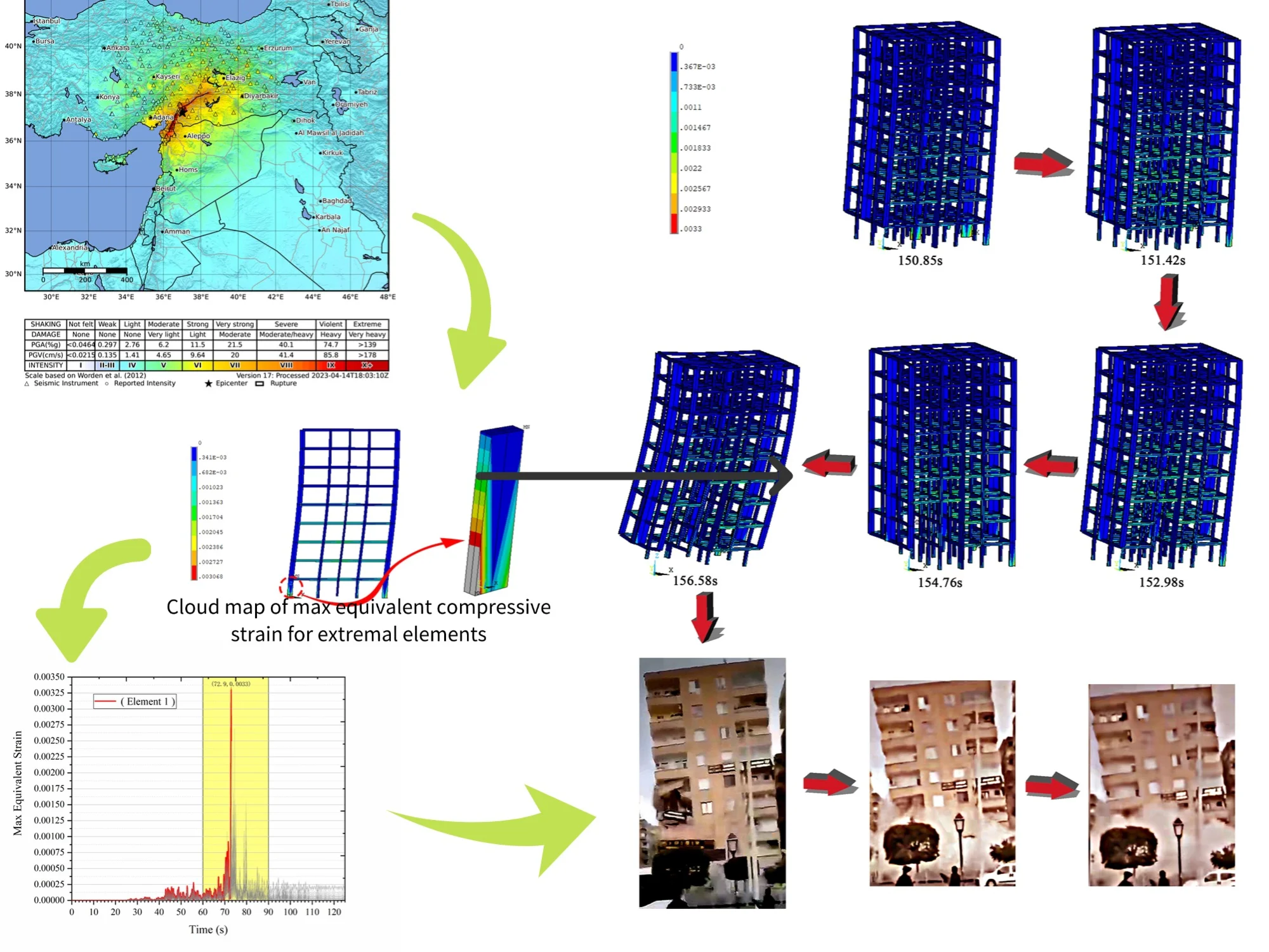
A magnitude-7.8 earthquake hit southeastern Türkiye and northern Syria in the early hours of the morning of 6 February. According to the latest data from the Turkish Disaster and Emergency Management Authority of Türkiye (AFAD), at least 50,399 people are known to have lost their lives, with thousands more injured. The quake was followed by a magnitude-7.6 event approximately 9 hours later, as well as more than 200 aftershocks. Fig. 1 shows the Macro seismic Intensity Map of these two earthquakes, with data from United States Geological Survey (USGS).
As shown in Fig. 1, the epicenter of the two earthquakes is far apart, but there are still many adjacent radiated parts in the epicentral area. Despite the significant distance between the two seismic events, stress transfer occurred, influencing structural failure patterns. Alkan provided substantial insights into this phenomenon [2]. Several low-rise concrete frame structures barely surviving the first strong earthquake collapsed during the second earthquake. After the first earthquake, local people flooded the streets, and some people used their cell phones to film post-earthquake scenes, capturing many clips of the collapse process. These video clips provide valuable information for studying progressive collapse mechanisms of low-rise concrete frame structures.
According to past experience, building collapse is undoubtedly the most direct and important cause of tragic earthquake hazards. The American Society of Civil Engineers (ASCE) defines progressive collapse as: Under normal service conditions, the structure undergoes initial local damage due to an unexpected event, and the damage is transmitted along the components, eventually leading to the collapse of the entire structure or the damage that is disproportionate to the initial structural damage [3]. Since the collapse of the Ronan Point Apartments in England in 1968, the progressive collapse has been studied in Europe and the United States for more than 50 years. European Committee for Standardization [4], British Standards Institution [5], United States General Services Administration [6], and Unified Facilities Criteria [7] specifically described the design methods for preventing the progressive collapse of structures.
Fig. 1Macroseismic intensity map of two earthquakes in Türkiye [1]
![Macroseismic intensity map of two earthquakes in Türkiye [1]](https://static-01.extrica.com/articles/24700/24700-img1.jpg)
a) The magnitude-7.8 earthquake
![Macroseismic intensity map of two earthquakes in Türkiye [1]](https://static-01.extrica.com/articles/24700/24700-img2.jpg)
b) The magnitude-7.6 earthquake
Because the collapse starts locally from the weakest component of the structure, determining the initial point of the collapse and the transmission path of collapse damage can ensure the application of targeted strengthening measures, thus reducing building collapse and protecting human life and property. However, it is difficult to achieve this goal due to the uncertainty of ground vibrations, the diversity of buildings, and the complexity of their structures.
For important structural projects, shaking table experiments with scaled-down models are occasionally adopted in actual engineering to determine the weak points of the structure. However, this method is time-consuming and labor-intensive, with many problems inherent in the shaking table experiment by the scaled-down model (insufficient quality, inaccurate P-Δ effects, etc.). An alternative approach is to use finite element software to build a reasonable numerical model of the structure and simulate the structure collapse by inputting ground vibrations [8-9]. However, due to the uncertainty of ground shaking, the diversity of building types, and the complexity of the structure, some finite element models cannot be effectively applied in seismic collapse analysis to prevent progressive collapse.
High-rise buildings are considered one of the most common structures nowadays due to the population growth, especially in crowded towns. The most effective passive vibration control and seismic resistance options in a reinforced concrete high-rise building are the base isolation and the tuned mass damper system. Many options, which may be suitable or not for different soil types, with different types of bearing systems, like rubber isolator, friction pendulum isolator and tension/compression isolator, are investigated to resist the base straining actions under five different earthquakes by Kontoni and Farghaly (2019) [10]. Diagrid structures have been introduced as a fairly modem lateral load-resisting system in the design of high-rise buildings. A novel diagrid system called tube-in-tube diagrid building is introduced and assessed through pushover and incremental dynamic analyses [11]. Response spectrum analysis and comparative analysis of Hengda Group super high-rise building in Jinan City are conducted using two software applications [12]. Pejovic and Serdar perform a detailed probabilistic seismic damage analysis of RC high-rise buildings and as a result, the damage states and appropriate performance levels were defined in a quantitative manner. To evaluate methods of reducing the risk of collision between adjacent twin high-rise buildings [13]. Farghaly and Kontoni investigates three vibration control methods to reduce the risk of collision due to five different earthquakes for the case of two adjacent reinforced concrete twin high-rise buildings of 15 floors height without gap distance between them, founded on raft foundation supported on piles inside a liquefaction-prone soil [14]. Currently, an increasing number of seismologists are shifting their research focus to high-rise reinforced concrete buildings and neglecting the large number of collapsed low-rise reinforced concrete structures in the recent earthquake in Türkiye.
In this study, the finite element software ANSYS was used to model a common low-rise reinforced concrete frame structure in Türkiye. The life-death element and restart analysis functions were adopted to simulate the collapse process under two strong ground-shaking inputs. This analysis aims to reveal the collapse mechanism of thousands of local low-rise concrete frame structures, thus providing some reference basis for designing low-rise reinforced concrete frame structures against progressive collapse.
2. Finite element model
2.1. Model overview
A nine-story reinforced concrete frame structure was selected for finite element modeling based on the video of the collapse taken by local citizens in Türkiye and the earthquake damage investigation by the rescue team (Fig. 2). A nine-story reinforced concrete frame structure was selected for finite element modeling based on the video of the collapse taken by local citizens in Türkiye and the earthquake damage investigation by the rescue team (Fig. 2). To ensure the rationality and reliability of the selected model, the structural dimensions and material properties were determined based on field surveys and the Turkish building code. Additionally, earthquake damage investigation reports provided supplementary validation of the model selection.
Fig. 2The selected model

a) Frame structure before collapse
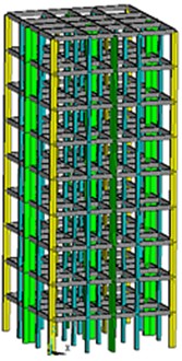
b) Finite element model
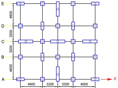
The structure is symmetrical in longitudinal and transverse directions, with a floor height of 3.3 m, and the footings of the columns are assumed to be ideally cemented to the ground. According to the Turkish Seismic Code, the typical floor height of reinforced concrete buildings is approximately 3.0 m. In this study, the floor height was adjusted to reflect this standard. While the selected building is based on common construction practices in Türkiye, certain assumptions were made in the finite element modeling process due to limited access to detailed design documents of collapsed buildings. Future studies could integrate more field survey data for improved model accuracy. The sizes of the column cross-section are: 1) 400×400 mm; 2) 800×300 mm; 3) 1500×300 mm. The cross-section of the beam is in size of 300×250 mm, and the pan view of the standard story is shown in Fig. 3. The Turkish Earthquake Code specifies that the minimum characteristic compressive strength of concrete for buildings in the seismic area is 20 MPa [15]. Therefore, the concrete was set with the characteristic compressive strength of 20 MPa, a mass density of 2700 kg/m3, modulus of elasticity of 30 GPa, and Poisson’s ratio of 0.2.
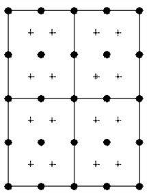
Fig. 3Pan view of the standard story
2.2. The constitutive relationship of concrete
The multi-linear kinematic reinforcement model in the ANSYS material library is selected as the constitutive relationship model for the concrete, and the parameter settings are shown in Fig. 4. In this model, segment 0-1 is the linear elastic phase; point 4 represents the ultimate compressive strength, with the corresponding strain = 0.002; the descending segment is a straight line with a slope of 15 %, and the final compressive strain is = 0.0033 [16].
Fig. 4Multi-linear kinematic hardening model
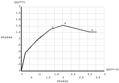
Fig. 5Section, grids, and section nodes
2.3. Element failure criterion
The model uses Beam189 element to simulate beams and columns. Beam189 is a 3D quadratic finite strain beam for the analysis of beam structures (in sizes from slender to moderately short and thick). This element is based on the Timoshenko beam theory and considers the effect of shear deformation. Each node has up to seven degrees of freedom: The transversal displacement of the nodal coordinate system in , , and directions, axial rotation of the coordinate system around , , and axes, and the wrapping of the cross-section. These degrees of freedom are suitable for linear, large angle rotation, and nonlinear large strain problems. According to the default properties, the cross-section is divided into four grids containing eight points each (Fig. 5).
Based on the birth-death element property of the Beam189, the cell is “killed” when its compression strain exceeds = 0.0033. When an actual structure suffers damage from the earthquake, the concrete is gradually crushed, followed by the disabling of the entire component under the tensile reinforcement yields [17]. To reduce the computational effort, it is assumed that the steel reinforcement also yields rapidly when the concrete is crushed, and the contact forces on the other components caused by the falling components are neglected.
3. Collapse damage analysis
3.1. Numerical simulation of the 7.8 magnitude earthquake
The seismic waves in the east-west direction of station 3123 during the 7.8 magnitude earthquake in Türkiye (Fig. 6) are input to the structure along the -axis (Fig. 3). The displacement time history of a corner point at the top of the structure is shown in Fig. 7. At this time, the whole structure does not collapse, and the top layer displacement significantly fluctuates from 70 s to 80 s and then stabilizes.
Fig. 6Seismic record in the east-west direction of station 3123 during the Mw7.8 earthquake
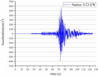
Fig. 7Displacement time history of the top layer
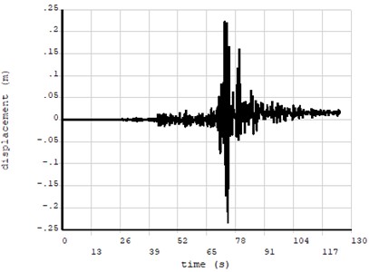
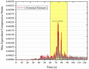
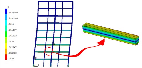
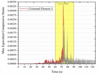
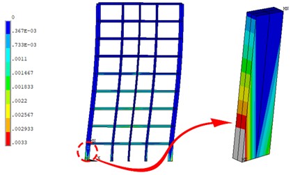
Fig. 8a) Time history of max equivalent compressive strain for all elements along the A-axis; b) cloud map of max equivalent compressive strain for extremal elements
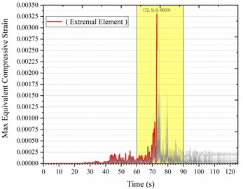
a)
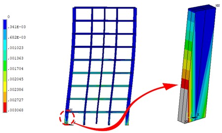
b)
It is found that the stress-strain mainly occurs in the elements along the -axis, while the stress-strain of the elements perpendicular to the -axis is smaller. To further examine the local damage degree and damage initiation element of the structure, the whole structure is divided into five plane frames (A, B, C, D, and E) along the -axis (Fig. 3).
The time history curve of the max equivalent compressive strain for each plane frame element and the cloud map of the max equivalent compressive strain for extremal elements are plotted (Fig. 8-12).
Fig. 9a) Time history of max equivalent compressive strain for all elements along the B-axis; b) cloud map of max equivalent compressive strain for extremal elements

a)
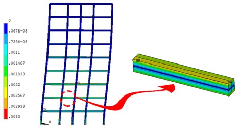
b)
Fig. 10a) Time history of max equivalent compressive strain for all elements along the C-axis; b) cloud map of max equivalent compressive strain for extremal elements
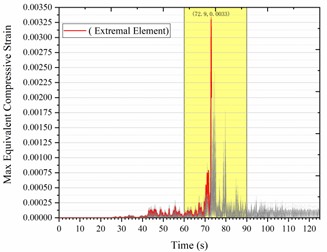
a)
b)
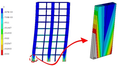
Fig. 11a) Time history of max equivalent compressive strain for all elements along the D-axis; b) cloud map of max equivalent compressive strain for extremal elements
a)
b)
Although the structure does not collapse, the material in some areas of the first lower column on the left side of the A, C, and E axes already exceeds the ultimate compressive strain limit at 72.9 s (Fig. 4), failing to withstand the earthquake forces. In addition, the middle section of the beam on the second floor in the B and C axes fails to reach the limit of compressive strain, but it still shows a relatively large compressive strain of 0.0022.
Fig. 12a) Time history of max equivalent compressive strain for all elements along the E-axis; b) cloud map of max equivalent compressive strain for extremal elements
a)
b)
3.2. Numerical simulation of the 7.6 magnitude earthquake
In the first strong earthquake (Mw = 7.8), the 9-story concrete frame structure did not collapse directly, but three core load-bearing columns of the ground floor failed. They could not bear the vertical load of the structure and the lateral load of the ground vibration, which set the potential for later collapse. The findings of Işk suggest that failure in reinforced concrete buildings under seismic loading is often attributed to insufficient shear strength and poor reinforcement detailing [18]. These factors were also evident in the investigated collapse cases, further explaining why the structure experienced progressive failure.
Fig. 13Seismic record in the east-west direction of station 4612 during the Mw7.6 earthquake
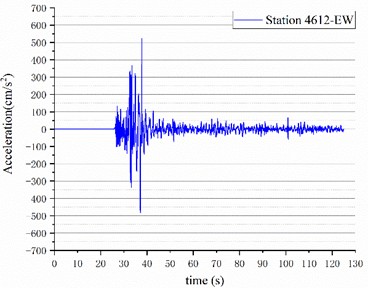
Fig. 14Displacement time history of the top layer
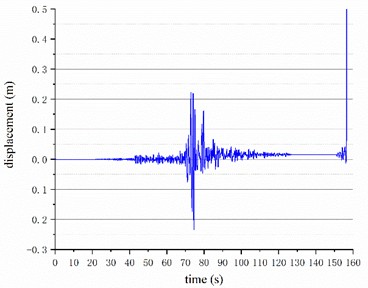
About 9 hours later, the second strong earthquake (Mw = 7.6) occurred, inputting seismic waves (Fig. 13) along the -axis (Fig. 3) to the structure that had experienced plastic deformation in the east-west direction of station 4612. The total displacement time history of two earthquakes at a corner point on the top floor of the structure is shown in Fig. 14. It can be seen that the peak region of the second earthquake starts at 25.84 s, which is 150.85 s of the overall earthquake time. After the seismic action is applied to the structure, the displacement of the top floor increases linearly, and the structure collapses at 156.58 s of the overall time.
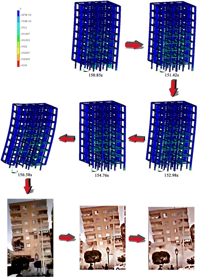
The entire collapse of the structure was simulated, and the actual collapse was photographed by local citizens in Türkiye, as shown in Fig. 15. The disabled elements were “killed” with the birth-death element function of the software. At 150.85 s, three columns on the left side of the bottom floor of the structure failed, and the stress concentration of the structure was transferred to the column of section 3 on the ground floor (Fig. 3); At 151.42 s, the column of section 3 on the ground floor of the structure failed; At 152.98 s, the support of the main load-bearing columns at the ground floor was lost, and the stresses started to transfer to the frame structure beams, leading to the failure of several low-rise central beams; At 154.76 s, the bottom column continued to fail, and the failed beam progressed from the middle to the sides of the structure; At 156.58 s, the damage of the beams and columns at the lower level gradually progressed upward, resulting in the final collapse of the entire structure. According to the actual collapse process of the structure filmed by Turkish citizens, it was found that the left bottom column of this low-rise concrete frame structure failed, leading to the overall collapse of the structure.
Fig. 15Simulated collapse process of low-rise concrete frame structure and actual collapse process
4. Discussion
The most notable aspects of the collapse process are: 1. Why the left beam of the actual structure on the 4th and 5th floors appeared to be damaged at the same time as the ground floor columns, while no significant damage occurred to the beams on the right; 2. The simulated structure lasted for approximately 6 seconds from the time it was subjected to the second earthquake load until it completely collapsed, why the actual structure collapsed much faster and was flattened by the seismic force in only 2 seconds; 3. Why did the double earthquake cause a massive collapse of low-rise concrete frame structures in Türkiye, resulting in tens of thousands of casualties?
Fig. 16Response spectrum of the double earthquake in Türkiye
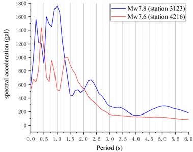
Table 1The mode of vibration information for 9-storey RC frame structure
Modal order | Period (s) | Participation coefficient of vibration mode mass | Cumulative participation coefficient of vibration mode mass |
1 | 1.2208 | 0.38000000 | 0.38 |
2 | 1.2510 | 0.38000000 | 0.76 |
3 | 1.2625 | 0.00011050 | 0.76 |
4 | 3.8640 | 0.05947000 | 0.82 |
5 | 3.8855 | 0.05948000 | 0.88 |
6 | 3.9173 | 0.00001817 | 0.88 |
7 | 4.0890 | 0.02599000 | 0.90 |
8 | 4.6816 | 0.02599000 | 0.93 |
It can be seen from Fig. 16 and Table 1 that the natural period of vibration of the low-rise concrete frame structure is around 1.2 s, which is exactly in the peak spectral acceleration region of the first Mw7.8 earthquake, maximizing the damaging effect. This result generally explains the damage failure of the bottom column on the left side of the structure under the simulated first ground-shaking action. The natural period of vibration cycle of the structure changes after the damage. Although it is not in the peak region of the Mw7.6 earthquake, the overall structure still collapses within a short period due to the failure of the main bearing components.
Additionally, the ultimate reason for the devastation was clear in the mangled ruins: unreinforced brick masonry, low-rise concrete frames, lift slab, and non-ductile concrete. Severe damage was amplified because most existing buildings are low-rise brick structures that are constructed very close to each other [19]. In Türkiye, vulnerabilities persist despite the existence of an appropriate earthquake-resistant building code. Various failures due to insufficient lap-splices of column reinforcement, insufficient amount and detailing of transverse bars and insufficient shear strength of a short column [20]. In order to increase earthquake resilience, building codes need to both exist and be followed. Yet depending on social and political circumstances that may be difficult. Nevertheless, a poorly regulated construction industry in a region with known seismic risk is the real killer [21].
In this study, only a low-rise concrete frame structure in Türkiye under a double earthquake was analyzed for progressive collapse. Although it cannot represent all types of buildings, it reflects the low-level seismic protection of buildings in Türkiye. A large number of low-rise concrete frame structures do not follow the concept of “strong columns and weak beams”. In the event of a strong earthquake, the damage to the lower-level columns occurs before the beams, which is undoubtedly fatal. The risk of a strong earthquake in the future remains high, and local governments must learn from the experience, insist on the people-oriented concept, and strengthen the enforcement of regulatory building codes.
References
-
“Event page of the M7.8 and M7.5 Kahramanmaraş Earthquake Sequence,” US Geological Survey, 2023.
-
H. Alkan, A. Büyüksaraç, and Bektaş, “Investigation of earthquake sequence and stress transfer in the eastern anatolia fault zone by coulomb stress analysis,” Turkish Journal of Earth Sciences, Vol. 33, No. 1, pp. 56–68, Jan. 2024, https://doi.org/10.55730/1300-0985.1898
-
“Minimum design loads for buildings and other structures,” American Society of Civil Engineers, 2005.
-
“Actions on structures,” Eurocode 1, European Committee for Standardization, 2006.
-
“Structural use of concrete,” BS 8110, British Standards Institution, 1997.
-
“Progressive collapse analysis and design guidelines for new federal office buildings and major modernization project,” United States General Services Administration, Washington, D.C., United States General Services Administration, Washington, 2003.
-
“Design of structures to resist progressive collapse,” Department of Defense, Washington, 2005.
-
X. Lin, P. Pan, and L. Ye, “Analysis of the damage mechanism of a typical RC frame in Wenchuan Earthquake,” (in Chinese), China Civil Engineering Journal, Vol. 42, No. 5, pp. 13–20, 2009.
-
X. Lu et al., “Numerical models for earthquake induced progressive collapse of high-rise buildings,” Engineering Mechanics, Vol. 27, No. 11, pp. 64–70, 2010.
-
D.-P. N. Kontoni and A. A. Farghaly, “The effect of base isolation and tuned mass dampers on the seismic response of RC high-rise buildings considering soil-structure interaction,” Earthquakes and Structures, Vol. 17, No. 4, pp. 425–434, Oct. 2019, https://doi.org/10.12989/eas.2019.17.4.425
-
A. Khatami, M. Heshmati, and A. A. Aghakouchak, “Collapse assessment and seismic performance factors in tall tube-in-tube diagrid buildings,” Earthquakes and Structures, Vol. 19, No. 3, pp. 197–214, Sep. 2020, https://doi.org/10.12989/eas.2020.19.3.197
-
X. Zhang, Q. Ren, W. Liu, S. Yang, and Y. Zhou, “Seismic design and elastic-plastic analysis of the hengda group super high-rise office buildings,” Earthquakes and Structures, Vol. 19, No. 3, pp. 175–188, Sep. 2020, https://doi.org/10.12989/eas.2020.19.3.175
-
J. R. Pejovic and N. N. Serdar, “Estimation of inter-story drifts at onset of damage states for RC high-rise buildings,” Earthquakes and Structures, Vol. 21, No. 1, pp. 63–78, Jul. 2021, https://doi.org/10.12989/eas.2021.21.1.063
-
A. A. Farghaly and D.-P. N. Kontoni, “Mitigation of seismic pounding between RC twin high-rise buildings with piled raft foundation considering SSI,” Earthquakes and Structures, Vol. 22, No. 6, pp. 625–635, Jun. 2022, https://doi.org/10.12989/eas.2022.22.6.625
-
“Ministry of Public Works and Settlement Government of Republic of Türkiye,” Turkish seismic code, 2008.
-
J. Wang, “Nonlinear finite element analysis on reinforced concrete structures,” (in Chinese), Shanxi Science and Technique Press, Xi’an, 2010.
-
Q. Feng, S. Jiao, and Y. Liu, “Research on damage to RC frame subjected to seismic loading,” Earthquake Engineering and Engineering Vibration, Vol. 22, No. 3, pp. 52–55, 2002, https://doi.org/10.13197/j.eeev.2002.03.009
-
E. Işık et al., “Field reconnaissance and earthquake vulnerability of the RC buildings in Adıyaman during 2023 Türkiye Earthquakes,” Applied Sciences, Vol. 14, No. 7, p. 2860, Mar. 2024, https://doi.org/10.3390/app14072860
-
M. Naddaf, “Turkey-Syria earthquake: what scientists know,” Nature, Vol. 614, No. 7948, pp. 398–399, Feb. 2023, https://doi.org/10.1038/d41586-023-00364-y.
-
A. Ilki and Z. Celep, “Earthquakes, existing buildings and seismic design codes in Turkey,” Arabian Journal for Science and Engineering, Vol. 37, No. 2, pp. 365–380, Jan. 2012, https://doi.org/10.1007/s13369-012-0183-8
-
L. Dal Zilio and J.-P. Ampuero, “Earthquake doublet in Turkey and Syria,” Communications Earth and Environment, Vol. 4, No. 1, p. 71, Mar. 2023, https://doi.org/10.1038/s43247-023-00747-z
About this article

The support of Frontier Research Team of Kunming University 2023 is gratefully acknowledged. The authors also acknowledge the financial support from the Yunnan Fundamental Research Project (Grant No. 202101AT070144, Grant No. 202401CF070004) and Yunnan Province Foreign Talent Introduction Special Project – Key Foreign Expert Project (Grant No. 202505AO120030). The authors also acknowledge the support of Kunming University Science and Technology Innovation Team 2020.
The datasets generated during and/or analyzed during the current study are available from the corresponding author on reasonable request.
Zhigang Qiu: Study conception and design, data collection, analysis and interpretation of results. Liwei Yang: draft manuscript preparation.
The authors declare that they have no conflict of interest.
