Abstract
In order to investigate the deformation behavior, mechanical characteristics of connections, and failure mode of translational precast concrete wall-panels under earthquake loading, a full-scale two-story steel frame model was designed. This test model consisted of 12 precast concrete wall-panels connected with fixed connections at the bottom end and translational-type connections at the top end. This model passed the shaking table testing, and the results demonstrate that the translational-type precast concrete exterior wall panel can ensure the sufficient relative displacement between the wall panel and the main structure under large earthquake loads. It has sufficient capacity to adapt the deformation between the main structure and the wall panels. During the test, localized cracking was observed on the wall panel, while all connections remained in elastic state. The connections between precast concrete exterior wall panels exhibited good performance, that indicates it is an effective tool to protect frame building hangings with exterior wall panels under strong earthquake events.
Highlights
- A translational-type precast-concrete exterior wall panel is proposed.
- Full-scale shaking table test and numerical analysis were performed to validate the performance.
- The translation-type connection ensure the wall panel remains in elastic range under strong earthquakes.
1. Introduction
The seismic performance of buildings is an important aspect of structural engineering, particularly in regions prone to earthquakes. Steel frames with precast concrete exterior wall panels have gained popularity in recent years due to their advantages in terms of their rapid assembly, environmental sustainability, and versatile architectural design. However, the application of precast concrete exterior does not automatically ensure the seismic robustness of the entire building structure. Recent studies and observations after earthquake events have highlighted the potential weaknesses of conventional exterior walls in steel-framed buildings, as they can sustain severe damage or even collapse due to the effects of inter-story drift [1, 2]. Critically, the collapse of these exterior walls can result in falling debris, which could cause the damage of both interior and exterior structures and result in injuries or fatalities during seismic events. Therefore, to enhance the application of exterior wall panels in engineering projects, further research on the seismic behavior of these structures is required.
The integration of exterior wall panels and frame structures remains the primary factor impeding the advancement of prefabricated steel buildings. To elucidate the lateral stiffness and deformation capacity of the wall panels and main steel structure during earthquakes, researchers have conducted a series of studies on the seismic performance of the entire steel structure-wall panel system. Zhou et al. [3] proposed the use of fiber cement panels (FCP) composite external walls to improve the seismic performance of steel frames. The study conducted a hysteretic loading test and a nonlinear dynamic time-history analysis of a six-story steel frame model with and without the FCP composite external wall. Zhang et al. [4] proposed new prefabricated autoclaved lightweight concrete (ALC) connectors to enhance the seismic performance of steel frames. The experimental results indicated that the frames of the new connectors were more reliable than the traditional connector and showed excellent performance in resisting seismic loading. Hou et al. [5] focused on a new type of energy-dissipating exterior wall system for enhancing the seismic performance of low-rise steel moment-resisting frame (MRF) buildings. The study developed a computer model for the energy-dissipating exterior wall system and introduced the system in a representative 2-story MRF demonstration building for the rehabilitation purpose. The computer simulations showed that the energy-dissipating exterior wall system reduced both transient and residual inter-story drift angle responses in the demonstration building and established a useful criterion for a future design of the exterior wall system. Li et al. [6], Tian et al. [7], and Hu et al. [8] conducted experimental and numerical simulation studies on the lateral resistance and dynamic characteristics of steel frames with aerated concrete exterior wall panels. They investigated the contribution of lateral stiffness of the wall panels. Wang et al. [9], Qiao et al. [10], and Lameiras et al. [11] conducted shaking table tests on frame structures with new insulation filling composite wall panels. They observed that this type of wall panel can improve the lateral stiffness and damping ratio of the entire structure. Although the new wall panels are designed to enhance the seismic performance of the whole structure in the above studies, the research results are not directly applicable to practical projects.
Several studies were conducted to enhance the seismic performance of ordinary concrete exterior wall panels. Guo et al. [12] demonstrated through quasi-static testing that the exterior wall panel structure made of flexible steel frames exhibited excellent ductility. Zhang et al. [13] proposed semi-rigid steel frames infilled with prefabricated damping wall panels that incorporate uncoupling mechanisms and sliding joints to prevent detrimental infill-frame interaction. The quasi-static test conducted in this study showed that the prefabricated damping wall panels had considerable deformation capacity, while the infilled steel frames exhibited seismic behavior similar to bare steel frames without infill. Hou et al. [14] investigated the seismic performance of external ceramsite reinforced concrete composite wall panels with flexible links, and found that the slip, rotation, and deformation of flexible connections during earthquakes can retard the stiffness degradation of the entire structure. Dao et al. [15] analyzed the seismic performance of a new light-frame cold-formed steel-frame system with floor trusses, open panels, V-braced panels, columns, and connections. The results indicated that the system exhibited good ductility, owing to the screwed plate connections located between the light-gauge members and between the light-gauge members and square columns. The frame system demonstrated satisfactory performance at four stories, making it a feasible option for mid-rise construction in seismic regions worldwide. Wang et al. [16] studied the effect of flexible damping connectors on the seismic performance of externally hung concrete composite wall panels through shaking table testing. The researchers found that the flexible damping connectors externally hung on the wall panels improved the interlaminar deformation uniformity of a braced steel frame fabricated with layered structure, and exhibited good seismic performance and post-earthquake recoverability. Chong et al. [17] investigated the seismic performance of exterior wall panels with a pair of U-shaped steel plate energy absorbers, and the results demonstrated that in case of the crawler-type rolling deformation, the U-shaped steel plate energy absorber improved the energy dissipation capacity and deformation performance of the overall structure. Longjam and Shirai [18] evaluated the transfer function for displacement and acceleration of the mainframe and subframe under various structural parameters using a two-degrees-of-freedom model. The researchers found that after setting an optimal negative stiffness and damping at the connecting portion, the peak amplitude of the transfer function of the mainframe can significantly reduce as compared to the reference-controlled case without negative stiffness.
The aforementioned studies suggest that the usage of flexible connections and energy dissipation devices is a promising strategy for enhancing the seismic performance of the entire structure, including the steel structure and precast concrete exterior wall. In a previous work, the authors of this paper [19] proposed an initial design method for translational precast concrete exterior wall panels, which involves fixing the bottom end and sliding the top end for connecting the panels. However, the seismic performance of this design has not been systematically investigated yet.
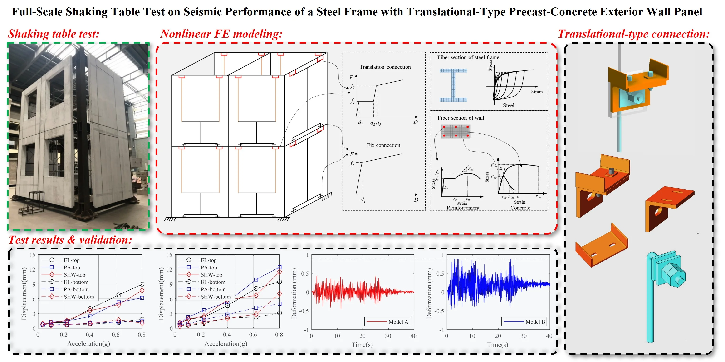
In the present study, a full-scale shaking table test was conducted on translational precast concrete exterior wall panels, based on a practical project, to investigate their seismic performance and deformation characteristics. The test examined the mechanical deformation performance, failure mode, and failure mechanism of the connectors of the precast wall panel under different seismic fortification levels, as well as the mechanical deformation performance, cracking failure mode, and failure mechanism of the wall panel under different seismic fortification levels. Additionally, the study investigated the changes in the width of the panel joint under seismic action and the exterior wall panel ability to adapt to the deformation of the main structure.
2. Experimental program
2.1. Prototype building
The experiment made for this study is based on an assembled composite structure in China, as shown in Fig. 1. The structure has 28 floors above the ground and one floor underground. The total height of the structure is 96.3 m with a floor height of 3.3 m. The load-bearing system of the structure adopts a cast-in-place concrete shear wall incorporating with steel frames. The vertical components of frames are concrete-filled steel tubular columns, and the horizontal components are steel beams and concrete plates. The precast concrete exterior wall panels are adopted in the east, west and north sides of the building. Fig. 2 illustrates the position diagram of the precast concrete exterior wall panels for a standard floor.
Fig. 1Prototype building
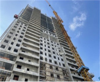
Fig. 2Arrangement scheme of precast concrete exterior wall panels for standard floor
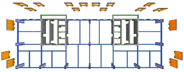
In order to release the deformation constraint of the steel frame caused by exterior wall panels, translational-type connections are used to connect wall panels and the steel frame. Fig. 3 presents details of the precast concrete exterior wall panel and its connections. The bottom connections are the load-bearing nodes (Fig. 3(b)), which can be considered as a hinge between the exterior wall panel and the steel beam. This connection can maintain consistent deformation between the exterior wall panel and the main structure. The gap between the bottom end of panels and floors can be filled with cement mortar for water prevention, sound insulation and smoke prevention. The top connections are the non-load-bearing nodes (Fig. 3(c)), which allow a relative displacement between the exterior wall panel and the main structure. The effective connections of the precast concrete exterior wall panels and the main steel beam are achieved through the use of channel steel and angle steel, thereby avoiding the need to open holes on the flange of the main steel beam and weaken its bearing capacity.
Fig. 3Details of precast concrete exterior wall panel and its connections
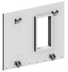
a) Exterior wall panel
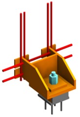
b) Bottom connection
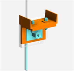
c) Top connection
2.2. Experimental model design
The test was carried out on a shaking table system at the Tongji University. Table 1 presents the basic parameters of the shaking table used in the experiment. The study utilized full-scale precast concrete exterior wall panels assembled into a prototype structure. A two-story steel frame model was constructed with the consideration of the size of the exterior wall panels and the shaking table. The heights of the first and second floors of the steel frame were 3.57 m and 3.3 m, respectively. The total height of the two-story steel frame, including the height of column base and column top extension, was approximately 7.17 m. The top plane size of the steel frame is 5.5 m×3.5 m. The columns and beams of the steel frame were made of Q345 steel I-beams, with a steel column, main steel beam, and secondary steel beam being of the HW300×300×10×15, HN400×200×8×13, and HM250×175×7×11 types, respectively. Two types of precast concrete exterior wall panels, W-1 and W-2, were hung in different directions of the steel frame. The concrete strength grade of the wall panels is C40, and the average measured concrete strength was 44.5 MPa based on an on-site test using a ZC-3 type concrete rebound tester. The thickness of the wall panel is 120 mm. Since the wall panels are made of precast concrete, its age is more than 28 days at the time of testing. For the W-1 wall panels, the window dimensions are 1.4 m×1.6 m, while the W-2 wall panels do not have windows. Specifically, for each floor, two W-1 panels were installed at both sides of the steel frame in the length direction (Y direction), and one W-2 panel was installed in the width direction ( direction). Fig. 4 shows the plan view of wall panels on the steel frame. The total weight of the test model was approximately 37 tons, which includes the weight of the model steel frame and exterior wall panels, totaling around 9 tons and 28.04 tons, respectively. The specifications of the exterior wall panels used in the test are listed in Table 2, and Fig. 4 illustrates the structural elements of the test model examined in the present study.
Table 1Basic performance parameters of shaking table
Parameters | Technical specification |
Table size (m) | 6×4 |
Maximum bearing capacity (t) | 70 |
Degrees of freedom | 3 |
Maximum displacement (mm) | , direction ±500 |
Maximum velocity (mm/s) | , direction ±1000 |
Maximum acceleration (g) | , direction ±1.5 |
Range of operating frequency (Hz) | 0.1-50 |
Overturning moment (t·m) | 400 |
Table 2Specification of precast concrete exterior wall panels for testing
Wall panel specifications | Width (mm) | Height (mm) | Weight (t) |
W-1 | 2400 | 3275 | 2.10 |
W-2 | 2975 | 3275 | 2.81 |
Fig. 4Structural elements of test model
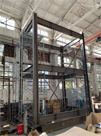
a) Steel frame
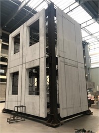
b) Steel frame with exterior wall panels
2.3. Instrumentation
The test specimen was equipped with 210 sensors, consisting of 30 accelerometers, 62 displacement transducers, and 118 strain gauges. Specifically, 6 single-degree accelerometers (A) were divided into 3 groups, which were arranged at corner and center points of each floor for measuring accelerations of the steel frame along the and directions. In addition, 2 accelerometers were also installed at each wall panel, 18 displacement transducers (D) were installed at the steel frame, with 3 displacement transducers along the and directions on each floor. A total of 32 displacement transducers (DB) were installed at the precast concrete exterior wall panels, and 12 displacement transducers (DM) were installed at the connections. To measure strain responses, 26 strain gauges (SL for steel beams and SZ for steel columns) were arranged at the steel frame, 36 strain gauges (SB) were positioned at exterior wall panels, and 40 strain gauges (SN for bottom connections and SM for top connections) were located at connections. All the data is collected by a 240 channel MTS-STEX3 data acquisition system.
2.4. Loading sequence
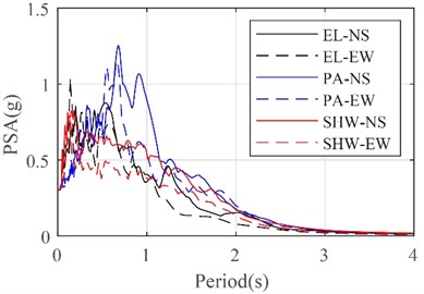
The two horizontal components of ground motions from the Imperial Valley earthquake at El Centro station in 1994 and from the California earthquake at the Pasadena station in 1952 were used, and artificial SHW2 ground motions were generated as the input waves. These ground motions were selected based on their spectral characteristics, and the fundamental period of the test model was 0.26 s. These sets of ground motions were also used by lots of studies for shaking table test [18, 19]. Fig. 5 illustrates the acceleration time histories of the three groups of ground motions. Fig. 6 presents a comparison among pseudo acceleration spectra (PSA) of these ground motions for the period from 0 to 4 Hz. This comparison demonstrates that the ground motions at the Pasadena station have highest PSAs at a long period of around 0.6-1.2 Hz, while the ground motions at the El Centro station have highest PSAs at a short period of around 0.1-0.2 Hz. The PSAs at the fundamental period of the structure are similar for all selected ground motions.
Table 3Seismic ground motion values for loading sequences
Loading sequence | Test condition | Intensity | Ground motions | Maximum acceleration (g) | |||
direction | direction | ||||||
Target | Measured | Target | Measured | ||||
1 | W1 | WN | 0.05 | 0.05 | |||
2 | EL-1s | 7 (frequent earthquake) | EL | 0.035 | 0.036 | ||
3 | EL-1d | 0.035 | 0.035 | 0.03 | 0.033 | ||
4 | PA-1s | PA | 0.035 | 0.033 | |||
5 | PA-1d | 0.035 | 0.032 | 0.03 | 0.026 | ||
6 | SHW2-1s | SHW2 | 0.035 | 0.023 | |||
7 | SHW2-1d | 0.035 | 0.028 | 0.03 | 0.024 | ||
8 | W2 | WN | 0.05 | 0.05 | |||
9 | EL-2s | 7 (basic earthquake) | EL | 0.1 | 0.101 | ||
10 | EL-2d | 0.1 | 0.105 | 0.085 | 0.079 | ||
11 | PA-2s | PA | 0.1 | 0.085 | |||
12 | PA-2d | 0.1 | 0.091 | 0.085 | 0.074 | ||
13 | SHW2-2s | SHW2 | 0.1 | 0.096 | |||
14 | SHW2-2d | 0.1 | 0.088 | 0.085 | 0.076 | ||
15 | W3 | WN | 0.05 | 0.05 | |||
16 | EL-3s | 7 (rare earthquake) | EL | 0.22 | 0.208 | ||
17 | EL-3d | 0.22 | 0.216 | 0.187 | 0.195 | ||
18 | PA-3s | PA | 0.22 | 0.184 | |||
19 | PA-3d | 0.22 | 0.231 | 0.187 | 0.176 | ||
20 | SHW2-3s | SHW2 | 0.22 | 0.181 | |||
21 | SHW2-3d | 0.22 | 0.182 | 0.187 | 0.154 | ||
22 | W4 | WN | 0.05 | 0.05 | |||
23 | EL-4s | 8 (rare earthquake) | EL | 0.4 | 0.375 | ||
24 | EL-4d | 0.4 | 0.416 | 0.34 | 0.354 | ||
25 | PA-4s | PA | 0.4 | 0.382 | |||
26 | PA-4d | 0.4 | 0.39 | 0.34 | 0.314 | ||
27 | SHW2-4s | SHW2 | 0.4 | 0.334 | |||
28 | SHW2-4d | 0.4 | 0.296 | 0.34 | 0.287 | ||
29 | W5 | WN | 0.05 | 0.05 | |||
30 | EL-5s | 9 (rare earthquake) | EL | 0.62 | 0.588 | ||
31 | EL-5d | 0.62 | 0.592 | 0.527 | 0.519 | ||
32 | PA-5s | PA | 0.62 | 0.574 | |||
33 | PA-5d | 0.62 | 0.563 | 0.527 | 0.51 | ||
34 | SHW2-5s | SHW2 | 0.62 | 0.492 | |||
35 | SHW2-5d | 0.62 | 0.406 | 0.527 | 0.422 | ||
36 | W6 | WN | 0.05 | 0.05 | |||
37 | EL-6s | Strong earthquake with 0.8 g | EL | 0.8 | 0.705 | ||
38 | EL-6d | 0.8 | 0.724 | 0.68 | 0.709 | ||
39 | PA-6s | PA | 0.8 | 0.764 | |||
40 | PA-6d | 0.8 | 0.722 | 0.68 | 0.671 | ||
41 | SHW2-6s | SHW2 | 0.8 | ||||
42 | SHW2-6d | 0.8 | 0.68 | ||||
43 | W7 | WN | 0.05 | 0.05 | |||
WN: White noise | |||||||
The loading conditions were divided into 6 loading groups according to seismic intensity from 0.035 g to 0.8 g. During every loading group, the scaled ground motions at the El Centro station, Pasadena station, and SHW2 artificial station were input in the direction and - directions in sequence. Specifically, the N-S components were input in the direction, while the E-W components were input in the direction. The ratio of peak ground acceleration in the and directions is 1:0.85. In addition, the test model was scanned by white noise between each seismic motion loading group to evaluate the damage of the structure by analyzing the natural frequency. Therefore, a total of 43 loading conditions was carried out in the present test. The specific loading sequence is shown in Table 3.
Fig. 5Acceleration time histories of input ground motions for shaking table test
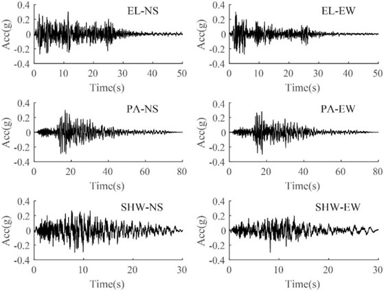
Fig. 6Pseudo acceleration spectra (PSA) of input ground motions for shaking table test
3. Test results and analysis
3.1. Observation of the experiment
The test model is carried out according to the loading conditions shown in Table 3. For the first three loading groups, no obvious crack and damage can be found on the steel frame and the precast concrete exterior wall panels because the peak ground acceleration (PGA) of input motions did not exceed 0.22 g. Also, the connections between wall panels and the frame were tight, and no obvious relative displacement can be found between wall panels and frame/panels. The test results reveal that the steel frame with the precast concrete exterior wall panel system is in elastic state under seismic intensity of 7. As the PGA increased to 0.4 g, a slight crack appeared on a wall panel at the second floor, which extended from the window corner to the top end of the wall. With the expectation of this crack, no other cracks were found in the panel wall systems. The connections between wall panels and the frame were still tight, and no obvious relative displacement between wall panels and frame/panels can be found.
Several vertical cracks on the outer side of wall panels at the second floor close to the window corner occurred as the PGA increased to 0.62 g. Slight shift can be found between the adjacent wall panels on the same floor, which was caused by the loosening of several bolts between the wall panels. The dynamic characteristic analysis also shows that the fundamental frequency of the structure decreased slightly under the loading ground with the seismic intensity of 9. The test results show that the structure is in elastic–plastic state with decreasing structural lateral stiffness.
As the PGA increased to 0.8 g, with extending of the cracks on wall panels at the second floor, vertical cracks can also be found on the wall panels at the first floor. At the same time, oblique and horizontal cracks appeared from the window corner to the periphery of the connections. The horizontal cracks are developed from the outside of the wall panel along the window corner and extend to the end of the wall panels. Also, a larger relative displacement between the adjacent wall panels at the same floors happened because of the sliding of connections. Finally, the steel bolts located at the bottom of some connections were loose and displaced. The dynamic characteristic analysis shows that the fundamental frequency and the lateral structure stiffness further decreased.
Fig. 7Structure damage
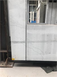
a) Cracks on wall panels
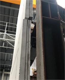
b) Shift between panels
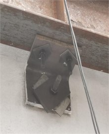
c) Loose bolt connections
3.2. Dynamic characteristics
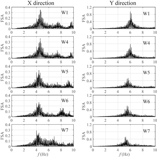
Based on the loading sequence, white noise with an amplitude of 0.05 g was subjected to the structure before and after the loading groups, to obtain the dynamic characteristics of the structural system. The natural frequencies of the test model under each loading condition were determined based on the Fourier spectra of the acceleration time history of the frames in the and directions.
Fig. 8 illustrates the Fourier spectra under the first and last four loading conditions in the presence of white noise. It is shown that the first and second order of the nature frequencies of the free field are 4.64 Hz and 6.0 Hz respectively. Under the three loading conditions with seismic intensity of 7, the natural frequencies of the structure model did not change obviously. It indicates that the structure was in elastic state without significant change of the lateral stiffness. After the loading group with seismic intensity of 8, the first two natural frequencies of the structure were reduced to 4.4 Hz and 5.63 Hz, with a decrease of 5.2 % and 6.2 % respectively.
As mentioned before, because some cracks had been appeared on the precast concrete wall panels under seismic loads with the seismic intensity of 8, the natural frequencies of the model decreased with the increase of the PGA of input earthquake ground motions, which indicates that the structural stiffness began to decrease. After all the seismic loads were activated, the first two natural frequencies of the structure were reduced to 4.0 Hz and 5.25 Hz, with a decrease of 13.8 % and 12.5 % corresponding to the free field test. The significant decrease of natural frequency may be influenced by loosing steel bolts at connections as subjected to ground motions with PGA = 0.8 g. Table 4 lists the first three natural frequencies detected under each white noise loading condition.
Table 4Natural frequency of structure
Loading condition | First-order (Hz) | Second-order (Hz) | Third-order (Hz) |
W1 | 4.64 | 6.00 | 11.90 |
W2 | 4.64 | 6.00 | 11.90 |
W3 | 4.64 | 6.00 | 11.91 |
W4 | 4.64 | 5.99 | 11.91 |
W5 | 4.40 | 5.63 | 11.31 |
W6 | 4.40 | 5.48 | 11.07 |
W7 | 4.00 | 5.25 | 10.89 |
Fig. 8Amplitude-frequency curves
3.3. Seismic response of inter-story drift ratio
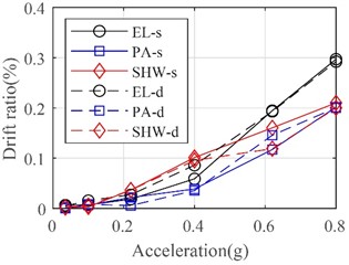
The time histories of the inter-story drift ratio of the frame in two directions under the bilateral inputs of El Centro ground motions with different PGA are shown in Fig. 9. It is clear that the drift ratios at the first floor are larger than those at the second floor in two lateral directions. With the increase of PGA, the maximum drift ratios also increase significantly. For instance, the average maximum drift ratios under rare earthquakes with the seismic intensity of 7, 8, and 9 are 0.06 %, 0.14 %, 0.23 % respectively. As the PGA increases to 0.8 g, the average maximum drift ratio increases to 0.28 %. Figs. 10 and 11 illustrate curves of maximum drift ratio subjected to different ground motions varying with PGA in both lateral directions. The largest drift ratios of the frame in the and directions are 0.43 % and 0.30 % respectively, which have been close to the limit value of elastic inter-story drift ratio according to the seismic design codes.
Fig. 9Time histories of inter-story drift ratio of frame subjected to bilateral El Centro ground motions
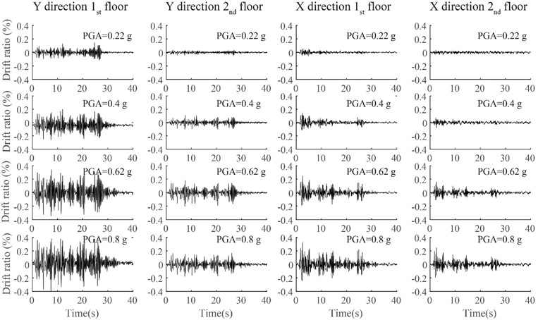
Fig. 10Maximum inter-story drift ratio in X direction
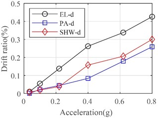
a) 1st floor
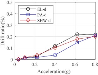
b) 2nd floor
Fig. 11Maximum inter-story drift ratio in Y direction
a) 1st floor
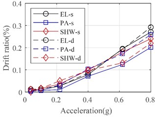
b) 2nd floor
3.4. Relative displacement between wall panels and frame
The relative displacement between wall panels and the frame were recorded by displacement transducers DB23~DB30. Fig. 12 shows the relative displacement on top and bottom ends of the W-1 wall panels. To account for the limited space available in this paper, only the experimental results for the second floor are discussed. It should be noted that the trends observed on the first floor are comparable. Results show that the measured relative displacement at the top end is generally greater than that at the bottom end, which is consistent with the arrangement of connections. With the increase of the PGA of seismic inputs, the relative displacement between wall panels and the frame increases gradually. For frequent earthquakes with the seismic intensity of 7, the relative displacement is less than ±1 mm, while it reaches to ±2 mm for the rare earthquake with the seismic intensity of 7. The largest relative displacement among all seismic loading conditions is approximately 12 mm. The relative displacement of the top end is basically consistent with the inter-story displacement of the steel frame, which indicates that the exterior wall panels can well adapt to the inter-story deformation of the main structure.
Fig. 12Relative displacement between wall panels and frame at second floor
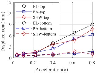
a) Wall panels along direction
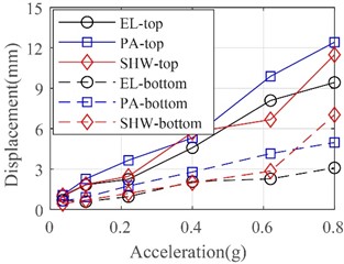
b) Wall panels along direction
3.5. Translational-type connection deformation
In this section, the authors present an analysis of the data obtained from a measuring point on top connections. Fig. 13 shows the in-plane relative displacement of the top connections of the W-1 wall panels at the second floor. It can be concluded that the sliding amount of the top connections of the exterior wall panel gradually increases with the increasing of the PGA of input ground motions. With the exception of a few measuring points, the sliding amounts of the top connections in the plane are not more than 1mm under the rare earthquakes with the seismic intensity of 7 degrees. For rare level 8 earthquake, the sliding value increases to some extent, but less than 5 mm. Moreover, subjected to rare level 9 earthquakes, the sliding amounts of the top connections further increase up to 8 mm.
Fig. 13In-plane relative displacement of top connections at second floor
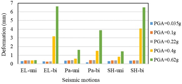
The results above mentioned demonstrate that the design of the top sliding connections can effectively realize the relative displacement between the precast concrete exterior wall panel and the main structure under earthquakes. Its advantage is to reduce the stress on the precast concrete exterior wall panel, and is consistent with the design concept. The translational-type connection is an efficient tool to protect the pre-casted concrete exterior panel in an elastic state even under a rare intensity of 9 degree without damage.
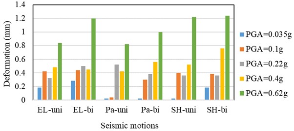
Fig. 14 illustrates the out-of-plane relative displacement of the top connection of the W-1 wall panels at the second floor under different seismic loads. The results indicate that, under rare earthquakes with the seismic intensity of 8 degrees, the out-of-plane relative displacement of top connection is less than 0.6 mm. For rare Level 9 earthquakes, the maximum relative displacement increases to 1.23 mm. These findings demonstrate that the top connections effectively restrain the out-of-plane deformation of the precast concrete exterior wall panel and reduce the risk of pull-off of the wall panels under strong earthquakes.
Fig. 14Out-of-plane relative displacement of top connections at second floor
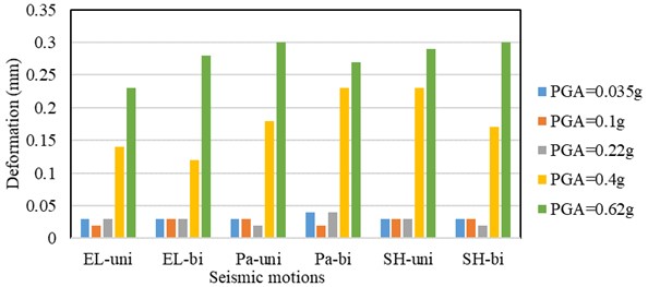
3.6. Diagonal deformation of the exterior wall panels
During the shaking table test, the diagonal relative deformation of the wall panel can be measured by the displacement transducers DB arranged along the diagonal direction of the external wall panels. Fig. 15 presents the diagonal deformation of the W-1 wall panels at the second floor. Results show that the maximum diagonal displacements of the wall panel are approximately 0.05 mm, 0.25 mm, and 0.3 mm under rare earthquakes with seismic intensity of 7, 8, and 9 degrees, respectively. It also demonstrates that the translational-type connection utilized in the present study can effectively adapt to the deformation of the steel frame. Deformation transferred from the frame to the wall panels is very low, which protect the wall panel without significant damage under large earthquakes.
Fig. 15Diagonal deformation of W-1 wall panels at second floor
3.7. Strain response analysis
The strain at the concrete surface of the exterior wall panel was measured using SB strain gauges, while the strain to the top and bottom connections was measured using SM and SN strain gauges, respectively. The strain gauges were placed at predetermined locations based on the standard parameters, and the theoretical strain limits for the C30 concrete were calculated to be 80 for tensile strength and –1760 for compressive strength. The strain to the top steel plate of the steel connector at the exterior wall panel was measured using strain gauges with the identification code SM, which were placed at the edge of the oblong hole of the top angle steel node. The strain to the bottom steel plate was measured using strain gauges with the identification code SN, which were placed on the bottom and side steel plates of the bottom angle steel node. The top and bottom angle steels were made of Q345B steel, and their theoretical yield strains were calculated as 1725.
Fig. 16 illustrates the maximum tensile and compressive strains in the lateral and vertical directions recorded from SB 17-24 on a W-1 concrete exterior wall panel at the second floor. It can be observed that the tensile and compressive strains remained at low levels before rare earthquakes with a seismic intensity of 7 degrees. However, the positive and negative maximum strains showed a rapidly increasing trend when the PGA exceeded 0.4 g. When the PGA reached 0.62 g (i.e., rare Level 9 earthquake), both strains recorded at the top and bottom ends of the wall panel in the lateral direction exceeded the tensile strength (tensile strain is 80). This indicates that the panel had cracks at the top and bottom ends, consistent with the observations described in Section 3.1.
Fig. 16Strains on W-1 concrete exterior wall panel at second floor
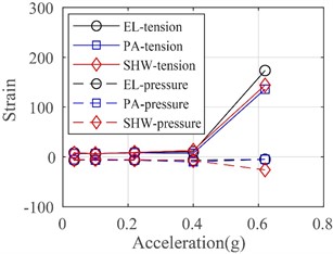
a) Top end in lateral direction
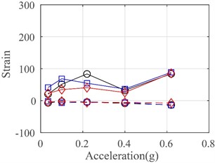
b) Top end in vertical direction
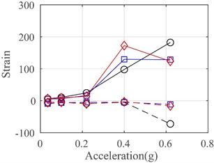
c) Bottom end in lateral direction
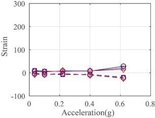
d) Bottom end in vertical direction
Fig. 17 presents the maximum tensile and compressive strains recorded from all strain gauges equipped at the wall panels, top connections, and bottom connections. After the entire test, the measured compressive strains were less than –500, only reaching 28 % of the compressive concrete strength. However, a vast number of measured tensile strains exceeded the tensile concrete strength, leading to cracks on the exterior wall panels. The maximum strain of the top and bottom connections was 790, demonstrating that all connections were in an elastic state even when subjected to a very large earthquake with a PGA of 0.62 g. The translational-type connections were safe enough to connect the full-scale exterior wall panels to the steel frame.
Fig. 17Strains on exterior wall panels and connections
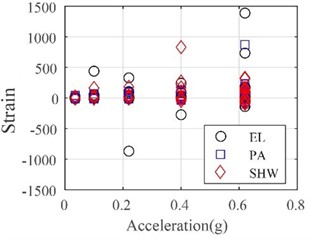
a) Exterior wall panels
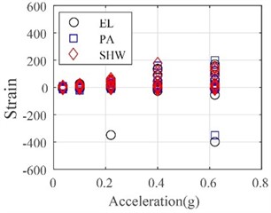
b) Top connections
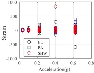
c) Bottom connections
4. Seismic performance evaluation
To further study the contribution of the translation-type connection on the seismic performance of the structures, 3D nonlinear finite element (FE) models were developed using the OpenSees platform [22]. Two FE models with different connection arrangements were established to compare the seismic response under 0.8 g bilateral El Centro ground motions. In Model A, the translation-type connection was employed as top connection on each wall panel, whereas the fixed connection was used as the bottom connection. In contrast, Model B utilized fixed connections for both the top and bottom connections. Apart from the connection arrangement, all other components for Model A and B are identical to those of the test model.
Because sections of the wall panel without windows exhibit significant stiffness, these areas are modeled with elastic beam-column elements. The nonlinear behavior of window frames of the wall, steel frames, and connections are taken into consideration in the structure modeling. Displacement-based beam-column element with fiber sections are used to describe the nonlinearity of window frames of the wall and steel frames. Concrete02 material is adopted to model the concrete. Mander’s confinement model [23] is used for unconfined or confined concrete fibers. Reinforcing Steel material is adopted for the steel reinforcement and Steel02 material is used for steel frames. The nonlinear behavior of fixed connection is modeled using uniaxial bilinear material. To account for the sliding effect of the translation-type connection, an elastic-plastic model-comprising a uniaxial bilinear zero-length element and an ElasticPPGap zero-length element-is used. The 3D nonlinear FE model of the structures and schematic diagram of various components are shown in Fig. 18. The mechanical properties of each component above-mentioned are listed in Table 5.
Fig. 19 presents a comparison of time histories for the drift ratio of the steel frame at the first floor in the direction, subjected to 0.8 g bilateral El Centro ground motions. The seismic response for Model A is very close to the results from the shaking table test. It indicates that the FE model developed in this study can capture the seismic response accurately. The maximum of drift ratio for Model B is 26 % that is lower than that of Model A. This demonstrates that the drift ratio of steel frame increases when the translation-type connection is employed as the top connection. In Model B, the fixed top connection increases the overall stiffness of the structure, therefore the drift ratio for Model B is smaller. Note that the maximum drift ratio for Model A is only 0.39 %, suggesting the steel frame remains within the elastic range when employing a translation-type connection.
Table 5Mechanical properties of structural components.
Components | Mechanical properties |
Steel frames | 345 Mpa, 2.1×10⁶ Mpa, 0.01 |
Window wall frames | Unconfined concrete: 21.0 Mpa, –0.002, 0, –0.006, 2.1 Mpa Confined concrete: 23.1 Mpa, –0.0032, 18.5 Mpa, –0.008, 2.1 Mpa Steel reinforcement: 335 Mpa, 420 Mpa, 2.1×10⁶ Mpa, 105 Mpa, 0.01, 0.132 |
Fixed connections | 57.0 kN, 0.5633 mm |
Translation-type connections | 35.7 kN, 0.3528 mm, 32.5 mm, 71.1 kN, 38.63 mm |
Fig. 183D nonlinear finite element model
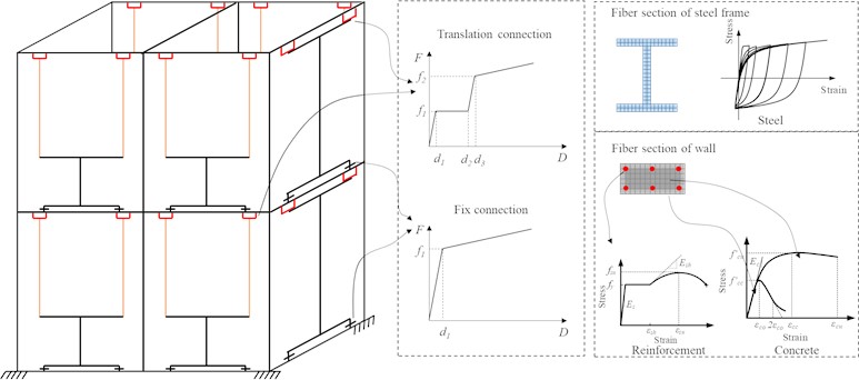
Fig. 19Comparison of inter-story drift ratio subjected to 0.8 g bilateral El Centro ground motions
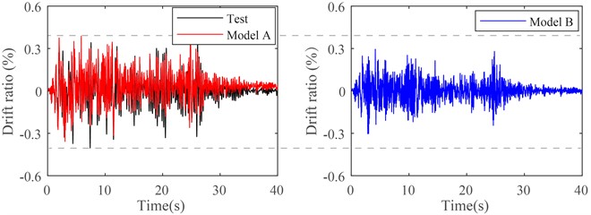
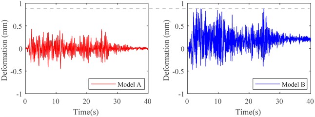
Fig. 20 illustrates time histories of wall-window frame for Model A and B at the first floor in the direction, subjected to 0.8 g bilateral El Centro ground motions. The figure shows that the maximum deformation of the wall-window frame for Model B exceeds Model A parameters by more than 200 %. Moreover, the wall-window frame for Model B exhibits approximately 0.2 mm residual deformation. It reveals that the wall panel for Model B has undergone plastic behavior. It is evident that the translation-type connection can effectively adapt to the deformation of the steel frame. It can sufficiently protect the wall panel, preventing significant damage even during major earthquakes.
Fig. 20Comparison of deformation of wall-window frame subjected to 0.8 g bilateral El Centro ground motions
5. Conclusions
Based on a practical project, a full-scale shaking table test was conducted for a steel frame with translational-type precast concrete exterior wall panels to investigate their deformation and seismic performance. The following conclusions were drawn from the test results:
1) The structural design of the top connection of the translational-type precast concrete exterior wall panel was found to be effective in ensuring the relative displacement between the wall panel and the main structure under strong earthquakes. The translational-type connection is an effective tool to adapt the deformation of the main structure for precast concrete exterior wall panels.
2) The connections between precast concrete exterior wall panels remained in an elastic state throughout the test, and exhibited good performance, which was found to be sufficient to meet the requirement that the wall panels do not fall off under strong earthquakes.
3) No collision was observed between the wall panels during the test, indicating that the design of the translation-type precast concrete exterior wall panel is reasonable and could effectively prevent from a collision damage during earthquakes.
References
-
S. Hu, W. Wang, and J. Yu, “Experimental and design strategy of precast exterior wall panels with damage-control function for steel buildings,” Journal of Building Engineering, Vol. 61, p. 105205, Dec. 2022, https://doi.org/10.1016/j.jobe.2022.105205
-
D. Mitchell, R. H. Devall, M. Saatcioglu, R. Simpson, R. Tinawi, and R. Tremblay, “Damage to concrete structures due to the 1994 Northridge earthquake,” Canadian Journal of Civil Engineering, Vol. 22, No. 2, pp. 361–377, Apr. 1995, https://doi.org/10.1139/l95-047
-
B. Zhou, Q. Si, L. Zong, and B. Wang, “Seismic performance analysis of steel frames with FCP composite external wall,” Structures, Vol. 39, pp. 86–97, May 2022, https://doi.org/10.1016/j.istruc.2022.02.076
-
C. Zhang, K. Ding, and S. He, “Seismic performance of panel connectors with steel frame based on autoclaved lightweight concrete (ALC),” Buildings, Vol. 12, No. 3, p. 372, Mar. 2022, https://doi.org/10.3390/buildings12030372
-
H. Hou et al., “Low-rise steel moment frames with energy-dissipating exterior walls: computer modelling and seismic performance assessment,” Engineering Structures, Vol. 256, p. 113971, Apr. 2022, https://doi.org/10.1016/j.engstruct.2022.113971
-
G. Li and C. Wang, “The hysteretic behavior of steel frames with ALC out-hung and infilled wall,” (in Chinese), Steel Construction, Vol. 20, No. 1, pp. 52–56, 2005, https://doi.org/10.13206/j.gjg200501015
-
H. Tian and Y. Chen, “Experimental research and finite element analysis on lateral shearing behavior of ALC spliced connection wallboard,” (in Chinese), Journal of Building Structures, Vol. 30, No. 2, pp. 85–91, 2009.
-
J. Hu, F. Xu, D. Du D., S. Wang, and W. Li, “Experimental study on shaking table test of full-scale steel frame with embedded autoclaved lightweight concrete wall panels,” (in Chinese), Journal of Building Structures, Vol. 39, No. 6, pp. 141–148, 2018, https://doi.org/10.14006/j.jzjgxb.2018.06.015
-
S. Wang, L. Zhuang, D. Du, and W. Li, “Full-scale shaking table tests on frame structure with new sip filling wallboard,” (in Chinese), Vibration and shock, Vol. 34, No. 18, pp. 100–105, 2015.
-
W. Qiao, J. Kang, D. Wang, J. Yuan, and Z. Wang, “Shaking table test on insulated sandwich concrete wall building structure,” Journal of Building Engineering, Vol. 37, p. 102165, May 2021, https://doi.org/10.1016/j.jobe.2021.102165
-
R. Lameiras, J. A. O. Barros, I. B. Valente, E. Poletti, M. Azevedo, and M. Azenha, “Seismic behaviour of precast sandwich wall panels of steel fibre reinforced concrete layers and fibre reinforced polymer connectors,” Engineering Structures, Vol. 237, p. 112149, Jun. 2021, https://doi.org/10.1016/j.engstruct.2021.112149
-
H. Guo, L. Sun, Y. Liu, J. Hao, and Z. Wang, “Experimental study on seismic behavior of flexible steel frame with recycle concrete exterior wall,” (in Chinese), Journal of Building Structures, Vol. 38, No. 2, pp. 63–73, 2017.
-
C. Zhang, Z. Li, W. Huang, X. Deng, and J. Gao, “Seismic performance of semi-rigid steel frame infilled with prefabricated damping wall panels,” Journal of Constructional Steel Research, Vol. 184, p. 106797, Sep. 2021, https://doi.org/10.1016/j.jcsr.2021.106797
-
H. Hou et al., “Shake table tests of exterior sandwich composite walls flexibly connected to full-scale steel braced frames,” (in Chinese), Journal of Building Structures, Vol. 40, No. 12, pp. 21–31, 2019, https://doi.org/10.14006/j.jzjgxb.2018.0297
-
T. N. Dao and J. W. van de Lindt, “Seismic performance of an innovative light-frame cold-formed steel frame for midrise construction,” Journal of Structural Engineering, Vol. 139, No. 5, pp. 837–848, May 2013, https://doi.org/10.1061/(asce)st.1943-541x.0000683
-
W. Wang, Y. Chen, Y. Chen, and H. Hou, “Full-scale shaking table test of a floor-by-floor assembled steel braced frame with external pc composite wall panel,” (in Chinese), Journal of Building Structures, Vol. 40, No. 2, pp. 88–97, 2019, https://doi.org/10.14006/j.jzjgxb.2019.02.007
-
X. Chong, L. Bin, L. Xie, X. Wang, and X. Chen, “Investigation on the collaborative seismic performance of prefabricated frame structures with energy dissipating cladding panels,” (in Chinese), Engineering Mechanics, Vol. 38, No. 6, pp. 209–217, 2021, https://doi.org/10.6052/j.issn.1000-4750.2020.07.0471
-
S. Longjam and K. Shirai, “Numerical investigation of earthquake response reduction effects by negative stiffness connection for adjacent building structures,” Structures, Vol. 38, pp. 672–688, Apr. 2022, https://doi.org/10.1016/j.istruc.2022.01.078
-
H. Jiang, X. Zhao, and H. Miao, “Design method and mechanical behavior analysis of translational precast concrete facade wall panel connecting joints,” (in Chinese), Building Structures, Vol. 51, No. 5, pp. 41–47, 2021.
-
X. Lu, Y. Zhou, and W. Lu, “Shaking table model test and numerical analysis of a complex high-rise building,” The Structural Design of Tall and Special Buildings, Vol. 16, No. 2, pp. 131–164, Jun. 2007, https://doi.org/10.1002/tal.302
-
Q. Xu, H. Zhang, Q. Liu, and L. Wang, “Seismic analysis on reinforced concrete group silos through shaking table tests,” Structural Concrete, Vol. 22, No. 3, pp. 1285–1296, Jun. 2021, https://doi.org/10.1002/suco.202000207
-
S. Mazzoni, F. Mckenna, M. H. Scott, and G. L. Fenves, “OpenSees command language manual,” Pacific Earthquake Engineering Research (PEER) Center, 2006.
-
J. B. Mander, M. J. N. Priestley, and R. Park, “Theoretical Stress‐Strain Model for Confined Concrete,” Journal of Structural Engineering, Vol. 114, No. 8, pp. 1804–1826, Sep. 1988, https://doi.org/10.1061/(asce)0733-9445(1988)114:8(1804)
About this article

The present study is financially supported from the Joint Funds of National Natural Science Foundation of China (Grant No. U1934205). The authors would like to thank Dr. Linpu Du for his helpful discussion. Finally, the authors wish to thank two anonymous reviewers for their constructive comments and suggestions that led to improvements in the manuscript.
The datasets generated during and/or analyzed during the current study are available from the corresponding author on reasonable request.
Jianhua Shi: investigation, resources, validation, writing – original draft preparation. Fan Zhang: methodology, supervision, visualization, writing – review and editing. Xuefei Zhao: formal analysis, data curation, resource. Jianbao Li: formal analysis, data curation. Wei Tian: supervision, conceptualization. Jingquan Wang: supervision, conceptualization, funding acquisition.
The authors declare that they have no conflict of interest.
