Abstract
This paper investigates the stress-strain behavior of rail fastening systems in railway turnouts subjected to non-uniform stiffness distribution and cyclic axial wheel loading. Unlike conventional track sections, turnout fastening units exhibit structural asymmetry and complex load transfer mechanisms that significantly influence stress evolution and deformation response. A three-dimensional finite element model was developed to analyze the behavior of switch slide chairs under loading applied separately to the stock rail and the switch rail. The analysis determined maximum deflections of 4 and 5 mm for the stock-rail and switch-rail loading cases, respectively, and identified critical stress states from +200 to –433 MPa that may contribute to fatigue-related damage under repeated service conditions. The results demonstrate that under-rail pad stiffness substantially affects stress redistribution and the durability of fastening nodes. Based on these findings, recommendations are proposed for refining stiffness parameters to enhance the reliability and service life of railway turnouts.
Highlights
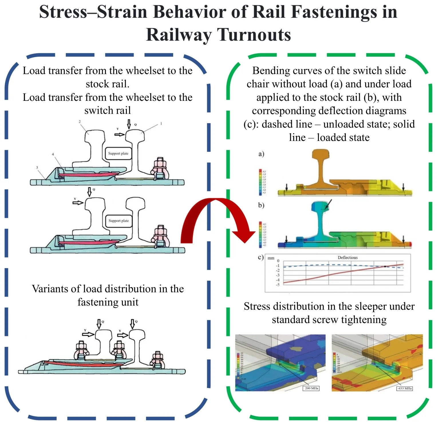
- Load transfer from the wheelset to the stock rail. Load transfer from the wheelset to the switch rail
- Variants of load distribution in the fastening unit
- Bending curves of the switch slide chair without load (a) and under load applied to the stock rail (b), with corresponding deflection diagrams (c): dashed line – unloaded state; solid line – loaded state
- Stress distribution in the sleeper under standard screw tightening
1. Introduction
Railway turnouts are critical elements of railway infrastructure that ensure safe redirection of rolling stock. Due to their complex geometry, rail profile discontinuities, and the presence of switch rails and crossings, turnouts differ significantly from conventional track sections in terms of load transfer mechanisms and stiffness distribution along the track structure [1-3]. As a result, fastening elements in turnout zones operate under specific mechanical and vibration conditions that affect their deformation behavior and durability.
From a vibroengineering perspective, turnout areas represent zones of increased dynamic impact. The passage of wheelsets through switches and crossings generates cyclic stresses caused by axle loads and structural irregularities of the turnout [4-8]. Even within a quasi-static formulation, axial wheel loads remain the dominant operational factor governing deformation and fatigue accumulation in fastening elements.
Although previous studies have investigated the interaction between rolling stock and rail fastening systems, focusing on track vibration behavior and stiffness characteristics [1, 4-8], the stress–strain state of turnout fastening units under axial loading remains insufficiently studied. Recent international studies have emphasized the importance of turnout stiffness variation, nonlinear finite element modeling, and rail-pad parameter sensitivity for evaluating local stresses in fastening zones [6, 9, 10, 11]. In particular, limited attention has been paid to the structural asymmetry of switch slide chairs and the specific load transfer mechanisms between stock and switch rails [1, 4, 12, 13].
This study aims to analyze the stress–strain behavior of rail fastenings in a railway turnout under axial loading using a three-dimensional finite element model. The research evaluates deformation patterns, stress distribution, and the influence of under-rail pad stiffness on the mechanical behavior of fastening units. The obtained results provide quantitative assessment of alternating stress states and contribute to improving stiffness selection and durability-oriented design of turnout fastening systems.
2. Materials and methods
2.1. Features of rail fastenings in railway turnouts
Railway turnouts differ from conventional track sections due to their complex geometry and the presence of switch and crossing elements. These structural characteristics necessitate the use of specialized rail fastening systems adapted to varying load transfer mechanisms within the turnout [1, 3, 4, 12].
A railway turnout consists of several principal components, including the switch rail, stock (frame) rail, turnout tracks, and the crossing. Each element possesses distinct structural features and functional roles, requiring the application of different types of intermediate rail fastenings.
To investigate the stress-strain state of rail fastening units in railway turnouts, a three-dimensional finite element model was developed. The analysis was performed using the finite element method (FEM) to simulate stress distribution and deformation behavior of fastening components subjected to axial wheel loading. Numerical modeling software was employed to represent switch slide chairs, elastic pads, fastening clips, and associated structural elements, enabling realistic simulation of structural interaction under operational conditions [4, 13, 14].
The model was formulated in a quasi-static setting because the objective was to compare local deformation and stress redistribution under two representative operational loading cases. The axial wheel load was applied as a distributed vertical load on the rail head in separate stock-rail and switch-rail configurations. Contact behavior between the fastening components was represented within the adopted linear-elastic idealization, while the mesh was locally refined in the central zone of the slide chair where peak stresses were expected.
The main input parameters adopted in the model are summarized in Table 1.
Table 1Input parameters of the finite element model
Parameter | Symbol | Value | Unit | Description |
Static stiffness of under-rail pad | 30 | kN/mm | Linear elastic stiffness of pad | |
Mounting clamping force | 10 | kN | Preload applied by fastening clips | |
Axial wheel load | Applied load | kN | Distributed load applied to rail head | |
Material model (steel components) | – | Linear elastic | – | Elastic behavior assumed |
Material model (elastic pad) | – | Linear elastic | – | No plasticity considered |
Boundary condition (baseplate) | – | Fixed translations | – | Conservative attachment to sleeper support |
The analysis was carried out in a quasi-static formulation assuming linear elastic material behavior for steel components and elastic pads. Geometric nonlinearity and material plasticity were not considered. The baseplate was constrained in translational degrees of freedom to simulate fastening attachment to the sleeper support, while axial wheel load was applied to the rail head. Loading was modeled separately for stock rail and switch rail configurations.
Full translational fixation of the baseplate was adopted as a simplifying and conservative boundary condition for the present local stress analysis. In actual track conditions, the compliance of the pad-sleeper system may reduce local stress peaks; however, the adopted assumption makes it possible to compare the relative response of the fastening node under the two loading scenarios on a consistent basis.
The loading scenarios considered in the numerical model are presented in Table 2.
Table 2Loading configurations considered in the model
Loading case | Load application point | Load transfer path | Deformation pattern | Engineering significance |
Case 1 | Stock (frame) rail | Through stock rail to slide chair | Predominantly downward deflection | Represents open switch configuration |
Case 2 | Switch rail (blade) | Through switch blade and bearing plate | Central bending of slide chair | Represents closed (clamped) switch configuration |
The finite element mesh consisted of three-dimensional solid elements with local refinement in regions of expected stress concentration, particularly in the central part of the switch slide chair. Mesh density was selected to ensure stable stress distribution without numerical instability.
In the switch zone, pads with a cushioning element under the switch blade (referred to as switch slide chairs) are typically used. Depending on the fastening type (flexible or rotating), root connections may also be implemented. Switch slide chairs are characterized by geometric asymmetry, resulting in non-uniform deformation under elastic fastening conditions.
In the root area of the switch rail, vertical and horizontal load transfer mechanisms become particularly significant (see Figs. 1 and 2). When the switch rail is open, vertical loads are primarily transmitted to the stock rail; when the switch rail is closed (clamped), vertical loads are transferred through the switch blade. Horizontal forces are transmitted from the switch blade to the neck of the stock rail via a bearing plate.
Fig. 1Load transfer from the wheelset to the stock rail: 1 – stock (running) rail; 2 – switch rail; 3 – slide chair; 4 – elastic pad
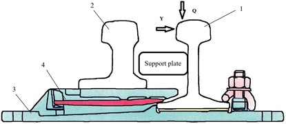
Fig. 2Load transfer from the wheelset to the switch rail
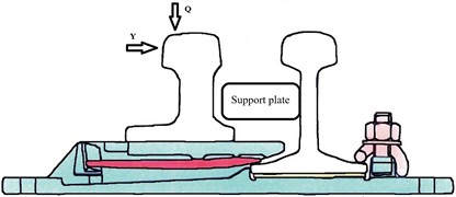
Fig. 3Variants of load distribution in the fastening unit
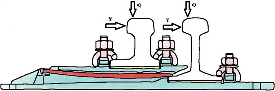
In addition, the stock rail and the root of the switch rail are fastened to the baseplate using clips or clamping terminals (see Fig. 3). This fastening configuration introduces additional constraints that influence pad deformation and stress redistribution within the fastening assembly.
2.2. Results and discussion
The numerical analysis demonstrates that the conventional criterion of equal static and dynamic stiffness at the support point, typically applied to intermediate fastenings of conventional track sections, is not directly applicable to turnout fastening systems. Structural asymmetry of the switch slide chair and distinct load transfer paths lead to fundamentally different stiffness behavior under alternative loading configurations. Consequently, the static stiffness coefficient () cannot be reliably evaluated for turnout nodes using simplified assumptions developed for standard track conditions.
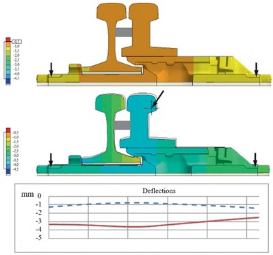
Finite element simulations were performed for two loading cases: axial load applied to the stock rail and axial load applied to the switch rail (see Figs. 4 and 5). The influence of pad elasticity was also considered. The principal comparative results are summarized in Table 3.
For clarity, Figs. 4 and 5 compare the unloaded and loaded configurations of the slide chair for the stock-rail and switch-rail loading cases, respectively; in both figures, the dashed line denotes the unloaded state and the solid line denotes the loaded state.
Table 3Comparative results of deformation and stress analysis
Parameter | Stock rail loading | Switch rail loading |
Maximum deflection (mm) | 4 | 5 |
Dominant deformation mode | Downward displacement | Central bending |
Maximum stress location | Edge zone | Central zone |
Stress range (MPa) | Up to +200 | Down to –433 |
Under stock rail loading, the slide chair exhibits predominantly downward displacement, corresponding to compression-dominated structural response. In contrast, loading applied to the switch rail produces bending deformation concentrated in the central region, resulting in greater structural flexibility and approximately 20-25 % higher maximum deflection compared with the stock rail case.
The stress distribution patterns further confirm the asymmetric mechanical behavior of the fastening node. Stock rail loading generates tensile stresses primarily in edge regions, whereas switch rail loading leads to pronounced stress concentration in the central part of the slide chair. The reported values from +200 MPa to –433 MPa correspond to critical stress states obtained in the most unfavorable zones under different loading scenarios; therefore, they characterize a potential alternation of the stress state in service rather than a directly simulated fully reversed cycle at one identical material point. According to the present numerical analysis, such stress reversal conditions may contribute to fatigue-related damage under repeated service loading.
Redistribution of forces within the fastening assembly leads to non-uniform stiffness at the pad–sleeper interface. The results show that stiffness evaluation in turnout systems should be based on localized stress–strain analysis rather than a single equivalent stiffness coefficient. Under switch rail loading, bending-dominated deformation reduces the effective stiffness of the slide chair, whereas stock rail loading produces a more constrained displacement response.
Additional variability may occur in curved turnouts due to alternative fastening configurations, including systems without elastic pads on concrete sleepers or slab track. In crossing zones, fastening behavior also depends on crossing geometry, while check rails introduce additional forces acting on bearing pads. Excessive pad compliance may increase deformation amplitudes and accelerate fatigue-related damage under repeated loading; therefore, excessively low pad stiffness should be avoided in locations where bending-dominated response of the slide chair is expected.
The analysis confirms that the stress–strain behavior of turnout fastening systems differs from that of conventional track sections due to structural asymmetry and specific load transfer mechanisms. Numerical modeling shows that stresses in the switch slide chairs range from +200 MPa to –433 MPa (Fig. 6), indicating possible alternation of stress states during long-term operation. Stock rail loading primarily causes downward deflection, whereas switch rail loading results in localized bending concentrated in the central region.
Fig. 4Bending curves of the switch slide chair without load (upper) and under load applied to the stock rail (middle), with corresponding deflection diagrams (lower): dashed line – unloaded state; solid line – loaded state
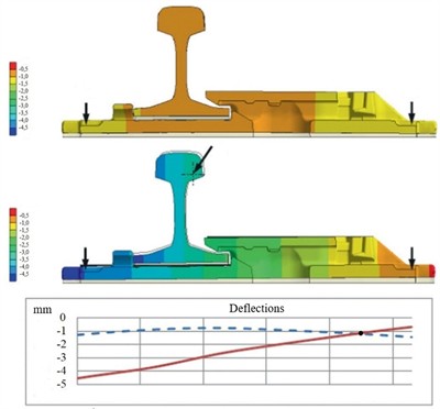
Fig. 5Bending curves of the switch slide chair without load (upper) and under load applied to the switch rail (middle), with corresponding deflection diagrams (lower): dashed line – unloaded state; solid line – loaded state
Comparison with previously published results [1, 3, 4, 15, 16] shows that the obtained stress levels are consistent with reported values. However, the present study additionally accounts for asymmetric load distribution and variation in pad elasticity, which enables a more detailed assessment of local stiffness and stress redistribution within the fastening unit. These findings support earlier conclusions regarding the necessity of refining stiffness parameters of under-rail pads to improve turnout durability.
Fig. 6Switch slide chair under stress: a) under mounting preload only; b) under axial wheel load applied to the rail
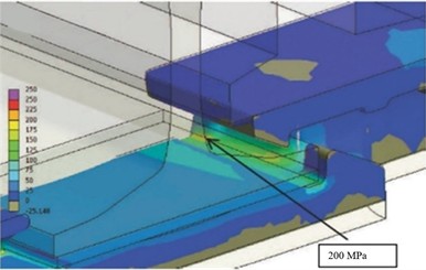
a)
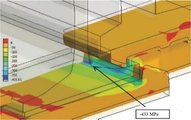
b)
3. Conclusions
1) The study demonstrates that the stress-strain behavior of rail fastening systems in railway turnouts differs fundamentally from that of conventional track sections due to geometric asymmetry and specific load transfer mechanisms inherent to turnout structures. Under axial wheel loading, switch slide chairs exhibit asymmetric deformation patterns, with maximum deflections of 4 mm for stock-rail loading and 5 mm for switch-rail loading; thus, the latter case produces approximately 20-25 % greater deformation.
2) Three-dimensional finite element analysis enabled quantitative assessment of deformation and stress redistribution within the fastening assembly. Critical stress states ranging from +200 MPa to –433 MPa were identified in the most unfavorable zones, indicating possible stress reversal conditions that, according to the present numerical analysis, may contribute to fatigue-related damage under repeated service loading.
3) The results confirm that stiffness characteristics of turnout fastening nodes are governed not only by material properties but also by structural configuration, loading scenario, and pad elasticity. Therefore, stiffness evaluation in turnout systems should be based on localized stress-strain analysis rather than simplified global coefficients. From a practical standpoint, excessively low under-rail pad stiffness should be avoided because increased compliance intensifies bending-dominated deformation in the central part of the slide chair and may reduce the durability and operational reliability of railway turnouts.
References
-
E. S. Ashpiz et al., “Railway Track,” (in Russian), Educational and Methodological Center for Railway Transport Education, Moscow, Russia, 2021.
-
“Rules for the technical operation of railways of the Russian federation,” (in Russian), Ministry of Transport of the Russian Federation, Moscow, Russia, 2022.
-
B. E. Glyuzberg and V. V. Korolev, “Generations of turnouts,” (in Russian), Track and Track Facilities, No. 12, pp. 21–24, 2021.
-
B. E. Glyuzberg, V. V. Korolev, and I. V. Shishkina, “Technical requirements for sixth-generation turnouts,” (in Russian), Track and Track Facilities, No. 7, pp. 21–24, 2022.
-
A. Y. Kogan, V. F. Baraboshin, and V. M. Gavrilov, “Vibration of a five-layer beam on an elastic foundation under moving dynamic load,” (in Russian), Russia: Novosibirsk, 1986, pp. 33–43.
-
J. Xu, P. Wang, X. Ma, Y. Gao, and R. Chen, “Stiffness characteristics of high-speed railway turnout and the effect on the dynamic train-turnout interaction,” Shock and Vibration, Vol. 2016, pp. 1–14, Jan. 2016, https://doi.org/10.1155/2016/1258681
-
V. V. Vinogradov, A. M. Nikonov, and T. G. Yakovleva, Design and Calculation of Railway Track. Moscow, Russia: Marshrut, 2003.
-
“Method for assessing the impact of rolling stock on the track in terms of reliability assurance,” (in Russian), JSC “Russian Railways” Moscow, Russia, 2017.
-
J. Sae Siew, O. Mirza, and S. Kaewunruen, “Nonlinear finite element modelling of railway turnout system considering bearer/sleeper-ballast interaction,” Journal of Structures, Vol. 2015, pp. 1–11, Apr. 2015, https://doi.org/10.1155/2015/598562
-
K. S. Lesov and K. G. A. Rustamovich, “Diagnostic tool for indirect determination of clip pressure in pandrol fastclip fastening,” Universum: Technical Sciences, No. 5-4(98), pp. 54–56, 2022.
-
M. Oregui, A. Núñez, R. Dollevoet, and Z. Li, “Sensitivity analysis of railpad parameters on vertical railway track dynamics,” Journal of Engineering Mechanics, Vol. 143, No. 5, p. 04017011, May 2017, https://doi.org/10.1061/(asce)em.1943-7889.0001207
-
A. M. Zhangabylova, I. S. Bondar, M. Y. Kvashnin, A. M. Abyazova, and A. D. Konysbay, “Analysis of the performance of intermediate rail fasteners under operational load,” Bulletin of KazATC, No. 4(133), 2024.
-
T. A. Dung and D. X. Quy, “Experimental study on in-plane stiffness of track in a turnout of the railway in Vietnam,” The Open Construction and Building Technology Journal, Vol. 17, No. 1, 2023, https://doi.org/10.2174/0118748368274755231128111815
-
“Rail fastening pads for railway track,” (in Russian), Standartinform, Moscow, Russia, GOST 34078-2017, 2017.
-
“Rod-type spring clips for rail fastening,” (in Russian), Standartinform, Moscow, Russia, GOST 33186-2014, 2014.
-
A. V. Petrov, “Elastic rail pads – a fundamental part of ballastless track,” in Implementation of Modern Structures and Advanced Technologies in Track Facilities, Vol. 14, 2019, pp. 87–93.
About this article

The authors have not disclosed any funding.
The datasets generated during and/or analyzed during the current study are available from the corresponding author on reasonable request.
The authors declare that they have no conflict of interest.
