Abstract
Due to the widespread failure of subway cars, the Tashkent Metropolitan Company requires the development of a new method for upgrading the frames of multiple unit rolling stock bogies scheduled for major repairs. This method improves dynamic performance and increases strength and reliability (in particular, for subway car bogies). This article presents a dynamic calculation of a modernized design for a multiple unit metro bogie, substantiating its dynamic and strength parameters. Numerical studies were conducted using the MATHCAD 15 programming environment. The calculations performed allow us to identify the bogie components that require reinforcement. The design presented in this article is protected by Patent of the Republic of Uzbekistan for Invention No. IAP 06498 [1].
1. Introduction
According to the International Union of Public Transport, a metro is a predominantly intracity passenger transport system with its own railway lines, completely separated from vehicular and pedestrian traffic. The first metro in the world was the London Metro, opened in 1863 and electrified in 1890. The Beijing Metro is the busiest. The Shanghai Metro leads in terms of line length and number of stations, the New York Metro leads in terms of number of lines, and the Saint Petersburg Metro leads in terms of average station depth. In the world, the task of assessing and forecasting the resource of electric trains of the metro has been considered in many scientific works and is relevant at the present time. This is due to both economic and organizational reasons caused by the aging of the fleet of electric rolling stock and the desire to prevent dangerous destruction, based on the standardized parameters of the resource, safety and risks under strength conditions.
However, one of the specific features of metro systems is the higher reliability requirements for rolling stock compared to surface transportation, due to the tunnel nature of train travel with minimal headways and poor track infrastructure. In other words, any failure – that is, an event that disrupts the functionality of a metro car – can lead to disruption of the schedule for one line, and, in severe cases, disrupt the entire metro system and the modern city's transportation system.
Thus, the most important characteristics of metro rolling stock are reliability indicators, primarily failure-free operation. Currently, in metro systems in Uzbekistan and neighboring countries operating Russian-made electric trains, one of the least reliable components in the design of older-generation cars is the bogie frames.
Currently, one of the least reliable components in the design of the Tashkent Metro’s 81-717/714 series electric rolling stock and its modifications is the bogie frames. The manufacturer specifies a service life of 16 years for the spindle bogie frames of this rolling stock, while the service life of the guided bogie frames is 2.5 million kilometers (approximately 25 years). However, given operational practices (the cars operate on a single route) and maintenance (they are serviced at their Home Depot), as well as the absence of dangerous failures in the bogie frame metalwork of the metro cars, there is reason to believe that the service life of their supporting structures has not been exhausted.
In light of the above, there is an urgent need to determine the technical condition of existing bogie frame structures after extended use, establish their strength compliance with current regulatory requirements, and numerically assess their remaining service life. This work included an analysis of operational damage to the metal structures of Tashkent Metro bogie frames for cars of the 81-717.5, 81-714.5, and 81-717 and 81-714 series, which have exceeded their manufacturer-specified service life.
In this regard, conducting scientific research to improve the methodology for calculating the residual life of the frames of metro electric train bogies at high speeds is relevant both for the Republic of Uzbekistan and for the entire international community, where the metro is widely deployed.
Despite years of research, experience, and improvements in running gear design, potential directions for further development continue to be identified [7-14].
In Uzbekistan, the problem of optimizing the operation of wheels and rails by reducing contact stresses during the dynamic interaction of wheel pairs of rolling stock, as well as the development of methods for calculating the dynamic strength of frame structures of locomotives of complex configuration and methods for calculating the resource for transport engineering were studied by Academician of the Academy of Sciences of the Republic of Uzbekistan, Professor Glushchenko A.D., Professors Fayzibaev Sh.S., Khromova G.A., Shermukhamedov A.A., Rakhimov R.V., Khamidov O.R., Zainutdinov N.S., Radjibayev D.O. and their students [15-21].
Under the influence of cyclic dynamic loads, the strength properties of the metal of the parts and structures of the undercarriage of electric trains (bogie frames, main frames and bodies, parts of wheel pairs, etc.) degrade, their fatigue resistance decreases, the yield strength and brittleness of the material increase, which can lead to their destruction. Therefore, conducting scientific research in this area with the development of a method for calculating the residual life of bogie frames of electric trains with an assessment of their reliability for the conditions of the Republic of Uzbekistan is a relevant topic.
2. Methodology
The research methodology includes the compilation of mathematical models for optimizing the spring suspension system of a high-speed electric train with improved elastic-dissipative suspension properties and justification of dynamic strength parameters. Standard methods of resistance of materials, theory of elasticity, theory of vibrations, dynamics and strength of machines using computers were used for research. Numerical studies were performed in the Mathcad 15 programming environment using numerical methods: boundary element method, piecewise linear approximation and iteration method.
This article is devoted to the development of a new method for assessing the reliability indicators of the frames of subway electric train bogies based on the results of diagnostics; numerical studies were performed in the MATHCAD 15 programming environment.
The novelty of this topic is the improvement of the methodology for calculating the residual life of electric train bogie frames at high speeds for the conditions of the Republic of Uzbekistan.
As a result, a scientific substantiation of methods for increasing the reliability and durability of electric train bogie frames will be conducted using a newly developed mathematical model for calculating the residual life of electric train bogie frames at high speeds for the conditions of the Republic of Uzbekistan.
3. Theoretical and practical results
The stresses that arise in the parts of the subway car bogie frames during operation are in most cases variable in time, and they are often random functions of time. If the level of variable stresses exceeds a certain limit, then a process of gradual accumulation of damage occurs in the material of the part, leading to the formation of a crack, its development and the final destruction of the part. This process is conventionally called metal fatigue, and the corresponding destruction is called fatigue [2, 3].
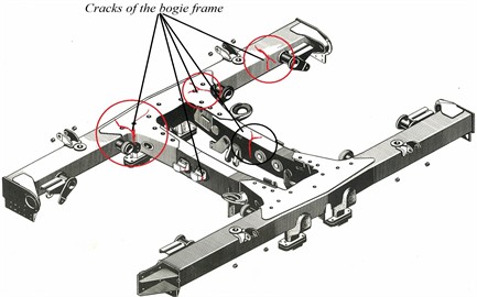
The Department of Operation of Subway Cars of JSC “Uzbekistan Railways” in Tashkent has identified a significant number of fatigue cracks, despite their repair according to the instruction CT 336, which significantly weakens the most dangerous sections. Figure 1 shows a photograph of a subway car bogie of modification 81-717/714 with fatigue cracks in the bogie frame after 30 years of operation.
This circumstance has caused the need for further improvement of dynamic characteristics and increase in strength, reliability and failure-free operation, as well as justification of the frequency of non-destructive testing during diagnostics [4,5].
The Tashkent metro lines use cars of the following models: 81-717, 81-714, 81-717.5, 81-714-5. Cars of the 81-717.5 and 81-714.5 models are a modification of cars 81-717 and 81-714.
Fig. 1The bogie frame of the 81-717/714 series subway wagon with fatigue cracks
The modernized subway car body frame is made of welded channel-shaped beams. The basic unit of the bogie, on which all the undercarriage equipment is mounted, is a welded H-shaped frame. The frame consists of side chords and two cross beams. The side chords of the frame are a channel 180 mm high with a horizontal shelf width of 70 mm. The chords are made of separate parts (beams), which are butt-welded using electric arc welding. The side chords have oval holes for welding the outer skin of the body walls.
When calculating the bogie frame of a multi-car subway car, it is considered as a spatial rod system, numerical studies were carried out in the programming environment MATHCAD 15.
The calculation of the dynamic strength of the subway car bogie frame is carried out in the following order:
1) The values of the forces acting on the frame are determined and the main design loading schemes are compiled, which are the initial ones for all further calculations.
2) The main design loading schemes are divided into simpler auxiliary ones: vertical and horizontal, symmetrical and antisymmetrical loads are considered separately.
3) The auxiliary and main loading schemes of the subway car bogie frame are calculated.
4) The values of normal stresses are determined for the main loading schemes of the subway car bogie frame. The values of shear stresses are not determined in the calculation, due to their insignificant value. It should also be noted that the places (grain) of maximum shear and maximum normal stresses do not coincide.
5) The stresses in the design sections are summed up from the most unfavorable and possible combinations of loads in operation: 5.1. traction on a straight line; 5.2. braking on a straight line. The stress state of the subway car bogie frame is characterized by the values of the maximum total stresses from the above-listed operating modes of the subway car, as well as the values of stresses acting when rolling out the wheel pairs (when lifting the subway car by the bogies).
We have conducted a comparative analysis of the stress-strain state of the subway car bogie frame (with and without reinforcing pads) with the calculation of fatigue strength coefficients, on the basis of which it is possible to predict the possible further useful life of the mechanical part of the subway car (specifically, for the two-axle frame of the modernized bogie of subway cars mod. 81-717/714 – Fig. 1).
The design sections for the two-axle frame of the modernized bogie of metro cars mod. 81-717/714 for determining stresses are the junction points of the cross beams to the longitudinal beams (sidewalls), the average sections of the longitudinal beams (before reinforcement and modernized with reinforcement) [15-21]. A quasi-static strength calculation is performed using the force method for each design mode. For the calculation, the parameters were adopted for St20, which has the following characteristics: fatigue limit for a symmetrical cycle 19.5 MPa; yield strength of at least 308.7 MPa; ultimate strength 425 MPa; tensile strength 468 MPa; permissible tensile (compressive) stresses: 240 MPa [2].
Based on the quasi-static strength calculation, a dynamic calculation of the frame of the metro motor-car bogie was then performed, numerical studies were carried out in the MATHCAD 15 programming environment. The theoretical and numerical studies were carried out based on the works of the authors of this article [21÷22].
The numerical calculation algorithm consists of 4 stages.
Stage 1. Quasi-static calculation for possible unfavorable combinations of static loads [4, 5]. Based on the quasi-static calculation, the design parameters for the reduced moment of inertia and reduced mass for the subway car bogie frame were calculated with the division of the entire longitudinal beam (the side of the bogie frame) into 20 points, subject to a change in 2.43 m.
Stage 2. Finding the natural frequencies of the system and studying the natural oscillations. The transcendental frequency equation of the system of the form is solved by the iteration method:
The natural frequencies of oscillations for the system are found in the form:
The study of natural vibration modes is carried out in the form:
Stage 3. Dynamic calculation of the subway car bogie frame. A dynamic calculation of the sidewall of the subway car frame is performed as it moves along a joint unevenness. A solution is sought for dynamic displacements in the form:
where – natural functions; and dynamic movements of the sections of the sidewall of the subway car bogie frame – represent the dynamic deflection of the sidewall of the bogie frame over time.
Stage 4. Calculation of static and dynamic stresses for the sections of the sidewall of the subway car bogie frame with varying external load and verification of permissible stresses taking into account strength and fatigue conditions [21-22].
The smallest permissible value of the actual safety factor under these conditions is determined by the formula:
where is the maximum total stress under impact (or static loading) with a force of 2.5 MPa along the axis of the automatic coupling, taking into account weight stresses; is the stress concentration coefficient.
The calculated frame of the subway car bogie is designed to ensure the absence of stress concentrations in the transition areas from the non-reinforced profile to the reinforced one and in the areas where the transverse elements of the bogie frame adjoin the sidewall. For the bogie frame units whose design was changed simultaneously with the change (reinforcement) of the sidewall, all this allows us to adopt the coefficient 1. Therefore:
When checking the fatigue strength of the bogie frame, taking into account that the frame elements are subject to alternating asymmetric stress, a material sensitivity coefficient to cycle asymmetry 0.6 is introduced, as well as an additional safety factor due to the presence of stress concentrators 2.4.
In this case, the endurance limit for the frame elements of the subway car bogie will be equal to:
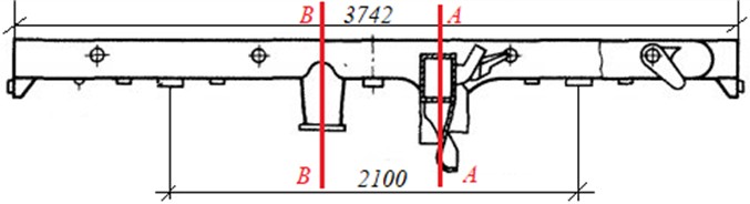
Fig. 2The sidewall sections of the bogie frame
4. Conclusions
Based on the results of the theoretical-numerical calculation, the following general conclusions can be made regarding the assessment of the vibration impact on the cross-sections of the subway car bogie frame:
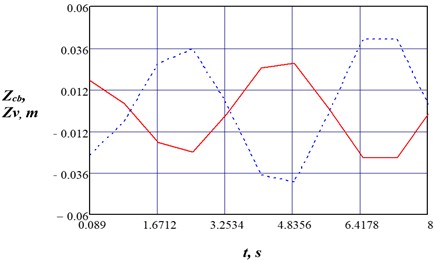
1) Fig. 3 shows a graph of vertical oscillations of the sidewall sections (A-A) of a subway car bogie and body oscillations during its movement along a track with a change in time . It follows from Fig. 3 that the process of oscillations of the bogie frame sections and the subway car body is harmonic. At a design speed of movement 100 km/h, the resulting oscillations (vertical displacements) are insignificant and amount to ± 4.8356 mm. At the same time, with increasing speed, they will increase. At a maximum speed 250 km/h, the maximum vertical oscillations of the bogie Zcb will reach ± 10.6931 mm.
Fig. 3Graph of vertical oscillations of the sidewall sections (A-A) of a subway car bogie as it moves along a track with changes in time
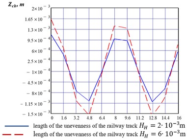
2) Fig. 4 shows a graph of the dynamic displacements of a metro car bogie from impact forces as it moves over time along a track with varying track roughness at a speed of 100 km/h. Clearly, as the roughness increases from 2 to 6 mm, the dynamic displacements of the subway car bogie frame from increase from ±1.131 mm to ±1.632 mm.
Fig. 4Graph of dynamic displacements of a subway car bogie due to impact forces as it moves over time along a track with varying unevenness at a speed of V= 100 km/h
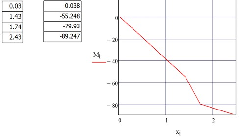
3) Fig. 5 shows the diagram of bending moments in the section of the sidewall of the subway car bogie frame (kN·m), while the compressive stress is equal to –48.425 MPa, in section A-A.
4) The data of the theoretical calculation carried out by the authors of this article are confirmed by the results of experimental studies carried out by the authors of the works [15-21].
5) As a result, a scientific substantiation of methods for increasing the reliability and durability of electric train bogie frames was carried out using a new mathematical model developed for calculating the residual life of electric train bogie frames at high speeds for the conditions of the Republic of Uzbekistan.
Fig. 5Bending moment diagram in the section of the sidewall of the subway car bogie frame in section A-A
References
-
G. Khromova, S. Khromov, Z. Mukhamedova, and B. Safarov, “Two-axle bogie of a railway vehicle,” Patent of the Republic of Uzbekistan No. IAP 06498, 2021.
-
S. Timoshenko, Strength of Materials: Part II – Advanced Theory and Problems. St. Petersburg: Publishing house “Lan”, 2002.
-
M. Spiryagin, C. Cole, Y. Q. Sun, M. McClanachan, V. Spiryagin, and T. McSweeney, Ground Vehicle Engineering series. CRC Press, 2014, https://doi.org/10.1201/b17029
-
B. J. Wang, Q. Li, Z. S. Ren, and S. G. Sun, “Improving the fatigue reliability of metro vehicle bogie frame based on load spectrum,” International Journal of Fatigue, Vol. 132, p. 105389, Mar. 2020, https://doi.org/10.1016/j.ijfatigue.2019.105389
-
E. Oganyan and G. Volokhov, “Calculations and strength tests carry - of locomotive structures: tutory. Manual,” FSBEI Educational and Methodological Center for Education in Railway Transport, Moscow, 2013.
-
M. Sobaś, T. Antkowiak, R. Grzechowiak, and R. Miklasz, “Development trends in the construction of gear running systems of rail vehicles (part 1),” Rail Vehicles, No. 3, pp. 33–51, Aug. 2017, https://doi.org/10.53502/rail-138448
-
M. Sobaś, “Development trends in the construction of gear running systems of rail vehicles (parts 2),” (in Polish), Rail Vehicles, No. 4, pp. 15–30, Nov. 2017, https://doi.org/10.53502/rail-138433
-
B. J. Wang, S. Q. Xie, Q., and Z. S., “Fatigue damage prediction of metro bogie frame based on measured loads,” Journal of Fatigue, Vol. 154, p. 106532, Jan. 2022.
-
Q. An, H. Zhao, P. Li, and M. Fu, “Fatigue strength analysis of bogie frames under random loads,” Advances in Mechanical Engineering, Vol. 11, No. 9, Sep. 2019, https://doi.org/10.1177/1687814019878018
-
J. Li, Z. Ren, Y. Wu, and R. An, “Fatigue damage assessment of high-speed train bogie frame load spectra based on phase reconstruction,” Engineering Failure Analysis, Vol. 159, p. 108008, May 2024, https://doi.org/10.1016/j.engfailanal.2024.108008
-
P. Kessler, “Development of routines for the automated comparison between calculation and test bench results of bogie frames in laboratory tests according to EN 13749,” (in German), TU Wien, Jan. 2021, https://doi.org/10.34726/hss.2021.80505
-
S. Abdurasulov, N. Zayniddinov, O. Khamidov, A. Yusufov, and S. Jamilov, “Stress-strain state analysis of cross beam of main frame of industrial electric locomotives PE2M and PE2U,” in The 3rd International Symposium on Civil, Environmental, and Infrastructure Engineering (ISCEIE) 2024, Vol. 3317, No. 1, p. 060011, Jan. 2025, https://doi.org/10.1063/5.0266927
-
S. Jamilov, A. Yusufov, O. Khamidov, O. Kasimov, and M. Vokhidov, “Mathematical modelling of heat exchange process of locomotive traction electric motors,” in The 3rd International Symposium on Civil, Environmental, and Infrastructure Engineering (ISCEIE) 2024, Vol. 3317, No. 1, p. 060012, Jan. 2025, https://doi.org/10.1063/5.0266932
-
S. Kudratov, A. Yusufov, O. Khamidov, and S. Samatov, “Diesel locomotives – Fault analysis and problem solving,” in The 3rd International Symposium on Civil, Environmental, and Infrastructure Engineering (ISCEIE) 2024, Vol. 3317, p. 060013, Jan. 2025, https://doi.org/10.1063/5.0266930
-
S. G. Tatarintseva, T. P. Satsuk, D. V. Udalova, and O. R. Khamidov, “Risk management and financial stability of transport companies,” in 2nd International Conference and Exposition on Mechanical, Material, and Manufacturing Technology (ICE3MT 2022), Vol. 2943, p. 040056, Jan. 2023, https://doi.org/10.1063/5.0150187
-
O. S. Ablyalimov and D. O. Rajibaev, “Research of fuel and energy indicators of modernized diesel locomotives (Uzte16m) on the section of the UzbekRailway,” in E3S Web of Conferences, Vol. 477, p. 00084, Jan. 2024, https://doi.org/10.1051/e3sconf/202447700084
-
D. O. Rajibayev, A. M. Miryakubov, and A. A. Mavlanov, “Study of the traction converter control system of the uzelr series of electric locomotives,” in E3S Web of Conferences, Vol. 458, p. 03016, Dec. 2023, https://doi.org/10.1051/e3sconf/202345803016
-
O. S. Ablyalimov and D. O. Rajibaev, “The economic impact of the UzTE16M3 diesel locomotive on the Marokand-Kattakurgan railway section,” in E3S Web of Conferences, Vol. 449, p. 02007, Nov. 2023, https://doi.org/10.1051/e3sconf/202344902007
-
G. Khromova, D. Radjibaev, A. Zabiyeva, A. Kenesbek, and A. Mavlanov, “Calculation of the main parameters of the two-line helical traction transmission of an electric locomotive based on diagnostic parameters,” Applied Sciences, Vol. 15, No. 4, p. 1730, Feb. 2025, https://doi.org/10.3390/app15041730
-
G. Khromova, D. Radjibaev, and A. Zabiyeva, “Method of calculation for dynamic strength of complex configuration frame structures of locomotives for transport engineering,” in E3S Web of Conferences, Vol. 474, p. 01032, Jan. 2024, https://doi.org/10.1051/e3sconf/202447401032
-
W. J. Kapelański and L. Mielcarek, “The method of determining design assumptions for bogie platform,” Rail Vehicles/Pojazdy Szynowe, No. 1-2, pp. 39–45, Nov. 2024, https://doi.org/10.53502/rail-190356
About this article

The authors have not disclosed any funding.
The datasets generated during and/or analyzed during the current study are available from the corresponding author on reasonable request.
The authors declare that they have no conflict of interest.
