Abstract
To evaluate the dynamic performance and operational safety of the main shaft system of the booster pump in fire station, modal characteristics under different conditions were studied. Adaptive tetrahedral meshing was adopted for mesh generation, and mesh convergence verification was conducted to ensure analysis accuracy. Free modal analysis was carried out, and the results showed that the vibration modes exhibit the characteristic of transitioning from low-order overall coordinated vibration to high-order local vibration. Pre-stressed modal analysis was also performed, and the results indicated that the spiral impeller is a high stress concentration area, while the stress distribution of the main shaft body is gentle. Harmonic response analysis was conducted for the primary guide vanes and secondary guide vanes. Combined with the rated operating parameters, it can be seen that the resonance peak ranges of the two guide vanes both avoid the excitation frequency, with no significant resonance amplification phenomenon observed. The research shows that the dynamic characteristics of this main shaft system meet the actual working requirements, and can provide a reference for the structural optimization and reliable operation of booster pumps in fire stations.
Highlights
- Adaptive tetrahedral meshing was adopted for mesh generation, and mesh convergence verification was conducted to ensure analysis accuracy.
- Free modal analysis was carried out, and the results showed that the vibration modes exhibit the characteristic of transitioning from low-order overall coordinated vibration to high-order local vibration.
- Harmonic response analysis was conducted for the primary guide vanes and secondary guide vanes.
1. Introduction
As the core hub of the urban emergency water supply system, the stable operation of booster pumps in fire stations directly determines the continuity and reliability of water supply pressure during fire rescue [1]. The main shaft system, as a key component of the booster pump, undertakes the critical task of converting mechanical energy into fluid kinetic energy and pressure energy. However, under the severe operating conditions of high-speed rotation and high fluid pressure, it is prone to structural failure caused by vibration coupling and stress concentration [2, 3]. Therefore, accurately elucidating the dynamic characteristics and stress distribution patterns of the main shaft system is essential to ensuring the safe and reliable operation of booster pumps in fire stations. For dynamic characteristics and vibration response analysis, representative studies are as follows: Bauomy [4] derived the mathematical solution of the dynamic modeling equation based on MATLAB to verify the situation where the structure resonates. El-Sayed [5] solved the nonlinear differential equations by using the averaging technique under the conditions of primary resonance and internal resonance, and modeled the systems with NIPPF and ANIPPF controllers, thereby obtaining analytical solutions.
Currently, existing studies mostly focus on the modal analysis of main shafts in general-purpose equipment such as ordinary centrifugal pumps and chemical pumps, and often overlook the coupled effects of high pressure, high-speed rotation, and gravity load unique to booster pumps. As a result, it is difficult to accurately reflect the real vibration characteristics under the pre-stressed state [6]. To further ensure the safety and reliability of the main shaft system, the dynamic characteristics and stress distribution laws should be studied through free modal analysis, pre-stressed modal analysis, and harmonic response analysis.
The innovations are mainly reflected in two aspects: (1) A multi-load coupled pre-stressed modal model was established, which incorporates rotational inertial load, maximum design pressure, and gravity field into the boundary conditions simultaneously, making it more consistent with the actual load environment. (2) For the two vibration-sensitive components, the primary guide vanes and secondary guide vanes, a wideband harmonic response analysis was carried out to clarify the resonance risks of the system under key operating conditions, thereby providing direct theoretical support for the safe operation.
2. Establishment of finite element analysis model
2.1. The composition and working principle of the main shaft system
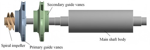
The main shaft system of the fire station booster pump is mainly composed of spiral impeller, primary guide vanes, secondary guide vanes, and main shaft body, as shown in Fig. 1. The spiral impeller is the core component of the booster pump. When the pump is running, it rotates at a high speed, does work on the fluid, converts mechanical energy into the kinetic energy and pressure energy of the fluid, realizes the pressurization of water, provides sufficient pressure for fire-fighting water supply, and ensures the smooth delivery of fire-fighting water. The primary guide vanes are used to guide and rectify the fluid passing through the spiral impeller. Because the flow state of the fluid is prone to disorder after gaining energy at the spiral impeller, the primary guide vanes can adjust its flow direction, allowing the fluid to enter subsequent components more smoothly and orderly, reducing energy loss and improving the efficiency of the pump. The secondary guide vanes further guide and optimize the fluid, which can make the velocity distribution of the fluid more uniform, convert more kinetic energy into pressure energy, and continuously organize the flow state at the same time to ensure that the fluid enters the main shaft body in a suitable state and enhance the effect of the entire pressurization process. The main shaft body is the supporting and connecting part of the entire main shaft. It provides an installation foundation and rotational support for other components, transmits power, enables the spiral impeller and other components to rotate stably, ensures the normal operation of the booster pump, and can also connect other parts of the pump, such as transmission devices, to ensure the effective transmission of power.
Fig. 1The composition of the main shaft system
2.2. Mesh generation and convergence verification
When conducting finite element analysis (FEA) on the main shaft system of the fire station booster pump, mesh generation and mesh independence verification are key steps to ensure the accuracy and reliability of the analysis results. Since the overall structure includes different components such as the spiral impeller, primary guide vanes, secondary guide vanes, and main shaft body, and each component has a certain complexity in shape, especially the spiral impeller and guide vanes have features such as curved surfaces, adaptive tetrahedral meshing type is used for mesh division, as shown in Fig. 2. This type of mesh can better adapt to complex geometric shapes.
Mesh independence verification is aimed at confirming that the generated mesh does not have a significant impact on the calculation results. Specifically, when the mesh density increases to a certain extent, the calculation results will no longer change noticeably with further mesh refinement. As shown in Tab.1, a series of meshes with different densities are generated. Starting from a relatively sparse mesh, the number of mesh elements is gradually increased to create finer meshes. For each type of mesh, the same modal analysis is performed to verify the deviation of the first-order natural frequency. If, as the mesh is continuously refined, the variation in results gradually decreases until the variation amount is less than the preset allowable error (generally 2 %), it indicates that the mesh at this point is sufficiently fine, and the calculation results no longer depend on further mesh division, thus meeting the requirements of mesh independence. Based on the verification results of the analysis accuracy according to the mesh size, the third grid accuracy was applied.
Fig. 2Meshing result

Table 1Meshing result
Mesh number | Element size (mm) | Number of elements | Number of nodes | First-order modal natural frequency (Hz) | Frequency change rate (compared with previous mesh) | Meeting mesh independence (set change rate < 2 % as satisfied) |
Mesh 1 | 8 | 203889 | 181145 | 118.50 | – | No |
Mesh 2 | 6 | 478621 | 429987 | 123.27 | 4.03 % | No |
Mesh 3 | 4 | 794405 | 749011 | 124.89 | 1.31 % | Yes |
Mesh 4 | 2 | 1039574 | 998756 | 125.12 | 0.18 % | Yes |
3. Analysis of model characteristics
3.1. Theoretical model of modal analysis
For a linear time-invariant system with degrees of freedom, in common dynamic problems, under the condition of free mode, its dynamic equilibrium equation is as follows:
where is the mass matrix, is the system stiffness matrix and is the displacement response of each point in the system.
Under the condition of undamped free vibration, Eq. (1) can also be expressed as:
where is the mode shape vector, and ω is the natural angular frequency.
Under pre-stressed conditions, the dynamic equilibrium equation can be expressed as:
where is the geometric stiffness matrix generated by the load.
3.2. Free modal analysis
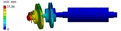
Under free modal conditions, the first six modes of the main shaft system are approximately rigid displacements. Thus, the seventh mode is considered as the first effectively practical mode for analysis. Through finite element calculations, the first six mode shapes can be obtained, as presented in Fig. 3.
Fig. 3The first six mode shapes in free modal condition
a) The first mode shape

b) The second mode shape

c) The third mode shape

d) The fourth mode shape

e) The fifth mode shape
f) The sixth mode shape
The first mode shape exhibits a low-order coordinated vibration. The displacement distribution of the left impeller and adjacent components is relatively gentle, with the displacement peak concentrated near the left impeller, and the displacements of the shaft and right components are small. The second mode shape has more obvious local characteristics. The displacement peak is concentrated in a specific area of the left impeller, showing local coupled vibration between the left impeller and adjacent components. The third mode shape is a segmented local vibration. The displacement peak is concentrated in the blade or edge area of the left impeller, and the displacements of the middle and right components are relatively weak. The fourth mode shape is dominated by the local deformation of the middle disk. The displacement peak reaches 41.08 mm, and the red area is concentrated on the middle disk, while the displacements of the left and right components are relatively secondary. The fifth mode shape shows relative misalignment or torsional vibration of multiple components on the left. Obvious relative deformation occurs in the two disk-like components on the left, and the red area is distributed at the edges of the two disks. The sixth mode shape has the highest frequency among the first six orders. The displacement peak reaches 44.29 mm, and the mode shape is dominated by the local deformation of the right disk. The red area is concentrated on the right disk, and the displacement of the left component is relatively weak.
3.3. Pre-stressed modal analysis
Under the maximum load condition, the boundary conditions for pre-stressed modal analysis are set as shown in Fig. 4. To simulate the supporting effect of bearings, cylindrical constraints are applied to both sides of the main shaft. The angular velocity of the main shaft is set to 6000 r/min to simulate the inertial load generated by rotation. The maximum design pressure of 1.5 MPa is applied to the pressure-acting area to simulate the fluid pressure. The gravity field is introduced to make the structure subject to gravity. The pre-stressed modal analysis first calculates the static stress and deformation of the structure based on these boundary conditions, and then carries out modal analysis under this pre-stressed state, so as to obtain the natural vibration characteristics considering the influence of actual static loads.
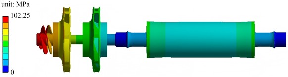
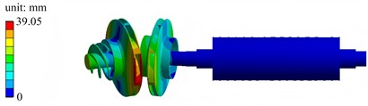
Stress analysis results are shown in Fig. 5. The spiral impeller, as a core rotating component directly bearing rotational inertia and fluid pressure, has high and concentrated stress, close to the maximum stress value of 102.25 MPa. The primary guide vanes receive the fluid flowing out of the spiral impeller. Under the action of fluid dynamics, the stress is in the medium-high range, showing the characteristic of transitioning from the high stress on the impeller side to subsequent components, and undertaking the functions of fluid dynamic transmission and partial load bearing. The secondary guide vanes further guide and rectify the fluid. The fluid force is more stable, the degree of stress concentration is reduced, and the stress distribution is relatively uniform at a medium level, playing the roles of load transition and fluid regulation. The main shaft body mainly transmits rotational motion, and the forces it bears are mainly stable torque and axial force. There is no obvious concentrated load or direct impact of complex fluid, so the stress level is extremely low, the distribution is gentle, and the force-bearing state is safe and stable.
Fig. 4The boundary conditions for pre-stressed modal analysis
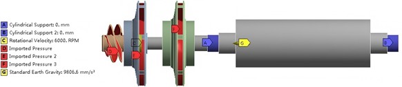
Fig. 5Stress analysis results
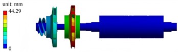
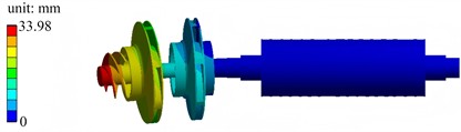
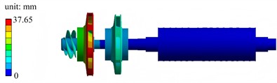
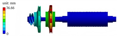
The first six mode shapes under the pre-stressed modal condition are shown in Fig. 6. The first-order mode shape exhibits low-order globally coordinated vibration, and the displacement distribution of the left-side components is gentle. The second-order mode shape has a frequency close to that of the first-order, with more prominent local vibration characteristics concentrated in the left-side region. The third-order mode shape shows an increased frequency, and the vibration tends to be localized, with significant local deformation in the regions of the left impeller and guide vanes. The fourth-order mode shape has a higher frequency and a more complex mode shape, with coupled local relative deformation occurring in multiple left-side components. The fifth-order mode shape has a further increased frequency, and there is obvious relative motion between the left-side components, with a more extensive deformation distribution. The sixth-order mode shape features vibration concentrated in specific local regions of the middle and left sides, presenting a high-frequency local vibration mode. As the order (frequency) increases, the vibration gradually changes from low-order globally coordinated motion of the entire system to high-order localized deformation. These mode shapes reflect the dynamic behavior of the assembly under the pre-stressed condition, which is closer to the actual operation, and are of great significance for evaluating the resonance risk and dynamic stability.
Table 2Comparison results of natural frequencies under different boundary conditions
Modal order | 1 | 2 | 3 | 4 | 5 | 6 |
Natural frequencies in free modal analysis / Hz | 124.89 | 139.92 | 205.56 | 277.38 | 278.79 | 315.07 |
Natural frequencies in pre-stressed modal analysis / Hz | 158.02 | 159.74 | 237.88 | 291.19 | 323.65 | 384.42 |
Comparison results of natural frequencies under different boundary conditions are shown in Table 2. It can be seen that prestress enhances the stiffness of the structure, improving its ability to resist vibration deformation and increasing the natural frequency accordingly. The higher-order modes are more significantly affected by prestress because higher-order vibrations involve more local deformations, and the effect of prestress on local stiffness is more prominent.
Fig. 6The first six mode shapes in pre-stressed modal condition
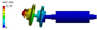
a) The first mode shape
b) The second mode shape
c) The third mode shape

d) The fourth mode shape
e) The fifth mode shape
f) The sixth mode shape
3.4. Harmonic response analysis
Through modal analysis, it is known that the maximum displacement of resonance mainly occurs on the primary guide vanes and secondary guide vanes. To further study the response of these two parts to different frequencies, harmonic response analysis can be conducted on them. Set the sweep frequency range to 2-400 Hz, the external load to 10 N, and the phase of the unbalanced load to 0°, and the response curves of relative vibration peaks can be obtained as shown in Fig. 7. According to the rated operating parameters of the main shaft system, the operating speed is 6000 r/min, and the corresponding excitation frequency is 100 Hz. As can be seen from the harmonic response curves, the response of the primary guide vanes is in a relatively stable rising phase near 100 Hz, with no obvious resonance peak. The dominant resonance peak of the secondary guide vanes is concentrated in the lower medium- and low- frequency range. 100 Hz has avoided its strong resonance interval, and at this time, the amplitude is in a decreasing and fluctuating state after the dominant peak, without significant resonance amplification matching 100 Hz. Therefore, it meets the operating requirements.
Fig. 7The response curves of relative vibration peaks
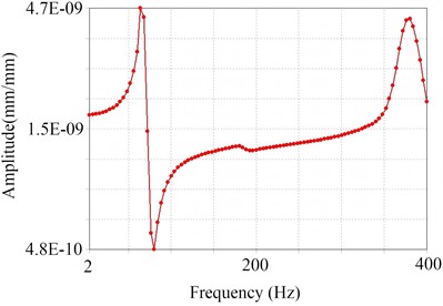
a) Primary guide vanes
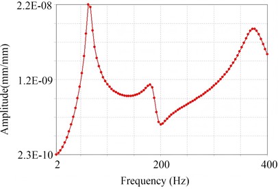
b) Secondary guide vanes
4. Conclusions
1) The main shaft system is meshed using a triangular and tetrahedral hybrid meshing method. The mesh density is adjusted for different components, and through mesh convergence verification, the 4 mm element size is determined as the optimal solution. With a frequency variation rate of 1.31 % (less than 2 %), the model accuracy meets the analysis requirements and can accurately reflect the structural geometric characteristics and mechanical behavior.
2) The dynamic performance and stress state of the main shaft system of the booster pump in the fire-fighting pump station meet the design expectations, which can ensure stable operation. Meanwhile, the FEA method and results in this paper can provide a reference for the structural design, modal optimization, and resonance risk assessment of similar rotating machinery.
References
-
X. Xu, Y. Wang, and A. Zhao, “Optimization design of low-shaft-power single-stage centrifugal fire pump based on orthogonal experiment,” Processes, Vol. 13, No. 4, p. 1186, Apr. 2025, https://doi.org/10.3390/pr13041186
-
L. Shi and L. Liu, “Vibration test measures for pump fault diagnosis,” Journal of Electronic Research and Application, Vol. 5, No. 6, pp. 6–10, Nov. 2021, https://doi.org/10.26689/jera.v5i6.2683
-
M. Awsan, “Data driven-based model for predicting pump failures in the oil and gas industry,” Engineering Failure Analysis, Vol. 145, No. 1, p. 107019, Mar. 2023, https://doi.org/10.1016/j.engfailanal.2022.107019
-
H. Bauomy and A. Taha, “Nonlinear saturation controller simulation for reducing the high vibrations of a dynamical system,” Mathematical Biosciences and Engineering, Vol. 19, No. 4, pp. 3487–3508, Jan. 2022, https://doi.org/10.3934/mbe.2022161
-
A. T. El-Sayed and H. S. Bauomy, “NIPPF versus ANIPPF controller outcomes on semi-direct drive cutting transmission system in a shearer,” Chaos, Solitons and Fractals, Vol. 156, No. 1, p. 111778, Mar. 2022, https://doi.org/10.1016/j.chaos.2021.111778
-
H. Bauomy and A. T. El-Saye, “Oscillation controlling in nonlinear motorcycle scheme with bifurcation study,” Mathematics, Vol. 13, No. 1, p. 3120, Jan. 2025, https://doi.org/10.3390/ math13193120
About this article

The authors have not disclosed any funding.
The datasets generated during and/or analyzed during the current study are available from the corresponding author on reasonable request.
The authors declare that they have no conflict of interest.
