Abstract
In the current era of independent development and market relations, the importance of railways continues to grow steadily. This, in turn, places great responsibility on the system of measures aimed at ensuring railway reliability. However, despite the advantages and advancements of the railway industry, it still faces technical complexities that can lead to track deterioration. In heavily loaded and high-speed railway sections, the interaction between the rolling stock and the track causes various issues in the rail joint zones – such as the development of defects and irregularities, deterioration of track geometry, reduction of track stability, as well as problems related to noise and vibration that must be mitigated. To address these challenges, scientific studies and experimental investigations have been conducted on the installation of elastic under-sleeper pads in the rail joint zones. These studies aim to modify the vertical stiffness transferred from the wheelsets of the rolling stock to the track structure, reduce harmful vibrations and oscillations, and thereby ensure uniform stability along the entire track. The conducted research, testing, and their results are presented in this article.
Highlights
- The photograph, taken during research conducted by a third author in 2024-2025, depicts the process of studying issues in the railway superstructure elements within the rail joint zones.
- The photograph, taken by the third author during research conducted in 2024-2025, depicts the processes of measuring and monitoring the railway bridge transition and rail joint zones using the SUP-3 track gauge template.
- The process of installing elastic sleeper pads in the rail joint zone.
1. Introduction
At present, the primary objective of railway transport systems worldwide, including in our country, is to ensure the timely, high-quality, and economically efficient satisfaction of all transportation needs of the population and economic entities. In addition, increasing the efficiency and reliability of the railway transport system and ensuring the stability and durability of the track structure remain key priorities [1], [3], [4].
In our country as well, a number of state-level projects are being developed to organize the operation of heavy freight trains and high-speed passenger trains. In the coming years, large-scale construction and implementation works are planned within these projects, through which important national objectives such as “bringing distant places closer and making heavy loads lighter for our citizens” will gradually be realized. Ensuring the coordinated and efficient interaction between heavily loaded and high-speed trains and the railway track infrastructure along designated routes represents a traditional yet increasingly critical technological challenge. Maintaining the reliability, stability, and safety of both the rolling stock and the elements of the railway infrastructure within this process has become one of the most pressing issues of today and the near future [2], [5], [11]. The amplification of such harmful vibrodynamic effects leads to a reduction in track performance, particularly in the rail joint zones, where defects and irregularities tend to develop more rapidly. Consequently, on heavily loaded and high-speed railway lines, the frequent occurrence and progression of defects especially in rail joint zones necessitate timely detection, analysis, and effective maintenance interventions to ensure the continued reliability and stability of the railway infrastructure [6-8].
2. Research methodology
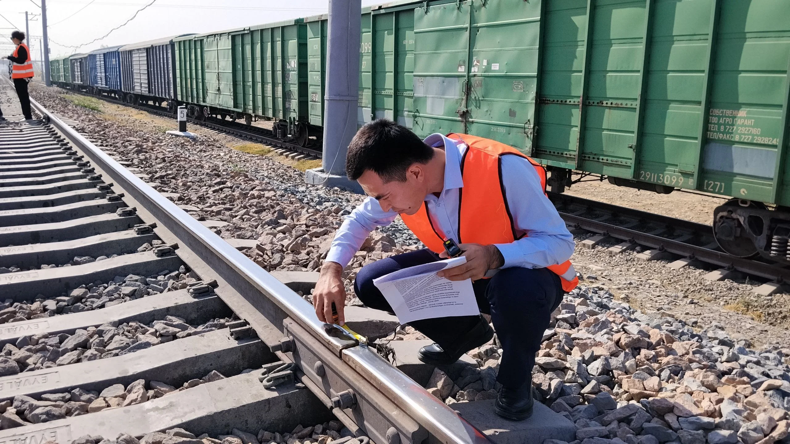
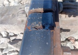
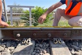
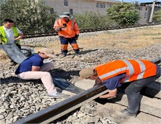
Scientific studies and experimental investigations have shown that the above-mentioned issues are most prominently manifested in the rail joint zones compared to other parts of the track. Moreover, these defects are relatively easier to detect, which makes this area particularly significant for diagnostic and maintenance purposes. As illustrated in Fig. 1, and explained in the following discussion, typical manifestations of such problems include: settlement of one or both rails, track misalignment, the occurrence and progression of rail defects along the rail geometry, crushing, cracking, and splitting of joint bars (four- or six-bolt fishplates), breakage or tearing of under-sleeper pads, deformation or failure of intermediate fastening elements, loosening and fatigue-related damage, rail corrugation, distortion or misalignment of sleeper spacing, cracking or breaking of sleepers, deformation of the ballast prism geometry, excessive crushing and contamination of ballast aggregates, as well as settlement, irregularities, and residual deformations in the subgrade layer. The increasing prevalence of these defects and deformations in the rail joint zones highlights the scientific and practical importance of ongoing research in this field, emphasizing the need for effective engineering solutions to enhance the durability and stability of railway tracks [8], [9], [12].
Fig. 1Defects in the rail joint zones. The photograph, taken during research conducted by a third author in 2024-2025, depicts the process of studying issues in the railway superstructure elements within the rail joint zones

The railway maintenance enterprises within the railway sector carry out scheduled technical servicing of the tracks to address the aforementioned issues. This recurring need for intervention increases the overall maintenance and repair costs, as well as the demand for materials and labor, in ensuring track alignment, operational reliability, and traffic safety within the rail joint zones. It has been observed that the current maintenance of rail joint zones accounts for approximately 30-40 % of the total railway track maintenance expenses [12].
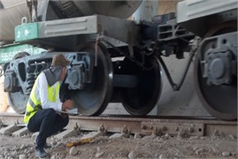
As the use of reinforced concrete sleepers in the superstructure of railway tracks has expanded, the dynamic stiffness of the rail joint zones has also increased, making it more challenging to ensure their priority and reliability. Over time, numerous measures, scientific studies, and engineering developments have been implemented to reduce the additional forces and harmful effects exerted by wheelsets on rail joints. Based on measurement control work, continuous analyses, and scientific investigations conducted to assess the condition of rail joint zones, experimental studies have been carried out to reduce the harmful vibrodynamic effects generated by the passage of rolling stock, decrease the level of vibrations in track components, extend the service life of superstructure materials, and ensure the reliability of rail joint zones. To achieve these objectives, elastic under-sleeper pads were applied to the sleepers (six sleepers) within the rail joint zones. The experimental test sites were selected based on their need for corrective maintenance and their problematic conditions. These included rail joint zones at the transition from continuous welded rails to standard rails, sections with artificial structures, and areas at bridge approaches. The exact locations of these rail joint zones can be observed in Fig. 2.
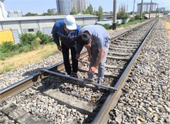
Fig. 2Inspection of bridge transition and rail joint zones as the main object of the study. The photograph, taken by the third author during research conducted in 2024-2025, depicts the processes of measuring and monitoring the railway bridge transition and rail joint zones using the SUP-3 track gauge template
In order to conduct scientific and experimental studies on the installation of elastic under-sleeper pads to ensure the stability and reliability of the rail joint zones selected as the research object, all organizational measures were carried out to successfully operate the railway at kilometer 3384, 8th picket of the section between Salor-Chuqursoy stations, under the jurisdiction of the Salor Railway Distance Enterprise. This operation was conducted in accordance with the scheduled movement of freight and passenger trains, while fully ensuring traffic safety.
The following materials, equipment, and tools required for conducting the experimental study and for railway maintenance were used: Elastic under-sleeper pads (three pairs, six rubber pieces), Special adhesive for attaching the pads to the sleepers, Brushes for spreading the adhesive, Hydraulic jack for lifting the track, Crowbar, Track measurement template, Measuring tape, Scraper for cleaning sleeper beds from ballast, Electric sleeper tamper, and other necessary tools.
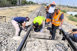
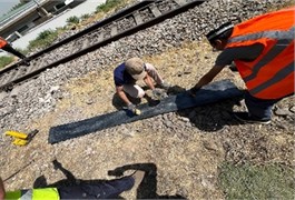
During the experimental test, all work was carried out in strict compliance with railway operation rules, train movement safety requirements, railway work execution guidelines, labor protection, and safety regulations. The first step in the process was the placement of elastic rail pads under the sleepers, which required cleaning the sleeper seats from crushed stone to ensure that the pads could be installed without obstruction. This task was performed with the assistance of the track maintenance crew from Salor railway section. During the test, no train movement restrictions “window time” closures or speed limit measures were applied. Under these conditions, the installation of the elastic rail pads proved to be highly effective, as it did not interfere with the scheduled train operations or cause economic losses (delayed cargo deliveries, fines, etc. e.g.). After creating the working conditions for gluing the elastic rail pads under the sleepers in the rail joint zone, the sleeper seats were thoroughly cleaned using scrapers. The underside surfaces of the BF-70 sleepers were prepared to match the dimensions of the elastic rail pads, which were pre-cut on a special machine. Adhesive application was carefully performed for each sleeper individually, and the sleeper seats were subsequently filled with crushed stone to restore proper support. These experimental test procedures are illustrated in detail in Fig. 3. Once the elastic pads were fully installed under all six sleepers in the rail joint zone, all subsequent work for track leveling, adjustment, and ensuring safe train operations was completed.
The use of elastic under-sleeper pads in the rail joint zones increases the reliability of these areas, reduces the harmful effects of vibration by 1.5-2 times, shortens the vibration periodicity by 15 %, and positively influences the stiffness characteristics of the sleeper. It also ensures faster attenuation of harmful vibrations in the rail joint zones, thereby extending the service life of the track superstructure materials and contributing significantly to maintaining the overall stability and performance of the railway track [12].
Reducing the stiffness of the rail foundation in the rail joint zones of reinforced concrete sleeper tracks and ensuring its stability has become one of the pressing issues today. This can be achieved by adjusting the stiffness of the track superstructure materials in the rail joint zone, improving the stiffness and elasticity characteristics of the intermediate fastening pads, and by using the elastic sleeper pads that we are testing in our scientific research and experimental trials. Therefore, it is necessary to clarify their elasticity characteristics. As is known, the stiffness of the rail joint zone of the railway and its modulus of elasticity are interrelated:
where: – modulus of elasticity of the railway, measured in [MPa]; – stiffness of the railway, measured in [MN/m]; – distance between reinforced concrete sleeper axes, measured in meters.
Fig. 3The process of installing elastic sleeper pads in the rail joint zone. The photograph, taken by the third author on August 29, 2025, shows the process of conducting experimental research on the installation of elastic under-sleeper pads
The overall stiffness of the transition zone, where the continuously welded track changes to standard rail sections – particularly in areas with artificial structures and bridge approaches – can be expressed in functional form by the following equation:
The overall stiffness of the rail joint zone is formed by the sum of the stiffnesses of the individual elements connected in parallel within the joint zone. Therefore, the total stiffness depends on the stiffness of each component and can be determined using the following expression:
Ensuring the stability of the railway track in the rail joint zone by adjusting the stiffness of the rail joint zone and its elements to a certain degree has become a pressing issue. The main problems in rail joints arise because the train wheels do not move over a single continuous element (rail), the rails are positioned relative to each other at different vertical and horizontal levels ( or ), the sleeper foundation settles unevenly at different points, the subgrade has varying strength, and the track materials have different stiffness. This causes stiffness transitions in the rail joints or transition sections – from low-stiffness areas to high-stiffness areas, or vice versa.
In simpler terms: High-stiffness sections correspond to bridges, tunnels, areas with artificial structures, and track sections without ballast; Low-stiffness sections correspond to rail joints on ballasted tracks, bridge approach sections, embankments in front of abutments, and other ballasted track sections.
The variation in stiffness in the rail joints of the section transitioning from a ballastless track to standard rails and the bridge approach sections is determined by the ratio of stiffness change to the length, which can be expressed through the derivative of track stiffness along the -axis () and is represented by the following expression:
After determining the equivalent elasticity modulus of the railway rail joint zone and the elastic deflection of the rail, the stressed state of the track is calculated for each cross-section of the rail (as per standard regulations), primarily focusing on the rail joint zones. To determine the residual deformation of the ballast, analyses of various studies were conducted. As a result, the data obtained by the researcher A.I. Gasanov were selected, showing the relationship at the transition section of the rail between the settlement of the crushed stone under the sleeper and the force acting on the reinforced concrete sleeper in the rail support zone:
where: – residual deformation of the track, mm; – approximation coefficient, equal to 2.45; – pressure acting on the sleeper, kg/sm²; – pressure on the sleeper under which no settlement occurs in the underlying ballast, equal to 2800 kg/sm2. This value was obtained by S. N. Popov based on experimental studies and scientific research conducted on the sleeper ballast layer. It can be applied to crushed stone with normal grain size under dry conditions. S. N. Popov determined the development intensity of ballast residual deformations after 10000 load pulsations. Therefore, according to the above formula for , the residual deformation of the ballast is assumed to develop after 10000 dynamic load pulsations from the moving wheelsets. Vibration generated during train movement can reduce the resistance of the railway along its length to harmful effects (such as oscillations and stresses), according to foreign literature, by up to 50 % – which can lead to situations where the track shifts or lifts.
3. Research results
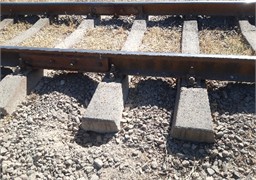
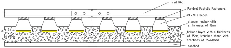
According to the methodology provided for the study, the railway joint zone designated as the test object was thoroughly examined and the results analyzed, revealing the following: the left and right tracks exhibit settlement, which is visually noticeable along the railway at a distance of 1.5-2 meters from the joint; there is residual deformation; the ballast under the sleepers has a particle size within the standard 25-60 mm but is partially crushed and contaminated. For conducting the experimental tests, the upper track structure materials in the selected railway joint area are in the following condition during operation: the section under study carries an annual load of 450 million t·km (gross); the rail type in the joint section is R65, with partial defects present; sleepers are reinforced concrete BF-70; fastening elements are Pandrol Fastclip (P-350); the ballast layer is first category (according to GOST 7392-2014) as shown in Fig. 4 [5]. Conducted experimental studies on the experimental section, at the passage of trains from the joint zones with the use of elastic sleeper pads with different thicknesses are proposed below as follows (Fig. 4).
Fig. 4Rail joint zone No. 1 using 18 mm thick resilient under-sleeper pads
Equipment for measuring joint zone vibrations: To assess the transmission of dynamic effects from rolling stock to the rail and lower components of the joint zone, both without and with elastic under-sleeper pads, the Mobile Engineering Seismic-Metric Station (MISS), developed in 2016 at the Institute of Mechanics and Seismic Resistance of Structures, is used. Detailed information regarding the station’s structure, operating principles, preparation for measurements, calibration methodology of measurement channels, and the procedure for recording vibrations of the object during dynamic processes is provided in the scientific and technical report [6].
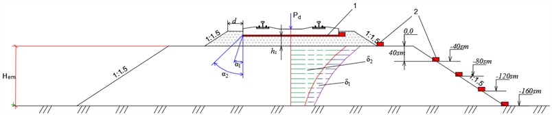
To determine the propagation of vibrations, vibro-displacements, logarithmic decrement, vibration velocities, and vibration accelerations in the ballast layer and underlying soil of the rail joint zone resulting from rolling stock passage, the following SM-3 oscillograph sensors are used: Number of sensors for measuring vibro-displacements and vibration velocities in a three-coordinate system – 3 units. Before starting the test research – experiment, all instruments and equipment are checked to ensure they are in working condition. The SM-3 oscillograph, computer, and necessary devices are connected to the power supply in compliance with safety regulations. Once the freight train moves through the section of the railway with the joint zone under study, the experiment is conducted while fully observing train traffic safety. The train passes through the joint zone without any interference with its movement or speed. As the second freight train begins to move through the section, it is observed that the vibrodynamic effects, noise, vibrations, and oscillations in the track structure materials, which were recorded during the passage of the first freight train, are significantly reduced due to the installation of elastic under-sleeper pads. These effects generate varying vibrations at each sensor in the three-coordinate system , and the data is continuously recorded on the computer-laptop. The measurement methodology is carried out according to the scheme shown in Fig. 5.
Fig. 5Stress distribution (epure) and vibration sensor placement scheme with the installation of an elastic under-sleeper pad: 1 – under-sleeper pad (elastic pad), 2 – SM-3 sensor, hs – thickness of ballast layer under the sleeper (40 mm), d – width of the ballast prism (45 mm), α1 — angle of stress distribution in the ballast prism when the under-sleeper pad is not installed, α2 – angle of stress distribution in the ballast prism when the under-sleeper pad is installed, δ1 – stress profile (epure) in the ballast caused by the load from above when the under-sleeper pad is not installed (MPa), δ2 – stress profile (epure) in the ballast caused by the load from above when the under-sleeper pad is installed (MPa), Pd – dynamic stress from the rails, kN
As the volume of freight transport and the loading of trains increases on the railways of our Republic, and as the frequency of high-speed passenger trains grows, the harmful vibrodynamic forces resulting from the interaction between the track and the rail joint zones also increase. This further underscores the relevance and importance of ongoing scientific and experimental research aimed at ensuring the safety and priority of train operations.
The under-sleeper elastic pads proposed for application under Uzbekistan’s railway conditions have distinctive advantages and implementation features compared to the transition zone studies conducted by foreign researchers such as H. Wang and V. Markine, as well as the elastic sleeper pads developed by Getzner. Unlike these, our proposed pads can be easily applied to all rail joint and transition zones, are simple to install, maintain, and replace, require minimal labor and cost, and offer several additional practical and economic benefits.
Test studies conducted to reduce the harmful vibrational effects that contribute to the development of the above-mentioned defects and malfunctions have demonstrated the positive outcomes of using elastic under-sleeper pads in the rail joint zones. Based on these results, the following conclusions and recommendations are made to improve the performance and extend the service life of track superstructure materials.
4. Conclusions
1) It is crucial to study the causes of problems in rail joint areas on high-traffic railway sections in Uzbekistan, analyze them, and scientifically investigate the impact of harmful vibrations on the elements of the track superstructure.
2) The use of elastic under-sleeper pads allows partial damping of dynamic forces (↓Pdn) and vibrations transmitted from the sleeper to the ballast, which leads to a 15 % reduction in the vibration period
3) Compared to other sections of the track, the joint zones of rails experience more frequent defects. It is necessary to address these problems, reduce the occurrence of defects, and shorten the maintenance and repair time allocated for track upkeep by implementing new corrective measures.
4) The use of elastic under-sleeper pads in the rail joint zones increases the reliability of these areas, reduces the harmful effects of vibration, decreases vibration velocity and acceleration by 10 % and 5 % respectively, and has been scientifically proven to have a positive effect on the stiffness characteristics of the sleeper.
5) Elastic under-sleeper pads ensure the rapid damping of harmful vibrations in the rail joint zone, thereby increasing the service life of the track structure materials and significantly contributing to the maintenance of railway priority. Their widespread use in the railway industry is considered effective.
References
-
A. Abdujabarov, M. Mekhmonov, P. Begmatov, F. Eshonov, and M. Khamidov, “Consideration of the environmental impact on the seismic inertial forces of the railway track in difficult conditions,” in Problems in the Textile and Light Industry in the Context of Integration of Science and Industry and Ways to Solve Them: PTLICISIWS-2, Vol. 3045, p. 030097, Jan. 2024, https://doi.org/10.1063/5.0197332
-
M. Khamidov and S. Makhamadjonov, “Ensuring and maintenance of the road stagnation in the butt zones on the lines of JSC “Uzbekistan temir yo‘llari”,” Scientific and Technical Magazine on Problems of Architecture and Construction, pp. 134–138, 2024.
-
A. Abdujabarov, F. Eshonov, P. Begmatov, M. Mekhmonov, and M. Khamidov, “Calculation of the seismic stress state of the ground-gallery system,” in Problems in the Textile and Light Industry in the Context of Integration of Science and Industry and Ways to Solve Them: PTLICISIWS-2, Vol. 3045, p. 030098, Jan. 2024, https://doi.org/10.1063/5.0197333
-
K. S. Lesov, Z. Z. Ergashev, M. K. Kenjaliyev, and S. A. Tadjibaev, “Quantitative characteristics of construction and reconstruction of railway sections in Uzbekistan,” in E3S Web of Conferences, Vol. 401, p. 03024, Jul. 2023, https://doi.org/10.1051/e3sconf/202340103024
-
A. K. Abdujabarov, M. K. Xamidov, and M. K. Mekhmonov, “Study and mitigation measures for the effects of stresses and vibrodynamic forces on rails resulting from the movement of freight train wheels,” Journal Engineer, pp. 174–176, 2025.
-
M. Mekhmonov, S. Makhamadjonov, and A. Uralov, “Stabilization of embankments and coastal bridges with reinforced concrete piles,” in E3S Web of Conferences, Vol. 508, No. 9, p. 08018, Apr. 2024, https://doi.org/10.1051/e3sconf/202450808018
-
K. S. Lesov, S. A. Tadjibayev, G. R. Khalfin, and M. M. Mirkhanova, “Reinforcement of the embankment slopes with volumetric geogrids of the roadbed and the study of their stability,” in The 3rd International Symposium on Civil, Environmental, and Infrastructure Engineering (ISCEIE) 2024, Vol. 3317, p. 030041, Jan. 2025, https://doi.org/10.1063/5.0267388
-
E. S. Ashpiz, Railway Way: Textbook. Moscow: FBGU DPO Educational and methodological Center for education in railway transport, 2021.
-
A. Abdujabarov, P. Begmatov, F. Eshonov, M. Mekhmonov, and M. Khamidov, “Influence of the train load on the stability of the subgrade at the speed of movement,” in E3S Web of Conferences, Vol. 264, p. 02019, Jun. 2021, https://doi.org/10.1051/e3sconf/202126402019
-
H. Wang and V. Markine, “Corrective countermeasure for track transition zones in railways: Adjustable fastener,” Engineering Structures, Vol. 169, pp. 1–14, Aug. 2018, https://doi.org/10.1016/j.engstruct.2018.05.004
-
A. H. Abdujabarov, M. K. Khamidov, and H. Мekhmonov, “Testing of railway construction using elastic sleeper gaskets in the butt zone,” Scientific and Technical Magazine Problems of Architecture and Construction, pp. 249–253, 2024.
-
“Materials of the Getzner company,” Railway Engineering Review, Vol. 7, pp. 47–53, 2016.
About this article

The authors have not disclosed any funding.
The datasets generated during and/or analyzed during the current study are available from the corresponding author on reasonable request.
The authors declare that they have no conflict of interest.
