Abstract
The article presents the design of the transition section to be used in different conditions in the region of junction of roadbed and the bridge, establishment and reasons of vertical shifts under the action of vibro-dynamic forces which appear when trains are driven along transition section. Likewise, in the sections of the foundation of the roadbed and the bridge, the types and types of a variety of defects caused by this fact, such as when the pressure of the weight of constant and temporary forces dropped on the rolling stock passes the active pressure of the ground (), which acts on the support of the bridge shore at the point of the passage, are provided. In order to minimize the active effort at the junction formed by soil, reinforce and make the junction location defect-free, reinforced concrete piles are driven into the embankment to act as bases of junction location between the roadbed of the railway and the bridge location and a formula of computing the spacing of the piles has been contributed taking into consideration outer influences.
Highlights
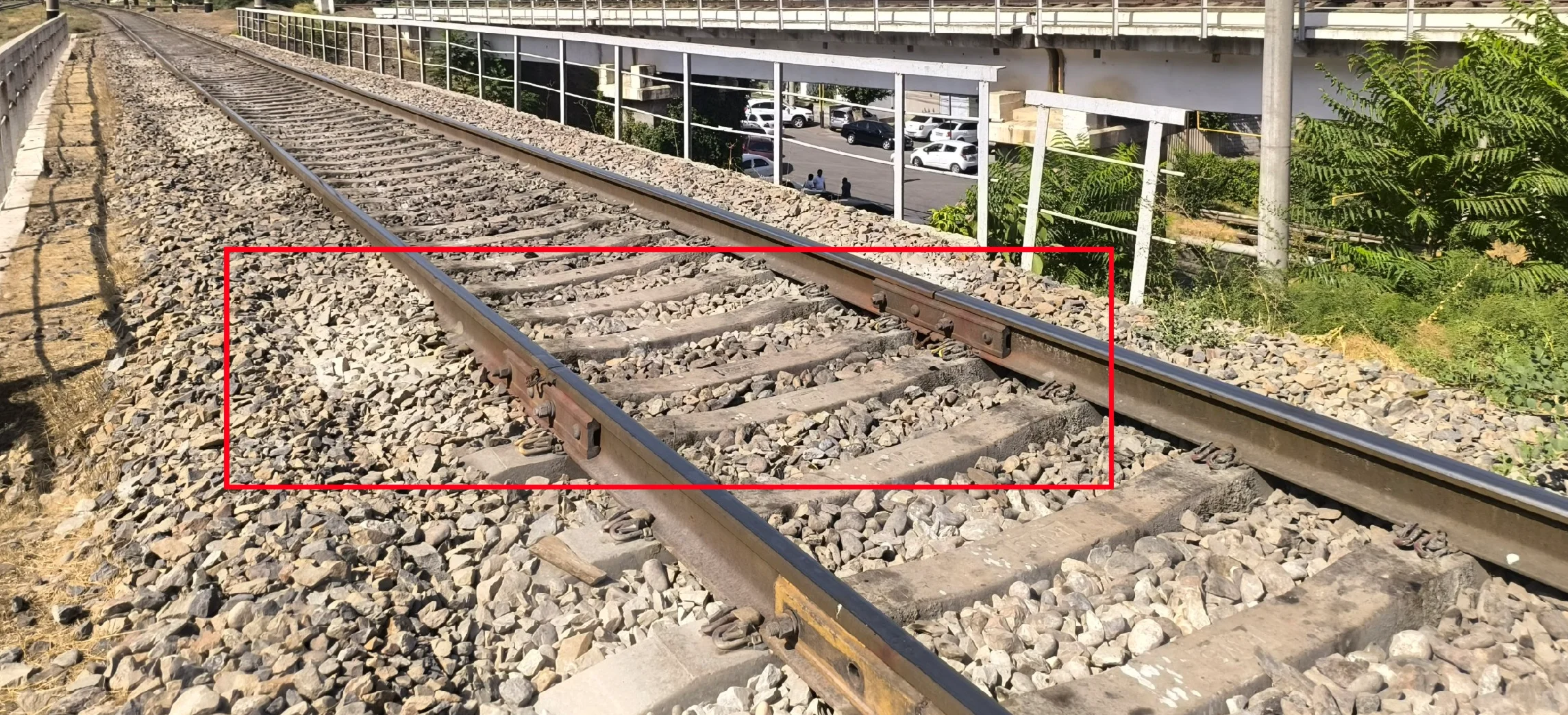
- The photograph, taken by the second author on August 25, 2025, illustrates issues with the road superstructure in the transition zone from the earthwork to the bridge (published with the author's permission)
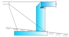
- Raised portion of the soil foundation at the approach section in front of the bridge abutment reinforced with piles: 1 - bridge abutment; 2 - reinforced concrete piles; L - length of the piles
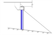
- Computation of the extra intersection area of submerged base of the coastal support with the soil: 1 - retaining wall; 2 - counter fortunes; 3 - submerged support surface of the retaining wall; 4 - road subgrade; 5 - excavation areas; 6 - mass of soil in landslides; Ea - active earth pressure
1. Introduction
Bridge supports can be divided into abutments and intermediate support. The supports are necessary in transferring the weight of the superstructure, live loads and wind among other horizontal and vertical forces to the foundation soils. According to their construction, supports can be classified as follows: heavy supports This group includes stone, mass concrete, or reinforced concrete (monolithic, precast monolithic, or fully precast). In large rivers with intensive ice flow and other unfavourable conditions, as well as heavy supports, pile foundations (built in the shape of a row or a few rows of piles bonded with a cap beam (rigel) upon which the superstructure is mounted), have been used since the early stages of bridge construction and to the present day.
One of the most significant components of bridge structures that are very crucial is abutments which help to secure the contact between the superstructure and the approach embankment. The bonding of the bridge to the railway embankments is made possible using the abutments. The primary criteria of such a connection are that there should be a smooth transition onto the bridge owing to the slow change in the rigidity of the railway base
This is mainly done by absorbing the horizontal pressure caused by weight of the supporting soil and temporary loads on embankment behind the abutment, but avoiding large vertical movements at the top of the abutment. Also, there is the compensation of the changes in the stiffness achieved by using special transition slabs behind the abutment. In order to allow the embankment not to drift towards the span, it is stabilized with the help of a cone, which, in turn, should be strong and stable enough.
During the 1960s and 1970s numerous kinds of supports were developed which came to be identified by builders. These featured pier-type supports on foundations and at the top a beam (cap beam) where the primary load-bearing structures were reinforced concrete columns; shell piles with diameters of 1.6 meters or greater; and cast-in-place piles that formed the pile caps without grillages. Hollow supports of concrete blocks – usually of a rectangular cross-sectional shape – bonded and mounted on different foundation types, their tops tied together by a solid-section reinforced concrete slab were also in use.
Hollow supports come in plain concrete (there is no vertical reinforcement) or reinforced and prestressed concrete structures. The type of columns that are used nowadays are predominantly of this type, and this means that the most efficient technical solutions in the case of pile and column supports can be established.
Table 1 provides the four principal abutment types in use today at crossing points in bridges.
Table 1Riverbank supports the transition section
Shore support | Pile or column foundation | Horizontal beam support | Pile or column type foundation |
 |  |  |  |
2. Related work
As the speed of trains on the transition sections between railway tracks and the bridge increases, there are a number of problems. Oscillation amplitude also varies linearly with train speed [1-7]. This linear law, in which the intensity of oscillations is directly proportional to train speed was originally proved experimentally by V. Prokudin.
Within recent years, in the construction of new main railways to foreign soil, especially in Germany and France, and also in the reconstruction of old ones, where the embankment and bridge abutments intersect, transition zone constructions composed of crushed stone-sand mixtures, and slabs treated with cement, have been adopted. Further, even at the transition zone, another approach to strengthening the track superstructure is also used by laying of up to four supplementary guard rails (counter rails) to a length of up to 5 meters on the bridge, with a total transition length of 20-30 meters.
German tests have indicated that control rails can be used to remove anomalies in the transition zones; but they do not prevent the causes of other deformations remaining in the ballast and subgrade. With time, a distance of 1-3 meters away the supports, several sleepers with a base empty up to 3 mm occur [8].
Different deformations are found in the transition section. Moreover, the vibrations of various magnitude occur because of the trains passing over the transition sections. Due to these vibration amplitudes, the active pressure in the embankment soil increases greatly.
3. Materials and methods
The foundation should mainly receive the active pressure () of the soil caused by the vibrating force of the coastal support moving structure and transmit it to the foundation and provide the structure safe functioning.
Issues on soil pressure on retaining structures can be discussed as some of the most necessary in the engineering calculations. They are defined depending on the theory of finite stress states in soils and general solution methods to posed problems: analytical, graph-analytical and graphical.
At present, the explanation and analysis of soil pressure problems on retaining walls and other barriers is a subject of such a large number of detailed works (more than 300) which were written in different points of view. In consideration of the most significant laws of soil pressure theory of retaining structures and the use of such laws to determine soil pressure on retaining walls depending on the most recent information in soil mechanics we shall proceed to address such problems.
To do all this, a comprehensive scientific treatment of the construction issue in question, and the further calculation of the coastal support joint of the bridge, is necessary.
Damaged parts of railway tracks: This is one of the principal conditions of each transportation system: they should be useful at the period of exploitation based on its purpose. The Republic of Uzbekistan has its transport system that is primarily the railway. In order to have a dependable and secure operation of the railway transport, the key elements of the railway -that is the upper and lower structure- should be kept to standards and the interconnections of the railways to bridges.
The safety of high-speed train movement should not be disturbed by newly built modern transport facilities. Also, much emphasis should be applied to streamlining the functioning of the railway facilities and their longevity.
Due to seismic forces, the forces acting on the upper and lower structures of the railway and the bridge entrances increase considerably as a result of which several deformations occur.
Based on the properties of the subgrade soils of the railway embankment, proper works should be conducted to enhance the main foundation otherwise due to earthquakes and vibrodynamic forces, the structures can be damaged. There are periodic vertical settlements of the railway tracks in the parts of the railway in our republic, especially in the junctions of the railway and bridges under the assembly of the Tashguzar-Baysun-Kumkurgan segments of the railway. This causes destruction of the components of the track superstructure resulting in a limitation on the speed of trains movements.
Excessive vibrodynamic effects decrease the soil strength properties which may cause the bearing capacity of the subgrade to be lost. Meanwhile, it is well-known that the higher the speed, the greater the vibrations in the subgrade. The higher the speed of the train, the higher will be the amplitude of vibration in the body of the railway embankment, which causes the reduction of subgrade stability. Therefore, vibrodynamic impact is considerably higher in the movement of high-speed trains. This at least causes unacceptable deformations at the transition sections [9], [10].
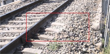
The effect of dynamic loads of moving trains on reducing track deterioration is great. The process of degradation of the rail marks in the transition zone is especially noticeable when shown in Fig. 1, the way the construction of the track is not the same.
Fig. 1The depression that forms close to the bridge as the result of the crushed stone in the ballast layer at the crossing section. The photograph, taken by the second author on August 25, 2025, illustrates issues with the road superstructure in the transition zone from the earthwork to the bridge

4. Results and discussion
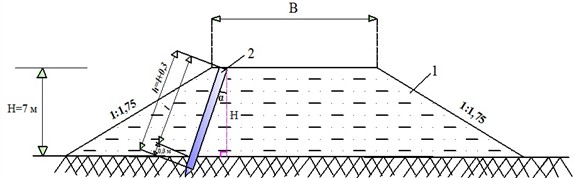
Strengthening the approach embankment bridge soil in front of the shoreline support with piles decreases the active pressure of the soil on the structure, and a part of the impact forces of moving vehicles is transferred directly to the foundation soil. The embankment soil is also compacted when pushing the piles and causes a more uniform dispersal of such stresses across the structure cross-section. The scheme of its calculation is depicted in Fig. 2.
An analogous approach associated with the stability of the embankments, which are built on the relatively weak soil base in the high-speed railway lines, was developed and introduced in [11].
In enhancing the roadbed, piles are used to provide the overall seismic stability of the structure, as this construction is comparatively elastic, the embankment soil is able to deform without collapsing (detailed information in this regard is presented in [12].
The best reinforced concrete piles are the double-T piles; it is significantly lighter than a rectangle pile and its contact area with soil is wide. Two piles will be adequate in the case of a single track railway and three in the case of the railway that are of the dual track.
In a sunk (recessed) condition of the quay support, the friction force is enhanced which gives it stability. Mathematically, the growth in the friction surface when creating the sunk base of the quay support is illustrated in Fig. 3.
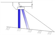
Fig. 2Raised portion of the soil foundation at the approach section in front of the bridge abutment reinforced with piles: 1 – bridge abutment; 2 – reinforced concrete piles; L – length of the piles
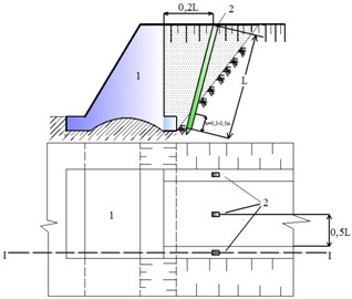
Fig. 3Computation of the extra intersection area of submerged base of the coastal support with the soil: 1 – retaining wall; 2 – counter fortunes; 3 – submerged support surface of the retaining wall; 4 – road subgrade; 5 – excavation areas; 6 – mass of soil in landslides; Ea – active earth pressure
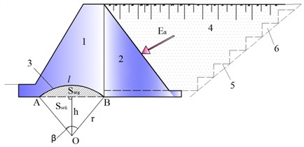
The concave base is partitioned into a segment and circular sector. The sector area is calculated by Eq. (1):
The segment area is calculated with Eq. (2):
where: – radius of a circle, m; – central angle; – area of triangle in a sector, m2; = 3.14.
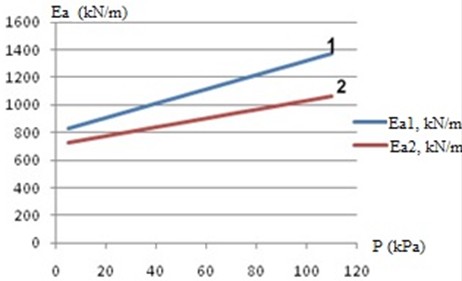
Fig. 4 represents the distribution graph of the active pressure of the embankment soil on the abutment of the bridge by driving reinforced concrete piles into the embankment in the junction zone of the railway roadbed and the bridge.
To enhance the dynamic stiffness of soils around the approaches to bridges, in case the embankment height is 7 m, the distance between reinforced concrete piles driven into dune sandy soils is calculated as follows: In sections with track I, the main area width of the roadbed is 7.6 m; In sections with track II, the main area width is 11.7 m (SHNK 2.05.01-19. Railway design 1520 mm gauge). The quantity of piles to be driven to dampen vibrations in the embankment is calculated by dividing the distance between the reinforced concrete piles.
Fig. 4The active pressure of soil in the area of connection of the railway embankment and the bridge is connected to the uniformly distributed load: 1 – the active pressure of soil acting on the shore support in the area of connection of the railway embankment and bridge after driving the piles; 2 – the active pressure of soil acting on the shore support in the area of connection of the railway embankment and the bridge after driving the piles
The thickness of the reinforced concrete piles striking the support in the region where track bed and the bridge meet is calculated by Eq. (3):
where: – the spacing between reinforced concrete driven piles into the subgrade of a railway, m; – the breadth of the core of the railway treck, 7.6 m; – top of track bed embankment height, 7 m; – dynamic coefficient using the soil properties, in barchan sands 40; – A coefficient taken into account the velocity of trains; – inclination angle of piles, 20°-40°, it is prudent that the value be in this range 20°; – the reinforced concrete piles length, m.
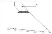
The duration of the reinforced concrete piles is focused on the geometrical method indicated in Fig. 5.
Fig. 5Computational scheme of determining the length of a reinforced concrete pile: 1 – subgrade in the railway; 2 – reinforced concrete pile
The expression for calculating the angle of inclination relative to vertical for a reinforced concrete pile driven to strengthen the earthwork is given in Eq. (4):
The length of the reinforced concrete pile driven to strengthen the ground foundation is calculated using Eq. (5):
Table 2 presents the calculated differences between the reinforced concrete piles that are being driven in the Barxan sand embankment.
Table 2The separability between reinforced concrete piles that were plunged into sandy earth
Single track rail section base of the railway track bed embankment 7 m, width of main area of the railway treck 7.6 m | Two-track railway section railway track bed embankment height 7 m, the dimensions of the primary area of the railway passage 11.7 m | ||
12.6 m | 1.0 | 26.1 m | 1.0 |
12.1 m | 0.95 | 24.9 m | 0.95 |
11.6 m | 0.90 | 23.7 m | 0.90 |
11.1 m | 0.85 | 22.6 m | 0.85 |
10.6 m | 0.80 | 21.4 m | 0.80 |
10.4 m | 0.78 | 20.9 m | 0.78 |
SM-3 oscillograph sensors depicted in Fig. 6 help to reduce vibrations in the embankment in the transition zone and to measure vibrational displacements, vibration velocities, and vibration accelerations of a three-axis coordinate system : The sensors are 3 units to determine vibrational displacements and vibration velocities on the three axis coordinate system .
Fig. 6Vibrations detectors that consider the key parameters of the vibrations on the railway roadbed in 3-axis coordinate system x,y,z. The photograph, taken by the second author on May 19, 2022, provides a general view of seismometric sensors that record the process of vibrations in the earth’s surface
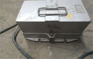

Fig. 7The SM-3 sensors and a vibrator on railroad roadbed in three-axis coordinate system x,y,z. The photograph, taken by the second author on May 19, 2022, depicts the process of installing seismometric sensors on a model (prepared by the second author) designed to record the process of vibrations in the ground surface
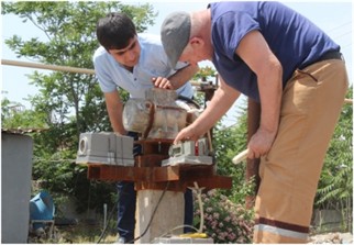
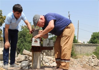
First, a set of three sensors that detect a vibrational displacement in a 3-axis coordinate system , and a VI-9-8A model vibrator is mounted on a reinforced concrete pile driven into the junction point between the railway roadbed and the bridge, as shown in Fig. 7.
Once the sensor and the vibrator have been installed, the vibrator is turned on and the vertical load on the reinforced concrete pile is 11.3 kN. Due to this vibration, each sensor undergoes different oscillations relative to the three-axis coordinate system and they are measured on a computer. Fig. 8 shows the results obtained.
Fig. 9 shows the seismograms of all the detected cases with the help of the sensors.
Fig. 8The recording vibrations that take place in the railway roadbed using SM-3 sensors on the computer. The photograph taken by the second author on May 19, 2022, shows the process of recording ground vibrations using a computer program
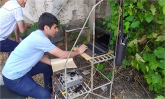

Fig. 9a) Seismogram at SM-3 sensors mounted in the soil at the edge of the embankment and b) slope of the junction area between the railway roadbed and the bridge with the vibrator off
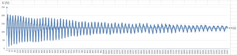
a)
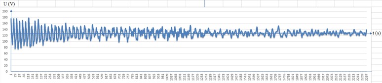
b)
The amplitude of vibration in the embankment soils at the junction areas between the railway roadbed and the bridge are calculated using Eq. (6) depending on the amplitude values of the recorded seismograms:
where: – maximum amplitude in the seismogram that was recorded (mm), – the highest point on the recorded seismogram (mm).
After processing the results of the carried out experiment, it was established that the amplitude of the vibrations in the soils of the embankment decreased, the period of the specific vibrations of the railway roadbed decreased by 15 percent, the velocity of the vibrations and the movement of vibration decreased by 10 percent and 15 percent, respectively. Consequently, reduction in logarithmic decrement of vibrations up to 20 percent was noted. The settlement of the railway roadbed and prism of the ballast is on the average 15 sm per three months; when the piles are laid in to strengthen the foundation the settlement is 5-7 sm. This, in turn, assists in halving the expenses of the railway track maintenance and enhances the capacity to retain the track in a safe and functioning state, free of mishaps.
5. Conclusions
1) It has been scientifically proven that the value of seismic and vibrodynamic forces significantly increases due to the high specific weight of existing reinforced concrete boxes and slabs used for strengthening transition sections. The reinforcement method we have developed, namely the technology of driving reinforced concrete piles, is easy to implement and, due to its low specific weight, results in a significantly lower seismic force value. This serves as a basis for preventing deformations in the transition section.
2) Due to the implementation of the suggested technology, the active pressure on the shore support of the bridge caused by weighting of the soil layer and a vibrodynamic force of the moving mass is decreased by 12 %.
3) By driving reinforced concrete piles into the embankment through the developed reinforcement technique, the dynamic stiffness of the soil foundation improves, the soil is more compacted, and the internal friction angle of the soil also increases sharply. Consequently, owing to redistributing part of the vertical stresses on the embankment on the foundation in the transition zone between the embankment and the bridge, the stress in the embankment soil decreases.
4) The optimization of designing like this, the transition section of the crossing part of the ground slab to a bridge, increases the friction section on the support, compared with a straight-line foundation by 8-12 percent owing to the concavity (circular sector and segment) configuration of the support, providing it with an extension of service life.
6. Future scope
High-level Material Integration: Future studies can consider incorporating new material types of composite material reinforcement piles like the fiber-reinforced polymers (FRP) to further increase soil stiffness and stability during dynamic loading.
Real-Time Monitoring Systems: Embarkation and bridge foundation smart sensor technologies can be put in place to provide real-time data on soil pressure, vibration, and settlement, which can be used to perform proactive maintenance and optimization.
Machine Learning to predictive analysis: Predicting the behaviour of soil and foundation interaction under different dynamic loads by using machine learning models has the potential to enhance the accuracy of design and the lifespan prediction of bridge supports.
Environmental Impact Assessment: The extension of the study to examine the environmental impact of soil reinforcement methods, especially the consequences on the groundwater flow and ecology of the soil to guarantee sustainable construction practices.
Optimization of Vibrodynamic Mitigation Techniques: Addition of vibrodynamic force mitigation techniques such as active damping systems might minimise vibrations that are passed to the bridge structure and soil around it.
Application to Seismic Zones: The study of the application of reinforcement and foundation optimization methods to seismic prone areas in order to enhance earthquake resistance as well as minimize structural damage.
Long-Term Durability Tests: Testing on the reinforced embankments should be performed to investigate the performance deterioration, soil-structure interaction modifications, and the reinforcing efficiency on decades.
Automation in Pile Installation: The development of automated and robotic controlling in the driving of reinforced concrete piles with high accuracy to save and shorten the time of installation and enhance uniformity in foundation reinforcement.
References
-
H. Wang and V. L. Markine, “Analysis of the long-term behaviour of track transition zones,” in The Third International Conference on Railway Technology: Research, Development and Maintenance, Vol. 110, pp. 203–220, Jul. 2025, https://doi.org/10.4203/ccp.110.203
-
K. S. Lesov and M. K. Kenjaliyev, “Organizational and technological parameters during the construction of the Bukhara-Misken railway line,” in AIP Conference Proceedings, Vol. 2432, p. 03002, 2022, https://doi.org/10.1063/5.0087750
-
K. Lesov, M. Kenjaliyev, A. Mavlanov, and S. Tadjibaev, “Stability of the embankment of fine sand reinforced with geosynthetic materials,” in E3S Web of Conferences, Vol. 264, p. 02011, Jun. 2021, https://doi.org/10.1051/e3sconf/202126402011
-
H. Wang and V. Markine, “Corrective countermeasure for track transition zones in railways: Adjustable fastener,” Engineering Structures, Vol. 169, pp. 1–14, Aug. 2018, https://doi.org/10.1016/j.engstruct.2018.05.004
-
A. Abdujabarov, M. Mekhmonov, P. Begmatov, F. Eshonov, and M. Khamidov, “Consideration of the environmental impact on the seismic inertial forces of the railway track in difficult conditions,” in Problems in the Textile and Light Industry in the Context of Integration of Science and Industry and Ways to Solve Them: PTLICISIWS-2, Vol. 3045, p. 030097, Jan. 2024, https://doi.org/10.1063/5.0197332
-
G.-A. Khalfin, K. Umarov, I. Purtseladze, and M. Yembergenov, “System for determining state of continuous welded track,” in E3S Web of Conferences, Vol. 401, p. 02050, Jul. 2023, https://doi.org/10.1051/e3sconf/202340102050
-
M. Mekhmonov and A. Uralov, “Reducing impact of embankment soils on shore support of bridge on the approaches to bridges,” in E3S Web of Conferences, Vol. 401, p. 02040, Jul. 2023, https://doi.org/10.1051/e3sconf/202340102040
-
S. Hodas, J. Izvoltova, J. Chromcak, and D. Bacova, “Monitoring the geometric position of transition zones to increase the quality and safety of railway lines,” Applied Sciences, Vol. 12, No. 12, p. 6038, Jun. 2022, https://doi.org/10.3390/app12126038
-
M. Esmaeili, H. Heydari-Noghabi, and M. Kamali, “Numerical investigation of railway transition zones stiffened with auxiliary rails,” Proceedings of the Institution of Civil Engineers – Transport, Vol. 173, No. 5, pp. 299–308, Oct. 2020, https://doi.org/10.1680/jtran.17.00035
-
Y. Shan, S. Zhou, B. Wang, and C. L. Ho, “Differential settlement prediction of ballasted tracks in bridge-embankment transition zones,” Journal of Geotechnical and Geoenvironmental Engineering, Vol. 146, No. 9, p. 04020, Sep. 2020, https://doi.org/10.1061/(asce)gt.1943-5606.0002307
-
M. Mekhmonov, S. Makhamadjonov, and A. Uralov, “Efficiency of reinforcement of transition sections on the railroad by the developed constructions,” in E3S Web of Conferences, Vol. 508, p. 08017, Apr. 2024, https://doi.org/10.1051/e3sconf/202450808017
-
M. Mekhmonov and S. Makhamadjonov, “Investigation of the period of natural oscillations of the embankment on approaches to bridges,” in E3S Web of Conferences, Vol. 401, p. 05032, Jul. 2023, https://doi.org/10.1051/e3sconf/202340105032
About this article

The authors have not disclosed any funding.
The datasets generated during and/or analyzed during the current study are available from the corresponding author on reasonable request.
The authors declare that they have no conflict of interest.
