Abstract
The working elements of agricultural and road construction machinery operating in abrasive environments often fail prematurely due to intense wear. Enhancing their wear resistance is therefore a pressing challenge. This scientific article presents the results of laboratory, bench, and field tests of undercarriage components of tracked machines, whose working surfaces were strengthened with wear-resistant coatings. Borided and boro-titanized coatings were formed on the working surfaces of the support and drive rollers, while composite bimetallic coatings based on PG-S27 “Sormite” with the addition of boron carbide were applied to the running surfaces of track links directly during casting. Numerous tests have demonstrated that the developed technologies for forming wear-resistant coatings on the friction surfaces of tracked machine undercarriage parts increase their wear resistance by a factor of 5 to 7. This represents an effective solution to one of the most critical operational challenges for machinery working under conditions of severe abrasive wear.
Highlights
- A method for enhancing the wear resistance of components has been developed and is proposed, which is implemented directly during the casting process.
- The wear resistance of coatings formed directly on the surface of components during the casting process was comprehensively investigated under laboratory conditions, on specialized test rigs, as well as under real operating conditions.
- To ensure the reliability of the results, the number of samples was increased—each pair consisted of five sets.
- Prior to testing, throughout its duration, and upon completion, a comprehensive assessment was conducted, including measurements of sample mass (linear wear) as well as analysis of microstructural and microgeometric changes in the friction surfaces.
- The analysis of the results obtained from comprehensive testing demonstrates that the developed technologies for enhancing the wear resistance of undercarriage components in tracked vehicles make it possible to increase the wear resistance of the entire undercarriage assembly by a factor of 5–7.
1. Introduction
The working elements of agricultural and road construction machines operating under contaminated and abrasive conditions are subjected to intensive wear, which leads to their premature failure. Enhancing the wear resistance and durability of such components is an important challenge faced by engineers and researchers in the field of mechanical engineering [1-3].
A variety of methods have been developed and are currently employed to improve the wear resistance and durability of machine parts operating in abrasive environments, such as hardfacing [4, 5], thermal spraying [6], surface hardening [7, 8], chemical-thermal treatment [9, 10], surface alloying [11], and others.
It is well known that the main components of the undercarriage of tracked road construction machines – such as track links, support rollers, and drive sprockets – operate under severe abrasive conditions, which cause their intensive wear and lead to premature failure before the end of their designated service life.
The service life of the main components of the undercarriage of single-bucket tracked excavators (support rollers, drive wheels, and track links) generally does not exceed 1000-1500 operating hours [1, 2]. The primary reason for such a limited service life is the intensive abrasive wear of undercarriage components, which occurs during machine operation under severe soil conditions. As a result of the intensive wear of the working surfaces of these components, their operational reliability is significantly reduced, leading to increased maintenance and repair costs.
According to the data reported in [2, 3], the service life of single-bucket excavators before major overhaul is approximately 5000-6000 operating hours. This value is considered an indicative normative service life for the undercarriage components of tracked machines operating under conditions of intensive abrasive wear.
As emphasized in many studies, improving the wear resistance of friction pair components operating under conditions of loose abrasive media requires a comprehensive approach [4, 5]. This problem cannot be solved solely by increasing the durability of individual elements. In this regard, an important task is to enhance the overall wear resistance of all components of the tracked propulsion system – including track links, support and drive wheels, and other parts – in order to ensure the durability and reliability of the system as a whole.
At present, various technological methods aimed at improving the wear resistance of machine components have been developed and are being applied in practice [9-12]. In the present study, a method for improving the wear resistance of machine components, implemented directly during the casting process, has been developed and proposed. This constitutes the scientific novelty of the research. The proposed approach is characterized by economic efficiency, technological simplicity, and the absence of any need for expensive equipment [11-12]. This method, being a cost-effective and highly efficient solution, can be successfully applied to strengthen the working surfaces of components used in road construction and agricultural machinery [13-15].
Research Objective: To carry out laboratory and field tests on the abrasive wear of the undercarriage components of an excavator with various combinations of wear-resistant coatings.
2. Main theoretical section
The wear resistance of coatings formed directly during the casting process on the surface of components was comprehensively studied both under laboratory conditions and in real operating environments. The conducted investigations made it possible to evaluate the reliability and operational stability of the formed coatings.
2.1. Methodology of laboratory testing
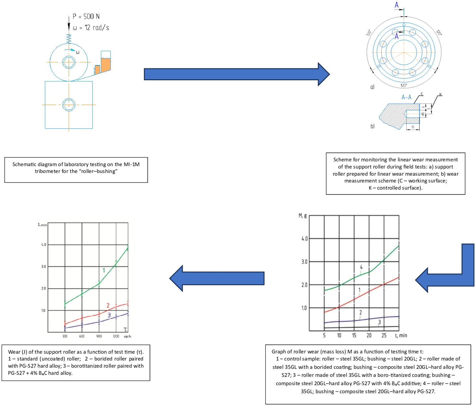
The assessment of the wear resistance of components operating in frictional pairs under abrasive conditions was conducted using the MI-1M tribological testing machine. During the experiments, abrasive particles were continuously introduced into the contact zone by means of a specially engineered dosing device (Fig. 1). The laboratory tests were structured according to a configuration that closely reproduced the interaction between the track roller and the track link and, to a somewhat lesser extent, the contact conditions of the drive wheel-track link pair of crawler-type road construction machinery (Fig. 1). This configuration also reflects the actual operating conditions of the undercarriage of crawler agricultural equipment. Such an experimental design ensured the validity of the results and their high degree of correspondence to real service environments.
In the “roller-bushing” configuration, the roller was positioned at the top and the bushing at the bottom. The test specimen (roller), mounted in the upper position, was driven into rotational motion by an electric motor. The rotation speed could be adjusted by replacing the gear wheels. The roller had a diameter of 42 mm and a width of 12 mm (Fig. 2(a)).
The bushing specimen, mounted in the lower part of the setup, remained stationary. The roller positioned above was pressed against the bushing by means of a spring, generating a specified load. The load could be adjusted up to 500 N and was monitored using a scale. The dimensions of the bushing were 50×50×10 mm (Fig. 2(b)). During the tests, the roller slid over the surface of the bushing at a sliding speed of 0.25-0.27 m/s.
Each specimen was tested for 30 minutes. Every 5 minutes, the test was paused and the mass of the specimens was measured using HERMES laboratory electronic scales. Before weighing, the specimens were rinsed in gasoline and air-dried. The wear rate was assessed based on the reduction in the specimen mass.
Abrasive particles were supplied to the friction zone using a specially designed dosing device. The abrasive feed rate was 10 g/min. Quartz sand of grade 1K02A (GOST 22551-77) was used as the abrasive medium.
The laboratory tests were conducted according to the variants presented in Table 1. To ensure the reliability of the results, the number of specimens was increased – each test pair consisted of 5 sets.
In order to most accurately reproduce the operating conditions of the crawler undercarriage of road-building machinery, the test specimens were manufactured from the same steel grades as those used in actual structural components of the machines. In particular, the rollers were produced from 35GL steel, corresponding to the track-supporting rollers and drive wheels, while the bushings were made from 20GL steel, analogous to the track links. Furthermore, the casting technology applied in the fabrication of the specimens was consistent with that used in industrial practice: thus, the rollers were cast using the lost-foam casting method, whereas the bushings were produced in conventional sand–clay molds. This approach ensured the proximity of the testing conditions to real operational service and allowed for a reliable evaluation of the obtained results.
Fig. 1Schematic diagram of laboratory testing on the MI-1M tribometer for the “roller–bushing” pair: 1 – roller; 2 – bushing; 3 – quartz sand; 4 – container; 5 – dosing unit
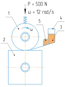
Fig. 2Roller and bushing configurations for laboratory testing: roller (support roller model) and bushing (track link model)
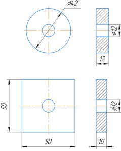
Table 1Laboratory test variants
Set No | Roller processing variant | Bushing processing variant | Number of tests |
Control | 35GL steel | 20GL steel | 5 |
I | 35GL steel | Bimetallic joint of 20GL steel and PG-S27 alloy | 5 |
II | Borided | Bimetallic joint of 20GL steel and PG-S27 alloy | 5 |
III | Borotitanized | Bimetallic joint of 20GL steel and PG-S27 +4%В4С alloy | 5 |
Before, during, and after the tests, a comprehensive assessment was carried out, including mass measurements of the specimens as well as analysis of microstructural and microgeometric changes in the friction surfaces. The specimen mass was measured with high precision using HERMES lelectronic scales with an accuracy of 0.001 mg. The microstructure of the surfaces and the nature of changes occurring in the friction zones were examined using an OLYMPUS BXM 41 optical microscope.
The microgeometric parameters of the specimen surfaces were determined using a TR-300 profilograph-profilometer in accordance with GOST 2789-73. The tests were conducted under the following conditions: sensor feed rate – 6 mm/min, chart speed – 600 mm/min, and scanning step – 0.25 mm. During measurements, the vertical magnification was ×500 and the horizontal magnification was ×100. The surface roughness profile of the friction surfaces was determined from profilograms taken in a direction perpendicular to the sliding direction.
2.2. Methodology of field testing
Field tests were aimed at evaluating the wear resistance of undercarriage components of tracked machines under real operating conditions. For this purpose, two identical tracked machines were selected, with their undercarriages equipped with different variants of structural components.
One of the machine’s tracks was equipped with standard components – track links, support wheels, and drive wheels – that had not undergone any surface hardening treatment. The second track, serving as the experimental group, was fitted with components featuring enhanced wear resistance achieved through the application of wear-resistant coatings.
Thus, the undercarriage of each machine was assembled using components with different operational characteristics: in one case – traditional components (control group), and in the other – components with wear-resistant coatings (experimental group). This approach enables a direct comparison of the effectiveness of different technological solutions.
Before the start of testing, each component was marked using the electrographic method to ensure accurate wear tracking. During measurements, the wear on each part was recorded using measuring instruments at predefined control points.
The linear wear of the support roller was measured according to the scheme shown in Fig. 3. For this purpose, prior to testing, three holes with a diameter of 6 mm and a depth of 10 mm were drilled along the perimeter of the roller’s working surface. The holes were positioned at 120° intervals from each other and located 9 mm from the roller edge (Fig. 3).
The amount of wear was monitored by measuring the distance between the working surface of the roller and the centers of the drilled holes (Fig. 3(b)).
Fig. 3Scheme for monitoring the linear wear measurement of the support roller during field tests: a) support roller prepared for linear wear measurement; b) wear measurement scheme (C – working surface; K – controlled surface)
a)
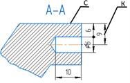
b)
Fig. 4Scheme for monitoring the linear wear of the track link during field tests
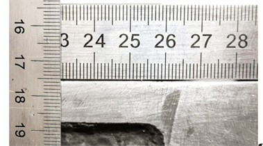
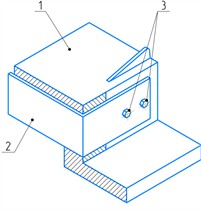
Fig. 5Scheme for monitoring the linear wear of the drive wheel teeth using a template during field tests: 1 – drive wheel tooth; 2 – template; 3 – fastening bolts
The linear wear of the working surface of the track link was monitored according to the scheme shown in Fig. 4.
The wear of the working surfaces of the drive wheel was monitored according to the scheme shown in Fig. 5, using a template by measuring the gap between the template and the working surface of the drive wheel.
3. The main experimental section
3.1. Laboratory test results
The evaluation of the wear resistance of friction pair surfaces under conditions of free abrasive environment was carried out based on laboratory tests. The obtained results are presented in Figs. 6-8. During the tests, the mass of the samples was periodically measured, which made it possible to monitor the dynamics of the wear process over time.
In particular, Fig. 6 presents a graph illustrating the wear of the roller surface as a function of time. The graph clearly reflects both the rate and nature of the wear process, expressed through the progressive reduction in the mass of the samples as the test duration increases.
This graph clearly demonstrates the influence of abrasive particles on the sliding surface and enables the assessment of material wear rate. It is particularly evident that during the initial stage of testing, the wear is intensive, after which it gradually stabilizes. Such behavior may be attributed to changes in the surface microstructure, stabilization of frictional conditions, or surface layer hardening resulting from plastic deformation and the subsequent balancing of wear mechanisms.
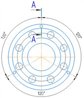
Fig. 6Graph of roller wear (mass loss) M as a function of testing time t: 1 – control sample: roller – steel 35GL; bushing – steel 20GL; 2 – roller made of steel 35GL with a borided coating; bushing – composite steel 20GL-hard alloy PG-S27; 3 – roller made of steel 35GL with a boro-titanized coating; bushing – composite steel 20GL-hard alloy PG-S27 with 4 % B4C additive; 4 – roller – steel 35GL; bushing – composite steel 20GL–hard alloy PG-S27
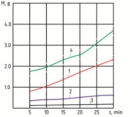
Fig. 7Graph of bushing wear (mass loss) M as a function of testing time t: 1 – control sample: bushing – steel 20GL; roller – steel 35GL; 2 – bushing – composite steel 20GL–hard alloy PG-S27; roller made of steel 35GL with a borided coating; 3 – bushing – composite steel 20GL–hard alloy PG-S27 with 4 % B4C additive; roller made of steel 35GL with a boro-titanized coating; 4 – bushing – composite steel 20GL–hard alloy PG-S27; roller – steel 35GL
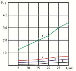
Fig. 8Graph of total wear (mass loss) M of the roller-bushing pair as a function of testing time t: 1 – control sample: roller – steel 35GL; bushing – steel 20GL; 2 – roller made of steel 35GL with a borided coating; bushing – composite steel 20GL-hard alloy PG-S27; 3 – roller made of steel 35GL with a boro-titanized coating; bushing – composite steel 20GL-hard alloy PG-S27 with 4 % B4C additive; 4 – roller – steel 35GL; bushing – composite steel 20GL–hard alloy PG-S27
As shown in the graph in Fig. 6, the wear in the control roller pair (curve 1) is the most intensive. In the samples with a borided surface (curve 2), the wear rate is significantly reduced, and in rollers with a boro-titanized coating (curve 3), the reduction is even more pronounced. When using the “roller with borided surface – bushing made of hard alloy composition 20GL steel – PG-S27” pair, the wear resistance increased by a factor of 3-4. In the case of the “boro-titanized roller – bushing made of 20GL steel – PG-S27 + 4 % B4C” pair, the wear resistance improved by 7-12 times.
The most intensive wear was observed in the pair consisting of a roller made of 35GL steel and a bushing made of hard-alloy composition 20GL steel – PG-S27 (curve 4 in Fig. 6). In this case, the wear of the roller was 1.6 times higher compared to the control pair (curve 1).
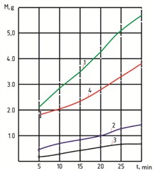
The wear dynamics of the bushing in the control pair (curve 1 in Fig. 7) were even more pronounced compared to the roller (curve 1 in Fig. 6). In the pair where the roller was made of borided 35GL steel and the bushing was made of a hard-alloy composition of 20GL steel – PG-S27, the wear resistance increased by 3.5-4.0 times (curve 2 in Fig. 7). When a composite based on 20GL steel – PG-S27 with the addition of 4 % boron carbide (B4C) was used, wear resistance increased by 7-8 times (curve 3 in Fig. 7).
Analysis of curve 4 in Fig. 7 shows that the lowest wear intensity is observed in the pair consisting of a bushing made of the hard-alloy composite 20GL steel – PG-S27 and a roller made of 35GL steel without a wear-resistant coating. This material combination exhibits the highest wear resistance among all the variants studied.
The total wear of the roller–bushing pair under the influence of free abrasive particles is presented in Fig. 8. The most intensive wear is observed in the control pair (roller – 35GL steel, bushing – 20GL steel), as shown by curve 1. In the pair where the roller with a borided coating operates with a bushing made of the composite hard alloy 20GL steel – PG-S27 (curve 2), the wear resistance is 4-5 times higher compared to the control pair. The best wear resistance is demonstrated by the pair consisting of a roller with a borotitanized coating and a bushing made of 20GL steel – PG-S27 composite with the addition of 4 % boron carbide; its total wear is almost 10 times lower than that of the control pair (curve 3). Although the wear resistance of the pair represented by curve 4 (roller – 35GL steel, bushing – 20GL steel – PG-S27) is inferior to the coated variants, it still exceeds that of the control pair (curve 1).
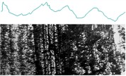
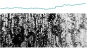
Fig. 9Profilogram and microstructure of the control roller–bushing pair after laboratory tests (magnification: horizontal – ×100, vertical – ×500) and surface microstructure (×100): a) roller made of 35GL steel; b) bushing made of 20GL steel
a)
b)
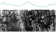
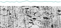
Fig. 10Profilogram and microstructure of the roller–bushing pair consisting of a borided steel roller and a bushing made of hard alloy composite (20GL steel – PG-S27), after laboratory tests (magnification: horizontal – ×100, vertical – ×500), and surface microstructure (×100): a) roller – 35GL steel with borided coating; b) bushing – composite of 20GL steel with hard alloy PG-S27
a)
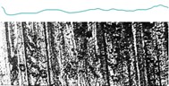
b)
The microstructure and microgeometry of the friction surfaces were analyzed based on the results presented in Fig. 9 and 10. According to the obtained data, the wear pattern undergoes significant changes when transitioning from control samples to surfaces with borided and borotitanized coatings. In particular, the surfaces of the control samples exhibit clear signs of severe degradation, including deep plastic deformation, micro-cutting, and material pull-out (Fig. 9(a) and 10(a)). In contrast, the borided surfaces show less aggressive wear, characterized mainly by barely visible scratches oriented parallel to the sliding direction (Fig. 9(b) and Fig. 10(b)). This indicates an increase in surface layer hardness due to boriding and, consequently, enhanced resistance to abrasive wear.
The microstructure and microgeometry of the friction surfaces complement and reinforce each other (Fig. 10). Specifically, the surfaces of the control samples that underwent full testing exhibit pronounced large-scale microroughness (Fig. 9), whereas the surfaces with wear-resistant coatings show only minor topographical changes (Fig. 11).
Fig. 11Profilogram and microstructure of the roller–bushing pair consisting of a borotitanized steel roller and a bushing made of hard alloy composite (20GL steel – PG-S27 + 4 % B4C), after laboratory tests (magnification: horizontal – ×100, vertical – ×500), and surface microstructure (×100):a) roller – 35GL steel with borotitanized coating; b) bushing – composite of 20GL steel with hard alloy PG-S27 + 4 % B4C
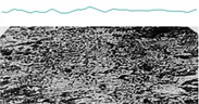
a)
b)
4. Field test results
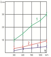
The results of the field tests are presented in Fig. 12, 13, and 14, which illustrate the wear dynamics of the working surfaces of components both with and without wear-resistant coatings.
Curve 1 in Fig. 12, 13, and 14 represents the wear of components with untreated working surfaces; curve 2 corresponds to the wear of the pair consisting of a borided support roller and a track link made of a composite hard alloy based on 20GL steel – PG-S27; curve 3 reflects the wear of the pair consisting of a borotitanized support roller and a track link made of composite alloy 20GL – PG-S27 + 4 % B4C.
As shown in the graphs, an intensive increase in wear begins after 900 operating hours on the support roller (Fig. 12, curve 1), after 600 hours on the track link (Fig. 13, curve 1), and between 600-900 hours on the drive wheel (Fig. 14, curve 1).
For components with wear-resistant coatings, the limiting wear values were not observed (curves 2 and 3 in Figs. 12-14). Moreover, the wear resistance of the first pair improved by 3.0-4.5 times, and the second pair by 5-7 times (Figs. 12-14).
Fig. 12Wear (J) of the support roller as a function of test time (τ): 1 – standard (uncoated) roller; 2 – borided roller paired with PG-S27 hard alloy; 3 – borotitanized roller paired with PG-S27 + 4 % B4C hard alloy
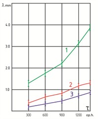
Fig. 13Wear (J) of the track link as a function of test time (τ): 1 – standard (uncoated) link; 2 – link with hard coating of PG-S27 alloy paired with borided roller; 3 – link with hard coating of PG-S27 + 4 % B4C alloy paired with borotitanized roller
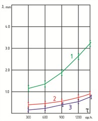
Fig. 14Wear (J) of the drive wheel as a function of test time (τ): 1 – standard (uncoated); 2 – borided; 3 – borotitanized
5. Conclusions
A technological approach for the formation of borided and borotitanized coatings on the working surfaces of support rollers and drive wheels, as well as bimetallic composite coatings based on the PG-S27 alloy with the addition of boron carbide (B4C) on the surfaces of track links, has been developed and experimentally substantiated. A distinctive feature of the proposed method is the formation of a strengthened surface layer directly during the casting process, which makes it possible to significantly increase the hardness of the working surfaces and their resistance to abrasive wear. It has been established that the application of the developed coatings increases the wear resistance of the undercarriage components of tracked machines operating in friction pairs by an average of 5-7 times compared with conventional components.
The practical significance of the obtained results lies in the possibility of implementing the proposed technology in the production of cast components for road construction and agricultural machinery. The implementation of the developed approach makes it possible to significantly increase the service life of the most heavily loaded undercarriage components, improve the operational reliability of machinery operating under conditions of intensive abrasive wear, and reduce maintenance and repair costs.
References
-
A. K. Reish, Improving the Wear Resistance of Construction and Road Machines. Moscow: Mashinostroenie, 1986.
-
A. K. Reish and V. G. Berdnikov, “Causes of wear of undercarriage components of single-bucket excavators and ways to extend their service life,” Construction and Road Machines, No. 3, pp. 13–22, 1965.
-
B. N. Orlov, V. A. Evgrafov, and N. B. Orlov, “Durability of working parts of soil-cultivating machines,” Mechanization and Electrification of Agriculture, No. 3, pp. 27–29, 2007.
-
A. A. Parkin, S. S. Zhatkin, and E. A. Minakov, “Optimization of plasma surfacing technology for powder materials,” Metallurgy of Mechanical Engineering, No. 1, pp. 44–49, 2011.
-
A. V. Sobachkin, A. A. Sitnikov, V. I. Yakovlev, M. E. Tatarkin, M. V. Loginova, and M. N. Seydurov, “Improving the wear resistance of working parts of agricultural machines by electric arc surfacing with a powder electrode,” Polzunovsky Almanac, Vol. 4, No. 2, pp. 133–136, 2011.
-
V. V. Kudinov and G. V. Bobrov, Deposition of Coatings by Spraying: Theory, Technology, and Equipment. Moscow: Metallurgy Publishing, 1993.
-
V. R. Edigarov, “Classification of combined processing methods based on electromechanical hardening,” Modern High Technologies, No. 3, pp. 32–36, 2012.
-
Y. K. Mashkov, V. R. Edigarov, M. Y. Baybaratskaya, and Z. N. Ovchar, “Combined friction-electric modification of steel friction surfaces,” Friction and Wear, Vol. 27, No. 3, pp. 89–92, 2006.
-
L. G. Voroshnin, O. L. Mendeleeva, and V. A. Smetkin, Theory and Technology of Thermo-Chemical Treatment. Moscow: Novoe Znanie, 2010.
-
V. E. Gromov et al., “Structure and properties of wear-resistant coatings welded onto steel by arc method using cored wires,” Advances in Physics of Metals, Vol. 15, pp. 211–232, 2014.
-
M. A. Guryev, S. G. Ivanov, and E. V. Chernykh, “Surface alloying of parts during their manufacturing by the casting method using gasified patterns,” Fundamental Problems of Modern Materials Science, Vol. 12, No. 4, pp. 429–431, 2015.
-
S. Z. Yunusov, S. A. Makhmudova, D. A. Kasimova, and M. M. Agzamov, “The influence of changes in technological loads on the deflection of the saw cylinder shaft of a linting machine,” Material and Mechanical Engineering Technology, No. 1, pp. 2–13, Mar. 2025, https://doi.org/10.52209/2706-977x_2025_1_8
-
M. G. Krukovich, B. A. Prusakov, and I. G. Sizov, Plasticity of Borided Layers. Moscow: Fizmatlit, 2010.
-
N. Bekmurzaev, F. Norkhudjaev, and S. Alimukhamedov, “Energy aspects of conjugated heterophase surfaces wear operating in a free abrasive medium,” in Problems in the Textile and Light Industry in the Context of Integration of Science and Industry and Ways to Solve Them: PTLICISIWS-2, Vol. 3045, p. 060018, Jan. 2024, https://doi.org/10.1063/5.0197469
-
N. Bekmurzaev, K. Nurmetov, and S. Alimukhamedov, “Creation of a wear-resistant bimetallic coating for the track treadmill of a crawler,” Vibroengineering Procedia, Vol. 60, pp. 370–377, Dec. 2025, https://doi.org/10.21595/vp.2025.25613
About this article

The authors have not disclosed any funding.
The datasets generated during and/or analyzed during the current study are available from the corresponding author on reasonable request.
The authors declare that they have no conflict of interest.
