Abstract
In this article, the application of numerical methods to determine the magnetic field parameters of traction motors operating on Uzbekistan's railways allows us to characterize their design features, which is necessary to complement existing mathematical models and determine the efficiency of traction motors as energy converters. The magnetic field vector potentials of traction motors under local conditions are calculated, including those of high-speed electric rolling stock, subway cars, electric locomotives, diesel locomotives, and a number of foreign models. Design and operational features are discussed, and comparative tables are provided.
1. Introduction
A magnetic field is one of the four fundamental force fields found in nature. Electric charges and magnetic moments act on substances regardless of their motion. Physical substances around which a magnetic field arises include magnetized bodies, current-carrying conductors, and moving electrically charged bodies. In all cases, a magnetic field is generated by the motion of small charged particles and the intrinsic magnetic moment of these particles [1, 4].
One graphical way to represent a magnetic field is to create a magnetic field pattern – magnetic field lines or equipotential lines of vector magnetic potential that describe this field. At each point along such a line, the magnetic induction vector B touches it [2, 3].
In general, a magnetic field is one side of an electromagnetic field, which is generated by the electric charges of moving particles and bodies and by changes in the electric field. Beyond its structure, the magnetic field itself manifests itself as a force acting on charged particles moving relative to it [6, 7]. The magnetic induction vector field has no divergence (there are no sources or sinks, and the magnetic induction lines form continuous, closed circuits) [8, 10].
The widespread use of electromagnetic processes for the conversion, study, construction, and calculation of electromechanical energy is necessary and important, as a magnetic field achieves a significantly higher energy concentration than an electric field [5, 12]. In electromechanical systems, this energy creates significant potential for use in human economic activity. Due to this property, according to [9,11] (up to 20,000 kWh per person per year), virtually all electrical energy is generated by electromechanical energy converters – generators (operating in thermal, nuclear, wind, and hydroelectric power plants), and approximately 60-70 % of the resulting energy is converted into mechanical energy using reversible mechanical motors [12, 13].
The interaction of substances, physical bodies, and electric currents in a magnetic field occurs due to the presence of magnetic dipoles, which can be calculated and represented as magnetic (faradic) tubes or magnetic circuits. Many renowned scientists have studied and described electromagnetic, magnetic, and electric fields, including M. Faraday, E. Lenz, H. Oersted, B. Jacobi, D. Maxwell, D. Henry, and others [9, 19, 20].
The purpose of this study is to characterize the TEM parameters of the magnetic pulsations of the electric motor based on the field-critical equation. The calculation is carried out using numerical modeling for the vector magnetic potential – .
The differential equation is reduced to a discrete form based on the finite element method (FEM) for numerical solution of the model. In this case, the Laplace operator is obtained using numerical differential expressions for the nodes [14-16]:
As a result, the equation is written in the following numerical form:
This expression is written for each node of the grid , forming a system of linear algebraic equations over all nodes.
In numerical modeling of the magnetic induction vector B and the magnetic vector potential Arot, these differential expressions are discretely represented using the finite difference method (FDM) or the finite element method (FEM).
The computational domain is divided into ×× nodes by a grid, in which the components , , of the vector potential are determined at each node.
In the finite difference method, the derivatives are approximated as follows:
Using similar expressions, the values of , , at each node are calculated.
Through this approximation process, the continuous electromagnetic field is converted into a discretized numerical model, and in subsequent stages these values are used to analyze energy, induction or flux density.
The simulation was carried out in the following stages:
1) Material parameters (magnetic permeability , current density ) and boundary conditions were entered as initial data.
2) The computational domain was divided into finite elements, and discrete equations were formulated for each element.
3) The resulting system of linear algebraic equations was calculated using iterative solution methods (Gauss-Seidel or conjugate gradient).
4) The condition (where 10-4-10-6) was set as the convergence criterion of the iterative process.
5) In the final stage, the spatial distribution of magnetic induction and electromagnetic field was determined based on the numerical values of the vector potential .
The developed numerical model allows to determine the distribution of the electromagnetic field in complex geometries, to evaluate the influence of material parameters, and to determine the optimal operating modes. The model also provides solutions that are more accurate, stable, and computationally efficient than analytical approaches.
It is necessary to study the magnetic field induction, and therefore the most significant element in the calculations is determining the magnetic field in a non-stationary mode under changing boundary conditions, i.e., in a mode in which the electric motor anchor rotates. In addition, when calculating the distribution pattern of equipotential lines of vector magnetic potential, the following factors must be taken into account:
– Changes in the relative position of the armature relative to the stationary parts of the magnetic system.
– Displacement of the commutation zone relative to the neutral.
– Asymmetry of air gaps between the structural elements of the electric motor.
2. Methodology
This article examines the magnetic systems of traction motors (TEM) in the most common models of diesel locomotives, electric locomotives, and electric trains operating in the republic: the VL 80S electric locomotives, EP9E electric trains, and UzTE16M2 diesel locomotives.
The VL 80S electric locomotive, with step-voltage regulation and rheostatic braking, is designed for operation on mainline railways electrified with single-phase alternating current (AC) at 27,000 V. The locomotive consists of two sections and can operate in a multi-unit system. The traction motor is an NB-514 pulsating electric motor. The main technical specifications are taken from [20, 21] and are presented in Table 1.
The two-section UzTE16M2 diesel locomotive is designed for freight transportation on non-electrified main lines. The design utilizes an electric traction device [21, 22]. Asynchronous DC traction motors of the ED-118B series are used as traction electric motors.
It has four main and four auxiliary poles, and the anchor has 54 slots. The electric motor output is 305 kW, as shown in Table 1.
Table 1Main technical specifications of the VL 80S and UzTE16M2 electric locomotives
Key indicators | Electric locomotive | Locomotive |
VL 80S | UzTE16M2 | |
Total weight, t | 192 | 2×138 |
Traction system length across coupler axes, mm | 32840 | 16969 |
Total power, kW | 6520 | 2×2206 |
Nominal voltage, V | 27000 | – |
Design speed, km/h | 110 | 100 |
Number of electric motors, units | 8 | 8 |
Traction motor model | NB-514 | ED-118B |
To develop the criteria equation, mathematical models of the NB-514 and ED-118B rotary electric motors were constructed. The distribution patterns of the equipotential lines of the vector magnetic potential for each model are shown in Fig. 1 and 2 [23].
Fig. 1Equipotential lines of the vector magnetic potential and the distribution of induction of the TED model NB-514, where 1 is the distribution of induction along the normal in the lower part of the anchor body
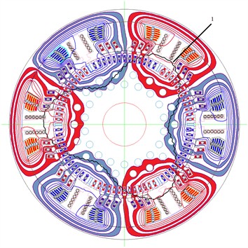
The figure shows a cross-section of an electric machine – that is, the magnetic system of the stator and rotor (iron core, windings and air gap). In this view:
– Red lines indicate the flow of magnetic flux in one direction (for example, from the north pole to the south).
– Blue lines indicate the flow of magnetic flux in the opposite direction.
These colors correspond to the sign of the magnetic induction density (positive or negative).
With the help of such a graph:
– The magnetic saturation zones of the machine are determined.
– The magnetic circuit design (core shape, number of teeth, air gap) is optimized.
– Magnetic losses and torque pulsations are reduced.
Fig. 2Equipotential lines of the vector magnetic potential and the distribution of induction of the ED-118b TED model, where 1 is the distribution of induction along the normal in the lower part of the anchor body
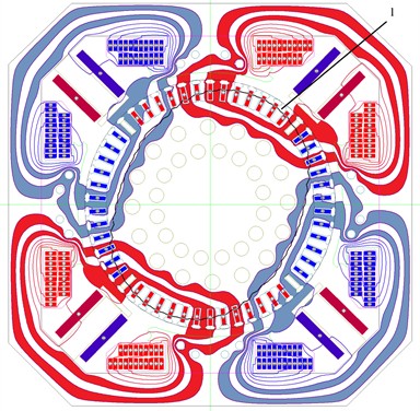
This figure shows a cross-sectional view (2D section) of the ED-118 electric machine, divided into 6 sectors — this is a 6-pole (3 pole pairs) machine.
Each pole pair creates the same magnetic field pattern, so this model is calculated for 1/6 of the sector and then multiplied to the entire machine (with symmetrical conditions).
This image was obtained using the Finite Element Method (FEM):
– Each area (stator, rotor, air gap) is covered with a mesh.
– The vector potential value for each node is solved.
Then the magnetic induction vector field is calculated using and .
The contour lines (red/blue zones) are the isolines of this B-field.
3. Results and discussion
The first medium-speed DC electric rolling stock was selected for the study. It was designed and built at the Riga Carriage Works and the Riga Electric Machine-Building Plant as the ER9E suburban electric rolling stock. It entered service on the Tashkent Railway on the Tashkent-Khodjikent line in the late 1970s. The choice of this type of electric rolling stock for the study was due to the inclusion of self-ventilated permanent electric locomotives of the NB-406 model with series excitation and frame suspension in the train design. Its design is similar to the TEM RT-51D model discussed above. The 25,000 V AC electric train is intended for intercity passenger transportation at a speed of 130 km/h. Scheme of a 12-car combined electric train: G+(M+MT)×6+G, where G is the head car, M is the car, MT is the car with the pantograph; (M+MT) – one traction section[24, 22]. Table 2 presents the main technical parameters of the ER9E medium-class electric train, taken from [19]. The traction motor design consists of an octagonal cast steel frame, a 535 mm diameter anchor, four main poles, and four auxiliary poles; the anchor has 58 slots.
Fig. 3 shows the distribution of equipotential lines of the vector magnetic potential of the ER9E electric train's traction motor [24, 25].
Table 2Main technical characteristics of the ER9E electric train (12 cars)
Key indicators | Electric train ER9E |
Total weight, T | 582 |
Train Length (axle length), mm | 292400 |
Total power, kW | 11000 |
Nominal voltage, V | 27000 |
Nominal voltage, V | 220 |
Average acceleration from 0 to design speed, m/s2 | 0.22 |
Number of motor cars, Units | 12 |
Number of electric motors, Units | 48 |
Train electric motor model | NB-406 |
Fig. 3Equipotential lines of the vector magnetic potential of the TED model NB-406 and the distribution of induction, where 1 is the distribution of induction along the normal at the bottom of the anchor slot
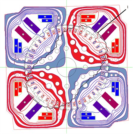
This figure shows a cross-sectional view (2D section) of the NB-406 electric machine, divided into 4 sectors – this is a 4-pole machine.
Each pole pair creates the same magnetic field pattern, so this model is calculated for 1/4 of the sector and then multiplied to the entire machine (with symmetrical conditions).
Using this figure, it is possible to determine the magnetic saturation points.
– It is possible to check the correctness of the location and orientation of the windings.
– The symmetry of the magnetic flux in the air gap is observed, which indicates that the machine design is correctly designed.
– The fact that the magnetic flux lines for each pole pair form a closed contour – indicates that the model is working correctly.
4. Conclusions
As a result of the above analysis, the following conclusions can be drawn:
1) The use of numerical methods for determining the magnetic field parameters of torque electric motors allows us to characterize their design features, which is necessary to complement existing mathematical models, and to determine the efficiency of torque electric motors as energy converters.
2) A numerical calculation of the magnetic field vector potentials of domestic torque electric motors used in rolling stock, including high-speed electric rolling stock, subway cars, electric locomotives, diesel locomotives, and foreign-made ones, was conducted. Design and operational features were examined, and comparative tables were compiled.
3) The results of the research offer modern approaches to the analysis of magnetic field characteristics of traction electric machines. The proposed methods allow to increase the energy efficiency of electric machines, reduce electromagnetic losses and optimize design solutions. The obtained scientific results can be recognized as a theoretical basis for research in the field of electric machines at the international level and as a scientific innovation of practical importance.
References
-
A. P. Burman, Y. K. Rozanov, and Y. G. Shakaryan, Electricity Flow Management and Improving the Efficiency of Electric Power Systems. Moscow: MPEI Publishing House, 2012.
-
“Uztemiryol’mashta’mir” UK plant repair instructions, Jan. 2016.
-
V. P. Bocharov, G. V. Vasilenko, and A. P. Kurochka, Mainline Electric Locomotives. Traction Electric Machines. Moscow: Energoatomizdat, 1992.
-
A. T. Golovaty, I. P. Isaev, A. V. Gorsky, and A. P. Buynosov, “System of locomotive repair on specific sections of circulation,” Railway Transport, No. 7, pp. 40–44, 1992.
-
V. P. Smirnov, Continuous Temperature Control of Extremely Loaded Equipment of an Electric Locomotive. Publishing House, 2003.
-
A. M. Khudonogov, “Analysis of the reliability of the insulation of the windings of electric machines of traction rolling stock taking into account the peculiarities of the climatic conditions of the external environment,” Scientific problems of transport in Siberia and the Far East, No. 2, pp. 232–236, 2009.
-
A. T. Osyaev, Increasing the service life of traction electric motors: collection of reports and communications from a scientific and technical conference. 2004.
-
“Thermal tests of the NB-514 traction motor,” UE “Uztemiryulmashtamir” Protocol No EM-18-15, 2019.
-
“Thermal tests of the NB-418 traction engine,” UE “Uztemiryulmashtamir” Protocol No EM-18-15, 2018.
-
A. S. Serebryakov, “Electrical engineering materials science,” in Electrical Insulating Materials: a Textbook for Higher Educational Institutions of the Railway, Moscow: Route, 2005, p. 280.
-
S. K. Ismailov, “Electrical strength of insulation of electric machines of locomotives,” Omsk state, University of Railways, 2013.
-
V. N. Ivanov, “Reliability of electric machines of traction rolling stock,” Scientific Problems of Transport in Siberia and the Far East, No. 1, pp. 196–198, 2008.
-
D. A. Olentsevich, “Improvement of the system of technical maintenance of insulation of traction motors of electric locomotives,” Irkutsk, 2010.
-
“Analysis of the technical condition of the electric locomotive fleet along the railway network of Uzbekistan for 2009,” Moscow, 2018.
-
A. M. Khudonogov, “Restoration of the insulation properties of the armature windings of the traction electric motor,” Bulletin of ISTU, Vol. 4, No. 28, pp. 60–62, 2006.
-
D. V. Konovalenko, “Rational modes of drying of humidified insulation of windings of traction electric machines,” Irkutsk, 2007.
-
“Instructions for preparation for work and maintenance of electric locomotives in winter and summer conditions,” TsT / 814 from 10.04.2009, 2009.
-
“Order on the system of maintenance and repair of locomotives of JSC "UzRW" No. 3r,” Transport, Moscow, 2014.
-
“Rules for the repair of electric vehicles of electric rolling stock,” Transport, Moscow, TsT-TsTVR / 4782, 1975.
-
A. V. Grishchenko, Electric Machines and Converters of Rolling Stock. Moscow: ACADEMA, 2005.
-
S. Nuriddinov, B. Avazov, F. Hasanov, and Y. Rakhmonova, “Analysis of the causes of traction electric failures of electric cargo cars operated on railways of the Republic of Uzbekistan,” in E3S Web of Conferences, Vol. 264, p. 05041, Jun. 2021, https://doi.org/10.1051/e3sconf/202126405041
-
N. M. Vas’Ko et al., Electric Locomotive VL80S: Operating Manual. (in Russian), Moscow: Transport, 1990.
-
Y. N. Vetrov and M. V. Pristavko, Design of Traction Rolling Stock: Textbook for Students of Technical Schools and Colleges of Railway Transport. Moscow: Zheldorizdat, 2000.
-
S. P. Filonov, A. E. Ziborov, and V. V. Razumeychik, Diesel Locomotive 2M62: Crew Compartment, Electrical and Auxiliary Equipment. Moscow: Transport, 1987.
-
L. V. Gutkin, Y. N. Dymant, and I. A. Ivanov, Electric train ER200. Moscow: Transport, 1981.
About this article

The authors have not disclosed any funding.
The datasets generated during and/or analyzed during the current study are available from the corresponding author on reasonable request.
The authors declare that they have no conflict of interest.
