Abstract
This study examines the effect of elevated operating temperatures on the structural durability of locomotive frame assemblies. Material specimens taken from long-serving locomotive frames were tested under controlled heating up to 100 °C to evaluate thermal-mechanical responses using calibrated strain gauges and temperature sensors at critical load-bearing zones. The statistical analysis of the results (mean values, standard deviations, confidence intervals) confirmed data reliability. Elevated temperatures were found to reduce the yield strength, elastic modulus, and fatigue endurance limit of structural steels, resulting in an estimated 15-17 % decrease in service life compared with normal conditions. The novelty of this research lies in incorporating thermal degradation into the durability model of locomotive structures, providing a more realistic basis for strength assessment and design optimisation of rolling stock operating under high-temperature environments.
1. Introduction
The frame structures of locomotives consist of individual elements and welded joints of various configurations, which are subjected to a wide range of alternating loads [1]. The strength of such structures is determined by a number of factors, including design and technological features, as well as methods of connecting elements to each other [2]. The service life and durability of welded structures in traction rolling stock during operation are influenced by various factors, the main of which are the speed and intensity of operation, characteristics of the construction material, quality of welded joints, temperature conditions, random nature of cyclic alternating loads, frequency of load application and stress amplitude, as well as static and dynamic loads arising in different operating modes [3]-[7], [22]. This article examines the impact of factors such as elevated temperatures during operation on the service life of rolling stock structures.
Locomotive frame structures are primarily manufactured using welding techniques from sheet elements with open or closed cross-sections [8]. Locomotive bogies operated in CIS countries mainly utilize frames consisting of box-shaped beams welded from horizontal and vertical sheets [5], [6], [18]-[21]. The presence of residual stresses in welded joints significantly reduces the resistance to brittle fracture and notably affects the fatigue strength of welded connections. This is observed in the side frames and transverse beams of locomotive bogie frames, particularly in areas where parts of varying rigidity such as brackets, suspensions, and plates are welded to them [5], [6], [12]-[15]. This creates localized plastic deformation in the main elements, causing acute stress concentration [2]. Furthermore, during operation, locomotive frame structures are exposed to elevated temperatures, leading to changes in material properties [9].
2. Impact of elevated operating temperatures on the service life of rolling stock structures
The ambient temperature affects load-bearing structures, as temperature fluctuations also impact the characteristics and properties of structural materials. In this regard, regulatory documents for determining crack resistance (fracture toughness) characteristics under cyclic loading take into account the temperature acting on the material [10].
This effect is caused by strain aging of steel: at low temperatures, impurity atoms have low mobility, which prevents the formation of atmospheres around dislocations and allows them to slide unimpeded [11]. At high temperatures, the diffusion rate of impurity carbon atoms increases, which enhances the mobility of dislocations in steel.
As conditions change from low-temperature fatigue to high-temperature fatigue, the nature of material fatigue failure also changes. Intragranular fracture transitions to intergranular fracture, which initiates at grain boundary junctions or at the sites of pores forming along these boundaries. The appearance of pores is associated with the interaction between well-developed slip bands and grain boundaries.
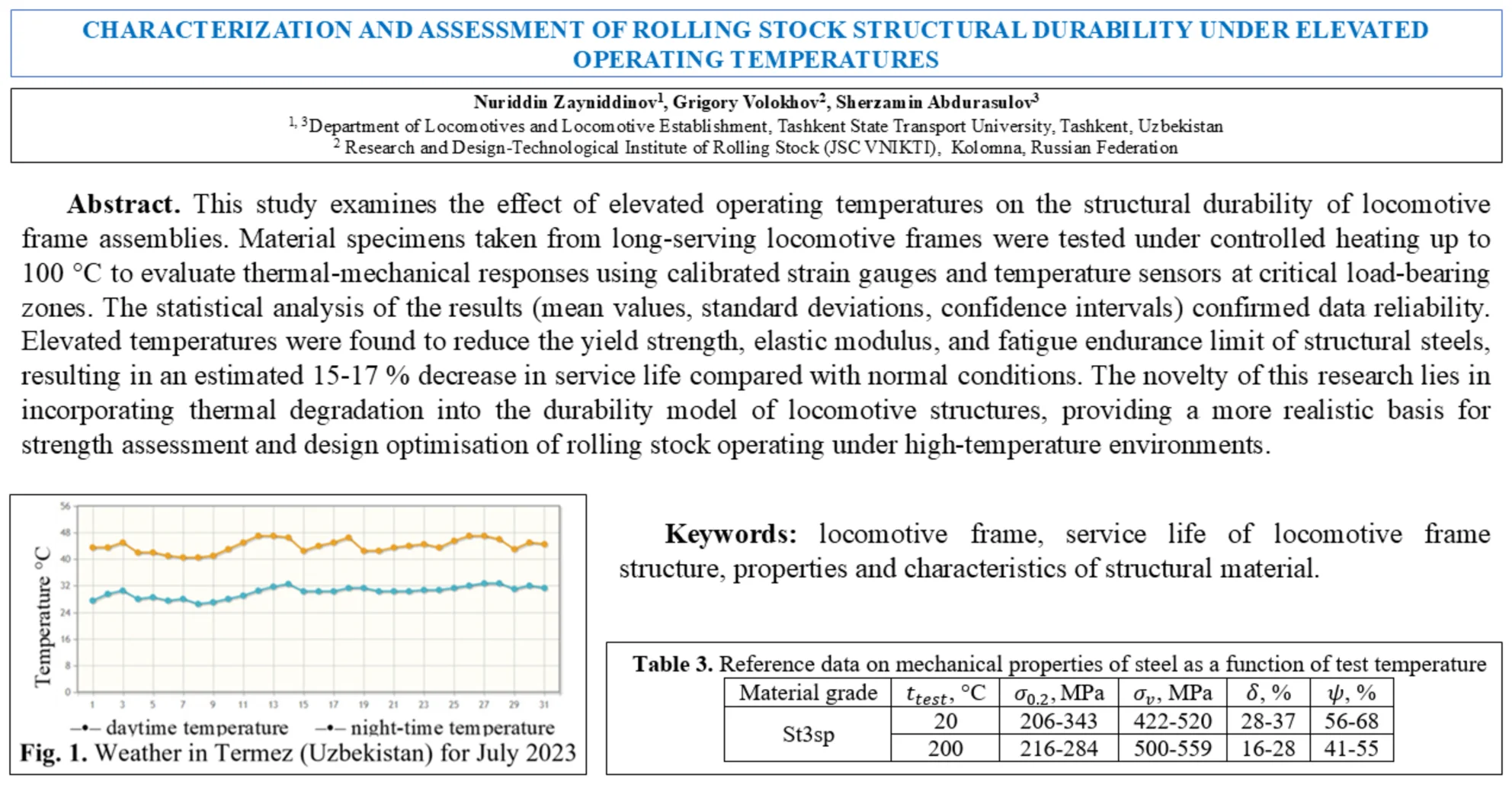
Analysis of the natural and climatic conditions for locomotive operation shows that the Republic of Uzbekistan is characterized by a hot climate. In the summer months from June to August, the air temperature ( °C) can reach about 50 °C and remain at this level for an extended period. According to statistical data, the daytime temperature in the south (Termez) stays around +42 °C, while in the evening it drops to +20 °C. Fig. 1 presents the temperature analysis data for the city of Termez in southern Uzbekistan for the month of July from 2021 to 2023.
Fig. 1Weather in Termez (Uzbekistan) for July 2023
In 2023, the highest daytime temperature in July reached 47 °C, while the lowest night-time temperature dropped to 26 °C. The average daytime and night-time temperatures throughout July were 44.0 °C and 30.1 °C, respectively. When operating rolling stock under these conditions, its supporting structures (undercarriage, body) can heat up to 100 °C or more.
High temperatures affect the properties of materials, causing a decrease in tensile strength, yield strength, and elastic moduli. This can also impact fatigue strength, which represents the material's ability to withstand repeated loads. At high temperatures, fatigue strength may become time-dependent due to various processes, such as diffusion and dislocation restructuring. This can lead to increased plastic deformation, also known as creep, which can intensify the accumulation of fatigue damage and potentially result in other failure mechanisms.
The properties of the material also depend on temperature. Tensile strength, yield strength, and elastic moduli decrease as temperature increases. The endurance limit, also known as fatigue strength, at high temperatures refers to the maximum stress level that a material can withstand for an infinite number of cycles without experiencing fatigue failure.
At high temperatures, the endurance limit of a material typically decreases due to a phenomenon known as creep, which is the gradual deformation of material under constant stress. This can cause microstructural changes and lead to a reduction in the material's fatigue strength. The endurance limit at high temperatures can be determined through fatigue tests, in which the material is subjected to cyclic loading at various stress levels, and the number of cycles until failure is recorded. The data is then analysed to determine the endurance limit at a specific temperature.
The endurance limit of components at high temperatures can be influenced by various factors, such as material composition, microstructure and heat treatment, loading conditions, and others.
When determining the service life at calculated temperatures during the assessment of locomotive component conditions, the basic calculated characteristics of mechanical properties , , , , are determined at room (normal) temperature ( = 20 °C, = 293 K) using destructive methods. For this purpose, data from destructive tests of samples cut from the analyzed structural element are utilized.
To account for the impact of primary operational factors (time, temperature, environment) on the components of traction rolling stock units, which can affect changes in mechanical properties, the calculations additionally incorporate reduced characteristics , , , , , adjusted for operational damage.
To account for mechanical properties at the calculated temperature and the transition from mechanical properties of materials at room temperature, the following relationships are used [9], [11], [16]:
where is a coefficient that depends on the type of steel and is determined experimentally.
For the purpose of calculations, and in the absence of specific experimental data, the coefficient for low-carbon and low-alloy steels can reasonably be taken as 0.004, which corresponds to the typical range reported in material standards and previous studies. For calculations in the absence of experimental data, the value of for low-carbon and low-alloy steels can be taken as 0.004. The value of is defined as the fracture stress in the necked region of the specimen, obtained from static test data or calculated using the formula [2], [9]:
where is the yield strength at the critical brittleness temperature for a smooth sample during stretching, determined experimentally; – characteristic of steel, determined experimentally.
In the absence of direct experimental data, the following parameter values are adopted based on literature and standard engineering practice [2], [9]:
where , and are steel characteristics dependent on strength, which are either established experimentally or determined from the following relationships:
where – yield strength (and proportionality limit) with a plastic strain tolerance of 0.02 % and:
For low-carbon and low-alloy steels, ≥ 40%.
Table 1Steel properties
, MPa | 200 | 250 | 300 | 350 | 400 | 500 |
160 | 140 | 120 | 105 | 90 | 68 |
3. Calculating the service life of locomotive frames
The calculation of frame structure lifespan, considering local elastic-plastic deformations and cyclic changes that may lead to low-cycle quasi-static or fatigue-type failures, can be performed taking into account the potential emergence and accumulation of residual deformations in locomotive structure materials. This type of loading is described by low-cycle fatigue deformation criteria in the form of Manson-Coffin-Langer equations, which characterize the exhaustion of plastic properties at a destructive (Np) number of loading cycles [2], [8], [10], [11], [17]:
where: is the range or unilateral plastic relative deformation in the loading cycle with a given force; is the strengthening diagram indicator beyond the material's elastic limit; is an empirical parameter of the material, representing the relative reduction of area in the specimen's neck (according to GOST 25.502) at rupture; and are the endurance limits of the material and the part, respectively; is the elastic modulus of the material; is the cycle asymmetry coefficient.
The resource estimation based on the universal failure model of type Eq. (13), developed at VNIKTI [1], [10], [17], most accurately reflects the accumulation of damage under stresses causing elastic and elastic-plastic deformations during complex loading of a part. This model provides results that closely match experimental data:
The elements of this equation characterize both the plastic (first term) and elastic components of cyclic deformation.
The coefficient accounts for the reduction in the endurance limit of the component material under the influence of inelastic deformations, while the coefficient at considers the proportion of quasi-static loads in the operational unit block with a number (for example, annual); where is the range of plastic deformation during the loading cycle, and the coefficients and are constants dependent on the material properties; is the load corresponding to the yield strength of the structural material; is the ultimate (destructive) load on a structural element in the elastic-plastic region.
The absence of cracks and noticeable residual deformations at the welding point of the tension box to the spine beam of the 2TE116 locomotive frame after more than 45 years of operation also confirms the structure’s functionality, despite a slight exceedance of the permissible value ([] = = 220.5 MPa) measured during the normal separation tensile test.
Taking into account the temperature affecting the structures and its influence on material characteristics, we will perform calculations considering the operation of structures under elevated ambient temperatures and corresponding metal heating (results in Table 2). In these calculations, we used the values of , , (at ≈ 100 °C) that are reduced compared to the corresponding values under normal conditions (at = 20 °C). The results show a significant decrease in resource indicators, with service life reduced by approximately 15-17 %.
Using the formula based on the data provided above, we determine:
At = 100 °C, we obtain:
We find = 0.10248⸱0.04343 = 0.0445 and = 1.11.
Then = 216 MPa, which aligns well with the reference data (Table 3).
Table 2Results of calculating the durability of the diesel locomotive frame at elevated temperatures
Measurable parameters | Investigated construction | ||
The end section of the diesel locomotive’s main frame, accounting for temperature effects | |||
Designation | Unit of measurement | At 20 °C | At 100 °C |
– | 0.002 | 0.0018 | |
, | – | 0.58 | 0.52 |
– | 0.43 | 0.35 | |
– | 0.4 | 0.4 | |
MPa | 35 | 30 | |
MPa | 2.0×10⁵ | 1.5×10⁵ | |
, ( ) | kN | 2500 | 2000 |
kN | 4500 | 3600 | |
cycle | 10 | 10 | |
cycle | 12×103 | 12×103 | |
– | 0.3 | 0.3 | |
years | 58 | 48 | |
Table 3Reference data on mechanical properties of steel as a function of test temperature
Material grade | , °C | ,MPa | , MPa | , % | , % |
St3sp | 20 | 206-343 | 422-520 | 28-37 | 56-68 |
200 | 216-284 | 500-559 | 16-28 | 41-55 |
4. Conclusions
The analysis confirms that elevated operational temperatures significantly affect the strength and fatigue behaviour of locomotive frame materials. Increasing temperature causes a gradual decrease in yield strength, elastic modulus, and endurance limit, resulting in a reduced fatigue life of welded and bolted joints.
Experimental testing at 100 °C revealed an average 15-17 % reduction in predicted service life compared with standard conditions. Statistical evaluation of the results (mean ± standard deviation, 95 % confidence interval) verified the consistency and reliability of the data, while uncertainty analysis based on the ISO GUM methodology identified strain gauge calibration and thermal gradient measurement as the main sources of uncertainty.
Practically, the findings emphasise the need to include temperature-induced degradation effects in durability assessments of traction rolling stock structures. The proposed approach enables a more realistic estimation of service life under real climatic conditions. The study’s novelty lies in integrating experimental thermal analysis with a durability prediction model, thereby linking thermal exposure, material degradation, and long-term reliability of locomotive frames.
Future research will aim to refine the statistical uncertainty model and validate the predicted fatigue life through full-scale thermal cycling experiments.
References
-
E. S. Oganyan and G. M. Volokhov, “Calculations and strength testing of locomotive load-bearing structures,” (in Russian), FGBOU Educational and Methodological Center for Railway Transport, Moscow, 2013.
-
V. P. Kogaev, N. A. Makhutov, and A. P. Gusenkov, Calculations of Machine Parts and Structures for Strength and Durability. (in Russian), Moscow: Mashinostroyeniye, 1985.
-
S. Abdurasulov, N. Zayniddinov, O. Khamidov, A. Yusufov, and S. Jamilov, “Stress-strain state analysis of cross beam of main frame of industrial electric locomotives PE2M and PE2U,” in The 3rd International Symposium on Civil, Environmental, and Infrastructure Engineering (ISCEIE) 2024, Vol. 3317, No. 1, p. 060011, Jan. 2025, https://doi.org/10.1063/5.0266927
-
A. Grishchenko, A. M. Yusufov, and D. N. Kurilkin, “Forecasting the residual service life of the main frame and extending the service life of shunting locomotives JSC “UTY”,” in E3S Web of Conferences, Vol. 460, p. 06032, Dec. 2023, https://doi.org/10.1051/e3sconf/202346006032
-
S. Abdurasulov, N. Zayniddinov, A. Yusufov, and S. Jamilov, “Analysis of stress-strain state of bogie frame of PE2U and PE2M industrial traction unit,” in E3S Web of Conferences, Vol. 401, p. 04022, Jul. 2023, https://doi.org/10.1051/e3sconf/202340104022
-
A. Yusufov, O. Khamidov, N. Zayniddinov, and S. Abdurasulov, “Prediction of the stress – strain state of the bogie frames of shunting locomotives using the finite element method,” in E3S Web of Conferences, Vol. 401, p. 03041, Jul. 2023, https://doi.org/10.1051/e3sconf/202340103041
-
O. Khamidov, A. Yusufov, S. Jamilov, and S. Kudratov, “Remaining life of main frame and extension of service life of shunting locomotives on railways of Republic of Uzbekistan,” in E3S Web of Conferences, Vol. 365, p. 05008, Jan. 2023, https://doi.org/10.1051/e3sconf/202336505008
-
“Standards for calculating and evaluating the strength of load-bearing elements, dynamic qualities, and track impact of the running gear of 1520 mm gauge railway locomotives,” (in Russian), Ministry of Railways, Moscow, 1998.
-
N. A. Makhutov, Structural Strength, Service Life, and Technogenic Safety. (in Russian), Novosibirsk: Nauka, 2005.
-
E. S. Oganyan, “Criteria for the load-bearing capacity of locomotive structures under extreme loading conditions,” (in Russian), MIIT, Moscow, 2004.
-
N. A. Makhutov, Deformation Criteria for Fracture and Strength Calculation of Structural Elements. (in Russian), Moscow: Mashinostroyeniye, 1981.
-
M. Ozsoy, K. Pehlivan, M. Firat, N. Ozsoy, and V. Ucar, “Structural strength and fatigue life calculation of Y32 bogie frame by finite element method,” Acta Physica Polonica A, Vol. 128, No. 2B, pp. B–327-B-329, Aug. 2015, https://doi.org/10.12693/aphyspola.128.b-327
-
E. S. Oganyan, G. M. Volokhov, A. S. Gasyuk, and D. M. Fazliakhmetov, “Calculated experimental evaluation of the operating life of basic locomotive parts for ensuring their safe operation,” Journal of Machinery Manufacture and Reliability, Vol. 47, No. 2, pp. 155–159, Apr. 2018, https://doi.org/10.3103/s1052618818020097
-
E. S. Oganyan, G. M. Volohov, and A. S. Gasyuk, “Justification of safe operation of rolling stock by the lifetime of its bearing structures,” in IOP Conference Series: Materials Science and Engineering, Vol. 1079, No. 5, p. 052089, Mar. 2021, https://doi.org/10.1088/1757-899x/1079/5/052089
-
J.-W. Seo, H.-M. Hur, S.-J. Kwon, and K.-H. Moon, “Effect of multiple weld repairs on fatigue strength of bogie frame of railroad vehicle,” Advances in Mechanical Engineering, Vol. 15, No. 11, p. 16878, Nov. 2023, https://doi.org/10.1177/16878132231213596
-
N. Makhutov and M. Gadenin, “Behavior of low-cycle damages accumulation taking into account loading service parameters,” (in Russian), University Aerospace Engineering Bulletin, No. 56, pp. 45–57, Jan. 2019, https://doi.org/10.15593/2224-9982/2019.56.04
-
E. S. Oganyan, “Deformation criterion of damage accumulation under high – and low-cycle loading (in Russian),” (in Russian), Heavy Mechanical Engineering, No. 7, pp. 12–14, 2006.
-
Z. Mukhamedova et al., “Calculating the fatigue strength of load-bearing structures of special self-propelled rolling stock,” Scientific Reports, Vol. 14, No. 1, p. 19205, Aug. 2024, https://doi.org/10.1038/s41598-024-70169-0
-
O. Fomin, J. Gerlici, A. Lovska, and K. Kravchenko, “Research into the loading of the tank car frame concept with filler in the composite center sill,” Communications – Scientific letters of the University of Zilina, Vol. 24, No. 3, pp. B219–B227, Jul. 2022, https://doi.org/10.26552/com.c.2022.3.b219-b227
-
O. Koshel, S. Sapronova, and S. Kara, “Revealing patterns in the stressed-strained state of load-bearing structures in special rolling stock to further improve them,” Eastern-European Journal of Enterprise Technologies, Vol. 4, No. 7 (124), pp. 30–42, Aug. 2023, https://doi.org/10.15587/1729-4061.2023.285894
-
D. Bannikov, A. Radkevich, and A. Muntian, “Modernization of the buffer beam of PE2U traction unit electric locomotive,” in IOP Conference Series: Materials Science and Engineering, Vol. 985, No. 1, p. 012035, Nov. 2020, https://doi.org/10.1088/1757-899x/985/1/012035
-
C. Miao, H. Wang, and Y. Song, “The correlation between static strength and fatigue strength test and simulation,” in Journal of Physics: Conference Series, Vol. 2660, No. 1, p. 012042, Dec. 2023, https://doi.org/10.1088/1742-6596/2660/1/012042
About this article

The authors have not disclosed any funding.
The datasets generated during and/or analyzed during the current study are available from the corresponding author on reasonable request.
The authors declare that they have no conflict of interest.
