Abstract
The object of this study is the interaction of the wheel-lubricant-rail system. The subject of the study is elastic deformations in the contact zone of the wheel-lubricant-rail system depending on the properties of the lubricant. This paper proposes a model for assessing the influence of lubricant on wheel-rail interaction. The proposed method, with varying input data, can be used to determine the optimal lubricant for a specific region.
Highlights
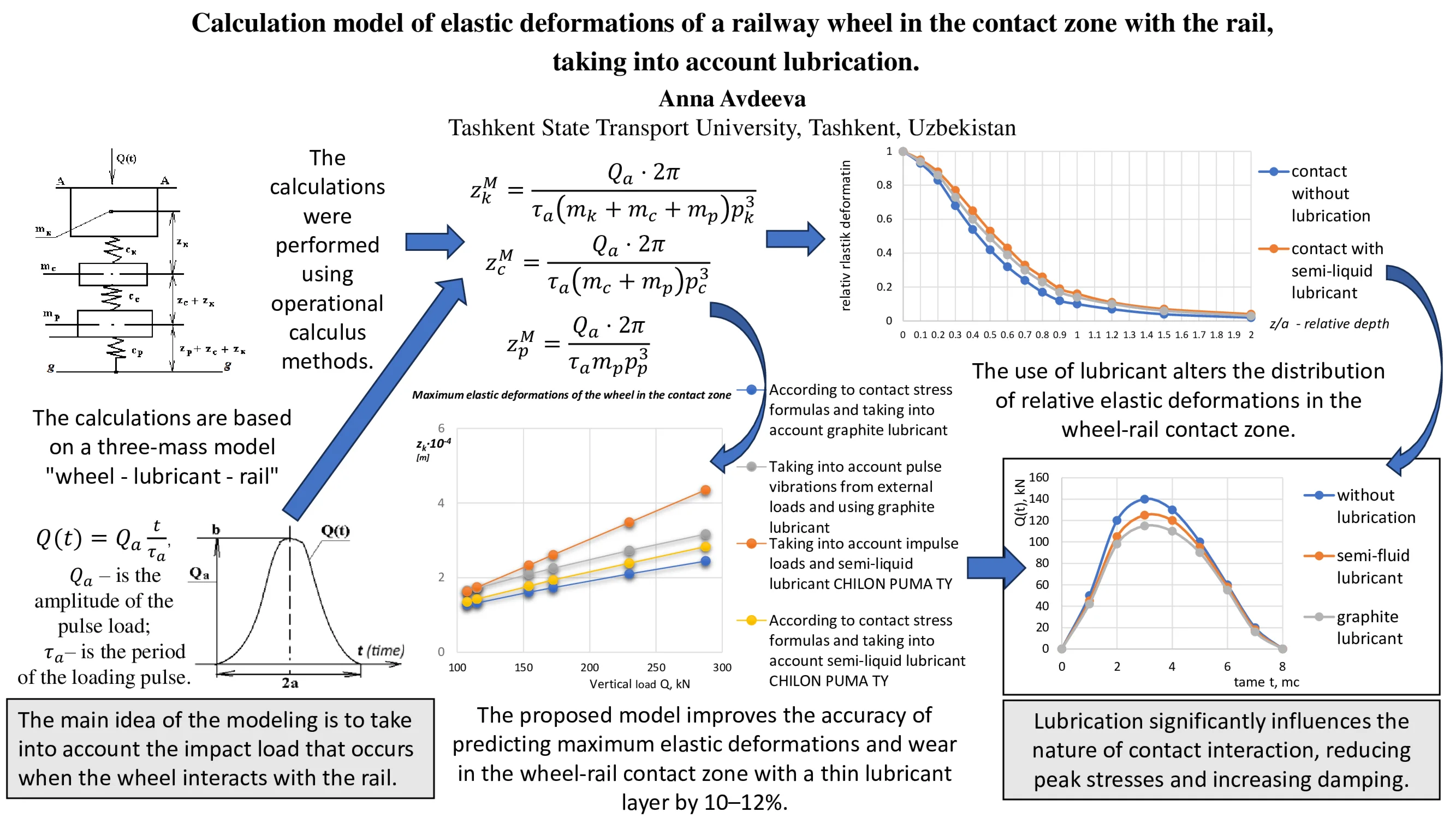
- The calculations are based on a three-mass "wheel-lubricant-rail" model. The key concept behind the modeling is to account for the impact load arising from wheel-rail interaction. The calculations were conducted using operational calculus methods.
- The verification and validation procedures allow us to consider the proposed calculation model reliable within the accepted assumptions.
- Lubricant significantly influences the nature of the contact interaction, reducing peak stresses and increasing damping.
- Oil lubricants are effective under moderate-intensity dynamic loads, while solid lubricants are effective under repeated impacts and high pressures.
- The calculation model improves the accuracy of fatigue wear predictions by 10–12%. The resulting relationships can be used to adjust standard methods for assessing the durability of wheelsets and rails.
1. Introduction
The efficiency and safety of rail transport depend primarily on the interaction between rolling stock and rails. Many Uzbekistan Railways tracks contain curved sections of track, which result in increased wear on locomotive wheel flanges and lateral wear on rail heads, leading to significant material losses. Wear reduces the energy efficiency of railways by 30-35 %. It is impossible to completely eliminate wear in the wheel-rail system, as both rolling and sliding friction occur when the wheel rolls along the rail. Currently, to reduce wear and increase the service life of the tire and rail, both worldwide and at Uzbekistan Railways, lubrication is being carried out. However, choosing the wrong lubricant can have the opposite effect: increased wear on rails and wheels, as well as noise on curved sections of track. Incorrect or excessive lubrication of rails and wheels also leads to negative consequences: reduced wheel-rail adhesion, which can lead to slippage, the formation of rail defects (such as buckling), and increased wheel and rail wear. Therefore, when selecting a lubricator, it is crucial to have an objective model of the interaction between the lubricant, the wheel, and the rail.
Numerous studies conducted by scientists around the world are devoted to the problem under consideration [1-7]. The work [1] presents an analysis of the operation of rolling stock and a calculation of the savings in fuel and energy resources when using lubrication. Works [2, 3] focus on increasing the efficiency of locomotive wheel flange lubrication by using a specialized lubricating device. However, the models presented in these works consider the interaction of the wheel exclusively with the lubricating disk, without offering a general model of the “wheel – lubricant – rail” system. The study [4] analyzes combined lubrication, including lubrication of the side surface of the outer rail and the running surface of the inner rail. Work [5] is devoted to improving the technology of lubricant application. The authors of all the mentioned works emphasize the feasibility of using lubrication to reduce wheel and rail wear. These conclusions are based on experimental and statistical data, while a clear and realistic mathematical model describing the process is absent. The work [6] presents a mathematical model of the dependence of contact stresses on the wear of wheelsets of railway rolling stock, but without taking into account the influence of lubrication. An alternative approach to combating wear is to change the design parameters [7], but this measure appears to be quite costly.
The aim of the study is to create a calculation model of the interaction between a wheel and a rail under impact loading, taking into account the lubricant layer.
2. Methods
Rail fatigue failure and crack formation, increased noise and vibration in rail fastening assemblies and bogie suspension systems, provide practical grounds for assuming that wheel-rail interaction is impulsive in nature, meaning the load is transmitted in the form of short dynamic shocks. Physical causes of impulsive wheel-rail interaction include track irregularities and joints, wheel ovality or localized defects, and uneven track rigidity at joints, turnouts, and bridge crossings. There is also experimental evidence [8-10] of impact loading in the wheel-rail contact zone. A mathematical model of the interaction between a wheel and a rail under impact loading, taking into account the lubricant layer, includes three masses (Fig. 1).
The first component of the system accounts for the unsprung mass of the wheelset, distributed over a single wheel:
where is the unsprung weight per wheel; is the acceleration due to gravity.
The second is the mass of the lubricant:
where is the thickness of the initial lubricant layer; is the lubricant density; is the acceleration due to gravity; , are the dimensions of the semi-axes of the contact area ellipse , determined using the formulas of contact stress theory [11].
The third is the mass of the track section between the sleeper axes:
where is the mass of one linear meter of rail; – distance between sleepers.
Fig. 1Model of interaction of the wheel-lubricant-rail system: a) three-mass model; b) diagram of the pulse load function Qt acting in the contact zone of the wheel and rail
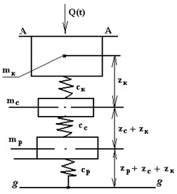
а)
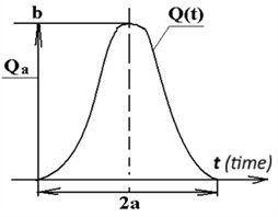
b)
According to Hooke's law, we take into account the reduced stiffness due to deformations of the compressed local volume within the wheel material:
where is the first-order elastic modulus of the wheel material; is the depth of the layer in the tire, which determines the elastic compressive deformation waves due to interaction with the rail; is the contact point between the tire and the rail.
Similarly, for lubrication due to volume compression , the stiffness is found using the formula:
where – the equivalent modulus of elasticity of the lubricant in the wheel-rail contact zone; – the wheel-rail contact area; – the depth of the wheel layer achieved by elastic deformation waves during interaction with the rail.
The reduced compressive stiffness of the local volume within the rail material is found using the formula:
where – first-order modulus of elasticity of the wheel material; – wheel-rail contact area; – rail layer depth achieved by elastic deformation waves upon interaction with the wheel.
We introduce the elastic deformation coordinates (Fig. 1(a)): of the mass ; of the mass relative to the mass ; of the mass relative to the mass .
The calculation model includes:
– Kinetic energy:
– Potential energy of elastic deformations:
Work of external force:
Lagrange equations of the 2nd kind for each of the adopted coordinates:
In Eqs. (10-12), we carry out transformations so that the coefficient at is equal to one:
where , , , , , , , .
The solution to the system of Eqs. (13-15) consists of two components: natural oscillations, when the right side of the system is equal to zero (0), and particular solutions that take into account the function of the applied load . The contact force depends on time and has a pulsed nature – a sharp increase followed by attenuation, as shown in Fig. 1(b). The pulse can be described by various functions. Let us assume that the contact force has the form:
where is the amplitude of the pulse load; is the period of the loading pulse; under zero initial conditions: . Using the operational calculus method [12], we obtain the values of maximum elastic deformations in the interaction zone of the wheel and rail, separated by a thin layer of lubricant:
To verify the accuracy of the wheel-rail interaction model, the numerical solution was verified. This was accomplished by comparing the obtained elastic deformation values in the contact zone with an analytical solution based on Hertzian theory [13].
The model was validated by comparing the calculation results with experimental and statistical data obtained at the Uzbekistan locomotive depot of the Uzbekistan Railways. The objective of the field studies was to measure the vertical and lateral elastic deformations of the rail and wheel under various interaction conditions: dry contact, flange lubrication (semi-liquid), and lubricant with solid fillers (graphite). Each contact type was tested at three speeds: 40, 80, and 120 km/h, and three load levels: 60, 90, and 110 kN. A KF5R4-10-200 strain gauge with a constantan foil sensing element was used to obtain readings. The sensors were affixed to the inner and outer surfaces of the wheel rim [14].
Let's carry out calculations for wheelset tires of the Uzbekistan locomotive on the Tashkent-Khavast section. The vertical load is taken based on actual values from 107.5 to 287.5 kN. The radius of rail curvature 300 mm. For the locomotive tire, the radius of curvature of the wheel 525 mm. Unsprung mass of the wheel 1300 kg. The number of sleepers per 1 km of P65 rails is 1840 pcs., 65∙0.5 = 325 N. Mass 32.6 kg per contact patch length. Elastic modulus 2.1×10¹¹ N/m2. To lubricate the rails, we will use two compounds: with a solid graphite filler and a semi-liquid lubricant CHILON PUMATY.
3. Results
To verify the numerical implementation, a calculation was performed using the Hertz method. Calculation parameters: contact patch semiaxis radius 7 mm; maximum pressure: dry contact 1150 MPa; oil lubricant 900 MPa; solid lubricant 980 MPa; reduced modulus of elasticity 1.15×10⁵ MPa. The calculated contact patch radius and maximum pressure differed from the theoretical values by no more than 4.5 %, which confirms the correctness of the elastic contact description and the applied boundary conditions.
When validating the model using experimental data, the following wheel deformation values were obtained (based on tensor sensors): without lubrication – 2.5-3 µm; with lubrication – 2.7-3.3 µm; and under impact – 4.2-5.5 µm (under a vertical load of 90 kN). These results are fully consistent with the calculated values (Fig. 2). Thus, the model adequately describes the physical processes of wheel-rail interaction under impact loading and can be used for subsequent analysis of the effect of lubrication on contact stresses and elastic deformations.
The results of elastic deformation calculations in the wheel-lubricant-rail contact system, obtained using a mathematical model for the actual Tashkent-Khavast test site, are presented in Fig. 2. The diagrams in Fig. 2 show that the use of semi-fluid lubricants and lubricants with solid fillers increases elastic deformations by 5-10 % compared to contact without lubricant. Despite a slight increase in elastic deformations, the level of contact stresses decreases by 15-25 %, which reduces rail and wheel wear.
Fig. 2Diagrams of maximum elastic deformations in the contact zone of the wheel and rail separated by a thin layer of lubricant, found in two ways: taking into account the pulsed external loading, and using the formulas for contact stresses
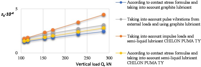
Fig. 3Distribution of relative elastic deformations in the wheel-rail contact zone under different lubrication conditions
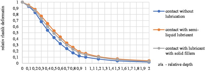
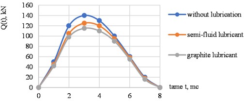
Fig. 4Load diagrams Qt arising in the contact zone of the wheel and rail under different lubrication conditions
To confirm these findings, we evaluate the distribution of relative elastic deformations under the center of wheel-rail contact (Fig. 3). As can be seen from Fig. 3, when using lubricant, an increase in elastic deformations near the surface (by 5-10 %) is observed, which is associated with a decrease in contact pressure and an increase in the contact patch. However, with increasing depth, the differences between the curves decrease, and starting from ( 1.5), the profiles become uniform. Thus, the lubricant primarily affects the surface zone (0-1 mm), reducing stress concentration and the risk of plastic deformation.
Fig. 4 shows the load graphs arising in the wheel-rail contact zone under various lubrication conditions. This is a numerical simulation of the hypothesis regarding the occurrence of a dynamic load in the wheel-rail contact zone. The load acts for a very short period of time, but its magnitude can be very large.
4. Conclusions
A computational model for wheel-rail interaction under impact loading was developed and studied, taking into account the presence of a lubricant layer. Key findings:
1) The verification and validation procedures carried out allow us to consider the proposed calculation model reliable within the accepted assumptions.
2) Lubrication significantly influences the nature of contact interaction, reducing peak stresses and increasing damping.
3) Oil lubrication is effective under moderate-intensity dynamic loads, while solid lubrication is effective under repeated impacts and high pressures.
4) The resulting relationships can be used to adjust standard methods for assessing the durability of wheelsets and rails.
5) Incorporating lubrication parameters into computational models improves the accuracy of fatigue wear prediction by 10-12 %.
References
-
G. V. Chigray and N. V. Kirik, “Lubrication as an aspect of reducing the energy intensity of transportation,” (in Russian), Transport Systems and Transportation Technologies, Vol. 14, 2017.
-
H. Chen, S. Fukagai, Y. Sone, T. Ban, and A. Namura, “Assessment of lubricant applied to wheel/rail interface in curves,” Wear, Vol. 314, No. 1-2, pp. 228–235, Jun. 2014, https://doi.org/10.1016/j.wear.2013.12.006
-
O. Ignatiev and V. Khovorunov, “Modern lubrication systems for wheel-rail tribopairs,” (in Russian), Advances of Modern Science, Vol. 6, No. 3, pp. 148–152, 2017.
-
V. S. Kossov and Y. A. Panin, “Reduction of friction resistance in curves,” (in Russian), Science and Progress of Transport: Bulletin of Dnipropetrovsk National University of Railway Transport, Vol. 5, 2004.
-
D. V. Glazunov, “Methods to reduce wear of rolling stock wheelsets’,” (in Russian), News of the Ural State Mining University, Vol. 2, No. 54, pp. 107–114, Jun. 2019.
-
A. Avdeeva, S. Fayzibaev, and O. Ablyalimov, “Contact stresses and wear of wheel pairs of railways rolling stock,” in The 3rd International Symposium on Civil, Environmental, and Infrastructure Engineering (ISCEIE) 2024, Vol. 3317, p. 060034, Jan. 2025, https://doi.org/10.1063/5.0266926
-
T. Vernaillen, L. Wang, A. Núñez, R. Dollevoet, and Z. Li, “Rail wear rate on the Belgian railway network – a big-data analysis,” International Journal of Rail Transportation, Vol. 12, No. 5, pp. 765–780, Sep. 2024, https://doi.org/10.1080/23248378.2023.2259392
-
A. M. Kulikov, “Contact stresses and wear in the wheel-rail system under impulsive loads,” (in Russian), Science and Transport, No. 4, pp. 22–29, 2019.
-
V. N. Chub and I. A. Kononov, “Calculation features of impulse loads in wheel-rail interaction,” (in Russian), Transport Bulletin, No. 6, pp. 35–42, 2020.
-
D. V. Chyorny and E. G. Pisarev, “Impact load analysis in the wheel-rail system based on vibration diagnostics,” (in Russian), Proceedings of the St. Petersburg University of Railway Transport, No. 3, pp. 49–58, 2022.
-
V. G. Atapin, “Strength of materials,” (in Russian) in Treatise on Architecture, Moscow: Cambridge University Press, 2013, pp. 272–306, https://doi.org/10.1017/cbo9781139839419.012
-
T. L. Anisova and P. G. Lakhmanov, Operational Calculus. (in Russian), Moscow: Urait Publishing, 2025.
-
K. L. Johnson, Contact Mechanics. Cambridge: Cambridge University Press, 1985.
-
“Test methods for railway wheels and rails,” (in Russian), USSR State Standard GOST 24546-80, 1980.
About this article

The authors have not disclosed any funding.
The datasets generated during and/or analyzed during the current study are available from the corresponding author on reasonable request.
The authors declare that they have no conflict of interest.
