Abstract
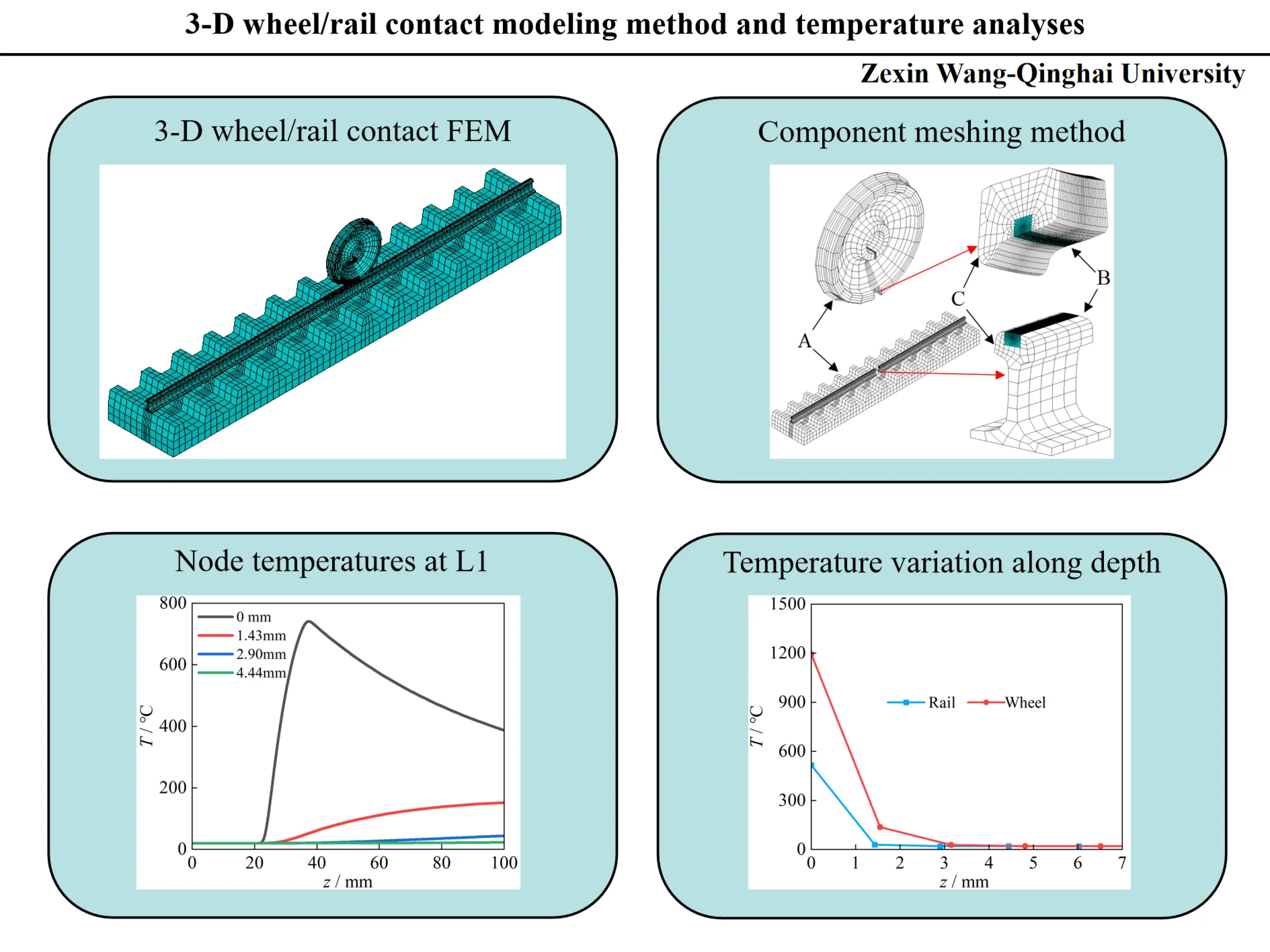
According to the wheel/rail actual dimensions, the modeling process of a 3-D full-size wheel/rail sliding contact finite element model is introduced in detail. During modeling process, the partitioning strategy method and MPC method are adopted. The temperature characteristics of the contact region during sliding contact are researched. The research results show the contact patch shape is close to an ellipse. The stress in the contact area is very concentrated, and the maximum von Mises stress appears in the subsurface at a distance of 2 mm from the contact interface. During the sliding contact, the maximum temperature appears at the contact center. The temperature on wheel contact surface ascends continuously and is significantly greater than the rail surface temperature. High temperatures of contact region are mainly distributed in the contact surface and subsurface, and the influence depth of temperature does not exceed 3 mm.
Highlights
- The modeling process of a 3-D full-size wheel/rail sliding contact finite element model is introduced in detail.
- The partitioning strategy method and MPC method are used to establish the wheel/rail contact model.
- The basic characteristics of wheel/rail contact are obtained.
- The temperature characteristics of the contact region during wheel/rail sliding contact are analyzed.
1. Introduction
As an important product of the Industrial Revolution, railways have played an extremely important role in promoting social development, freight transportation, and information exchange. From the first railway built in Britain in 1825 to the developed railway transportation systems in various countries around the world, railway construction has achieved rapid development. The speed and axle load of the train have significantly increased. During the 18th century, the axle load of trains is only about 10 tons, while currently the United States and Australia operate heavy-duty railways with axle loads of 30 to 40 tons. The train speed has gradually increased from less than 60 km/h to 120 km/h, and now the passenger train speed can reach 350 km/h [1].
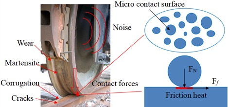
There are enormous vertical forces, lateral force and longitudinal force acting on the interface, the wheel/rail material is prone to damage under these forces (Fig. 1). During the train traction or braking process, the wheel will be in rolling-sliding contact state or pure sliding contact state. At this time, severe friction between wheel and rail can cause surface scratches and can cause phase transformation of the wheel/rail material [2-4]. Thermal load and mechanical load can lead to thermal fatigue cracks and damage to the material. The frictional heat on the surface directly affects the braking performance, driving safety and maintenance cost of the train [5-7].
Fig. 1Damage to wheel tread
Numerical calculation methods are often adopted to research frictional heat. The temperature characteristics, elastic-plastic deformation, stress and thermo-mechanical coupling on contact surface under different contact cases are studied [8-11]. Zhou et al. built a finite element model (FEM) and studied the surface temperature distribution during train breaking [12-15]. Naeimi et al. employed the wheel/rail contact FEM to analyze the thermal fatigue, elastic-plastic deformation, temperature field and stress during the sliding contact process [16-20]. In addition, boundary element method [21], infinite element method [22], Fourier transform [23-25] and Green’s Function [26-28] are employed to research the wheel/rail contact characteristics.
According to the research achievements of authors and other scholars, the method for modeling a three-dimensional (3-D) full-size wheel/rail thermo-mechanical directly coupled FEM is introduced minutely in this paper. The temperature distribution characteristics of the contact region in the braking process are analyzed. The research results in this paper will be helpful to the application of numerical calculation method in thermo-mechanical coupling analysis, and to clarify the temperature distribution law of the contact area.
2. Finite element model
2.1. 3-D wheel/rail contact FEM
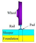
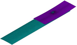
In this paper, a FEM including wheel/rail, pad, sleeper and foundation is established, as shown in Fig. 2. The wheel tread is LM-type tread, and its web type is a S-type plate. The rail is 60 kg/m rail. The cross section is shown in Fig. 3. The wheel diameter is 915 mm, and the rail length is 6.75 m. The sleeper gauge is 0.6 m. The rail can’t is 1:40. The model has 65850 elements and 66020 nodes. The smallest element size is 0.1 mm.
Fig. 2Wheel/rail contact model
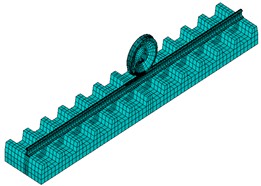
a) FEM
b) Wheel/rail contact
c) Contact pair
Fig. 3Cross section
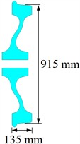
a) Wheel
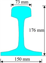
b) Rail
2.2. Meshing method
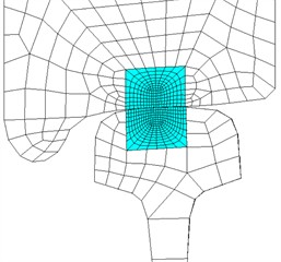
The contact region in models is very small and characterized by significant variations in stress and temperature. In order to obtain accurate stress and temperature values and their distribution patterns, small and high-quality elements are employed in the contact region. However, the contact region only accounts for a small part of the entire wheel/rail component. If small elements are used for overall components, the number of elements and nodes is too large, which can consume computational resources. Therefore, in order to guarantee calculation accuracy and efficiency, the partitioning strategy method is adopted to get the wheel/rail contact FEM.
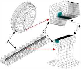
As shown in Fig. 4, the wheel and rail are divided into three parts (part A, part B and part C). In the sliding process, the values of stress and temperature far from the contact region are small and almost constant, and this part is meshed by large size elements (part A). In the sliding contact region, the stress and temperature values are large, and the changes are drastic, the small size elements are used (part B, blue part). The transition part between large-sized elements and small-sized elements is the part C. On the wheel, the nodes between part B and part C are common nodes, and the elements remain continuous. The size of elements in part A and part C is different, and they are connected using the multi-point constraint method (MPC method). On the rail, the two ends of contact region are coarse elements (part A), and the middle is part B and part C. The elements of different sizes between part A and part B/C, and between part B and part C are connected by MPC method. The pad, sleeper and foundation are meshed by coarse elements.
In the FEM, SOLID226 element is adopted to mesh the wheel/rail contact region (part B). SOLID226 element is a hexahedron element and has twenty nodes with up to five degrees of freedom per node. SOLID226 element can be used to analyze multi-field coupling problems. The wheel/rail parts away from contact region (part A and part C), pad, sleeper and foundation are simulated with SOLID185 element. The interaction relationship between wheel and rail is simulated with CONTA174 and TARGE170 elements. This contact pair can emulate the pure rolling contact, rolling-sliding contact and pure sliding contact.
Fig. 4Component meshing method
a) Whole
b) Contact parts
2.3. Calculation parameters and boundary conditions
The material parameters adopted in the FEM are presented in Table 1 [29]. The constitutive relationship of wheel/rail materials is a bilinear hardening model, and the hardening modulus is one in ten of the elastic modulus. The material of the rail pad and sleeper is seen as linear elastic material. The elastic modulus and Poisson’s ratio of the pad are 40 MPa and 0.47, respectively [30]. The modulus of elasticity and Poisson’s ratio of the sleeper are 39.8 GPa and 0.2, respectively. The foundation stiffness is 1200 MPa/m [31]. The convective heat transfer coefficient is 25 W/(m2·℃), and the initial temperature and environment temperature are both 20 ℃.
In the model, the symmetrical constraints are applied on the inner surfaces of the foundation and sleeper. The vertical displacement of the foundation bottom is restricted. The lateral and longitudinal displacements at both ends of rail are constrained. The lateral displacement of wheel is also limited to prevent from falling off the rail surface. The sliding distance of wheel is 100 mm, and the sliding speed is 1 m/s. The load acting on the interface is 100 kN, and applied to the center of wheel.
Table 1Material parameters
Temperature / ℃ | Specific heat capacity / (J/kg·℃) | Thermal conductivity coefficient / (W/m·℃) | Thermal expansion coefficient / (×10-6/℃) | Friction coefficient | Elastic modulus / GPa | Poisson’s ratio | Yield stress / MPa |
25 | 490.1 | 47.7 | 11.0 | 0.334 | 209 | 0.3 | 608 |
100 | 499.9 | 48.9 | 11.6 | 0.301 | 207 | 0.3 | 608 |
650 | 571.5 | 57.8 | 14.8 | 0.139 | 105 | 0.36 | 502 |
1000 | 617.1 | 63.4 | 15.7 | 0.085 | 50 | 0.39 | 237.9 |
1450 | 671.8 | 76.4 | 16.1 | 0.045 | 2.1 | 0.4 | 7 |
3. Results
3.1. Contact characteristics
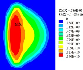
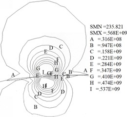
Fig. 5(a) shows the contact stress on the interface. Fig. 5(b) presents the von Mises stress at the contact center. Fig. 5(a) illustrates the wheel/rail contact patch is approximately elliptical, and its area of 121 mm2. Fig. 5(b) indicates the von Mises stress in the contact region is relatively concentrated and gradually decreases outward. The calculation results show the maximum von Mises stress is located at the subsurface of the contact region, with maximum values of 568 MPa. The variation law of von Mises stress during sliding contact has been studied in reference [32], so it will not be studied in this article.
Fig. 5Stress (Pa)
a) Contact stress
b) Von Mises stress
3.2. Temperature fields
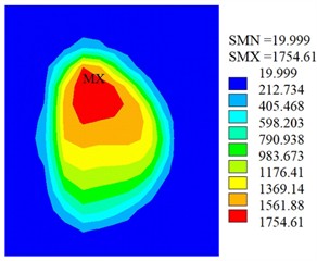
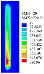
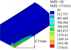
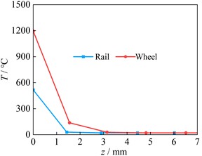
At the end time of sliding contact, the contact surface temperature fields and the sectional drawings of temperature distribution in the contact region are show as Fig. 6 and Fig. 7 respectively. Fig. 6 displays the highest temperature on the surface is located at the contact center, and the maximum temperature of wheel and rail is respectively 1754 ℃ and 721 ℃. Because the wheel contact surface remains unchanged during the sliding contact process, the wheel contact surface temperature is much greater than the values on rail surface. Since the phase transition of the material is not considered in the model, the wheel surface temperature can exceed the melting temperature. Fig. 7 indicates the high temperature is mainly concentrated in the contact region and decreases outward. Due to heat dissipation, the temperature in other regions is low, and the depth of temperature influence does not exceed 3 mm during a single sliding contact process.
3.3. Node temperature
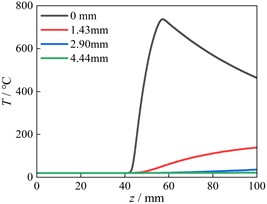
In order to analyze the temperature variation process, several nodes are selected at different depths from contact surface. The node position on the wheel locates at LW position (maximum temperature position), as shown in Fig. 8(a). Three positions (L1, L2, L3) on the rail are selected (Fig. 8(b)). The relationship curves between the temperatures of nodes at different depths from the wheel surface and sliding distance are shown as Fig. 8(c). The temperature rise curves of nodes at the location of L1, L2 and L3 positions on the rail are presented as Fig. 8(d), 8(e) and 8(f), respectively.
Fig. 6Temperature fields (℃)
a) Wheel
b) Rail
Fig. 7Sectional drawings of temperature distribution (℃)
a) Wheel
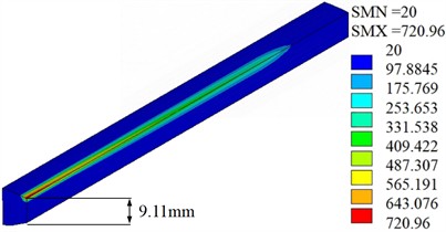
b) Rail
Fig. 8Node temperatures
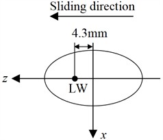
a) Node position on the wheel
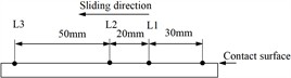
b) Position on the rail
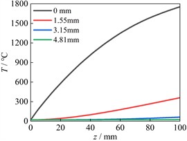
c) Node temperatures at LW
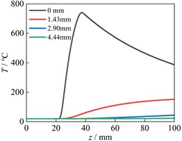
d) Node temperatures at L1
e) Node temperatures at L2
f) Node temperatures at L3
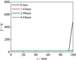
Fig. 8(c) indicates the temperature of node on the wheel surface ascends rapidly with the increase of sliding distance, while the temperature of node at a distance of 1.55 mm from the surface ascends slowly. When the depth to the wheel surface exceeds 3.15 mm, the temperature of nodes remains almost unchanged. In addition, because the wheel contact surface remains unchanged, the temperature on the wheel surface has been continuously increasing. Fig. 8(d) indicates the temperature curve of the surface node at the L1 position has three distinct change stages, which correspond to the wheel approaches the node, passes through the node and moves away from the node. Due to the position of L1 and L2 are located in the middle sliding contact area, the temperature change of nodes at L2 in Fig. 8(e) is the same as that in Fig. 8(d). The node temperatures at L3 have only two stages, without descending stage (Fig. 8(f)). This is because the nodes at L3 are located at the end of sliding contact area, and the wheel only approaches the node and contacts with the node. Therefore, the temperature remains unchanged first and then increases rapidly. Fig. 8 shows the influence region of frictional heat is mainly concentrated on the subsurface and surface. And in a single sliding contact process, the influence of frictional heat is very small when the distance to the contact surface exceeds 3 mm. Fig. 9 shows the temperature variation of surface node at positions of LW and L2 along the depth when the sliding distance is 50 mm. Fig. 9 indicates the temperatures rapidly decrease from the contact surface to the inside. When the depth exceeds 3 mm, the temperature remains unchanged.
Fig. 9Temperature variation along depth
4. Conclusions
In this paper, the modeling method of a 3-D full-size wheel/rail sliding contact FEM is introduced in detail, and the temperature fields and the node temperature change rules during the train sliding process are researched. The main conclusions are obtained.
1) During the process of modelling, the partitioning strategy method and MPC method are employed, and the suitable elements are selected for different contact regions and components. These methods can significantly reduce the number of elements and nodes, while ensuring calculation accuracy and efficiency.
2) The area of contact patch is 121 mm2, and its shape is close to an ellipse. The stress concentration in contact region is relatively obvious, and the maximum von Mises stress in contact region appears on the subsurface at a distance of 2 mm from the contact interface, with maximum values of 568 MPa.
3) During sliding contact state, the maximum temperature appears at the center of contact. The wheel surface temperature ascends continuously, and is much higher than the temperature on rail surface. The temperature curve of the rail surface node has three obvious change stages. High temperatures of contact region are mainly distributed in the contact surface and subsurface, and the influence depth of temperature does not exceed 3 mm.
References
-
X. Jin, “Research progress of high-speed wheel-rail relationship,” Lubricants, Vol. 10, No. 10, p. 248, Sep. 2022, https://doi.org/10.3390/lubricants10100248
-
M. Freisinger, A. Trausmuth, R. Hahn, and E. Badisch, “Influence of the evolution of near-surface rail wheel microstructure on crack initiation by micro-bending investigations,” Proceedings of the Institution of Mechanical Engineers, Part F: Journal of Rail and Rapid Transit, Vol. 238, No. 2, pp. 249–255, Jul. 2023, https://doi.org/10.1177/09544097231191550
-
N. Zani, T. Chaise, A. Ghidini, M. Faccoli, and A. Mazzù, “Numerical study about the effect of bainitic traces on plasticity in ferritic-pearlitic railway wheels,” Proceedings of the Institution of Mechanical Engineers, Part F: Journal of Rail and Rapid Transit, Vol. 235, No. 6, pp. 726–740, Sep. 2020, https://doi.org/10.1177/0954409720960888
-
L. Jing, X. Su, C. Feng, and L. Zhou, “Strain-rate dependent tensile behavior of railway wheel/rail steels with equivalent fatigue damage: Experiment and constitutive modeling,” Engineering Fracture Mechanics, Vol. 275, p. 108839, Nov. 2022, https://doi.org/10.1016/j.engfracmech.2022.108839
-
S. Shrestha, M. Spiryagin, E. Bernal, Q. Wu, and C. Cole, “Recent advances in wheel-rail RCF and wear testing,” Friction, Vol. 11, No. 12, pp. 2181–2203, May 2023, https://doi.org/10.1007/s40544-022-0705-7
-
J. Liu et al., “Study on wear and rolling contact damage mechanism between quenched U75V rail and wheels with different microstructures,” Wear, Vol. 512-513, p. 204544, Jan. 2023, https://doi.org/10.1016/j.wear.2022.204544
-
P. Liu, Y. Quan, J. Wan, and L. Yu, “Experimental investigation on the wear and damage characteristics of machined wheel/rail materials under dry rolling-sliding condition,” Metals, Vol. 10, No. 4, p. 472, Apr. 2020, https://doi.org/10.3390/met10040472
-
F. Han, H. Wei, and Y. Liu, “Thermal-mechanical coupling analysis of wheel-rail sliding friction under two-point contact conditions,” Lubricants, Vol. 11, No. 5, p. 232, May 2023, https://doi.org/10.3390/lubricants11050232
-
S. Li and D. Masse, “On the flash temperature under the starved lubrication condition of a line contact,” Tribology International, Vol. 136, pp. 173–181, Aug. 2019, https://doi.org/10.1016/j.triboint.2019.03.038
-
Q. Wu, M. Spiryagin, and C. Cole, “Block-wheel-rail temperature assessments via longitudinal train dynamics simulations,” Journal of Computational and Nonlinear Dynamics, Vol. 17, No. 11, p. 11100, Nov. 2022, https://doi.org/10.1115/1.4055431
-
X. Wang et al., “Nonlocal thermomechanical coupled analysis of wheel-rail contact using a peridynamic model,” Wear, Vol. 528-529, p. 204954, Sep. 2023, https://doi.org/10.1016/j.wear.2023.204954
-
K. Zhou, H. Ding, M. Steenbergen, W. Wang, J. Guo, and Q. Liu, “Temperature field and material response as a function of rail grinding parameters,” International Journal of Heat and Mass Transfer, Vol. 175, p. 121366, Aug. 2021, https://doi.org/10.1016/j.ijheatmasstransfer.2021.121366
-
S. Yang, W. Chen, S. Nong, L. Dong, and H. Yu, “Temperature field modelling in the form grinding of involute gear based on high-order function moving heat source,” Journal of Manufacturing Processes, Vol. 81, pp. 1028–1039, Sep. 2022, https://doi.org/10.1016/j.jmapro.2022.07.014
-
Y. Wei, Y. Wu, and Z. Chen, “An experimental measurement and numerical calculation method on friction temperature rise of sliding contact pairs – taking rail/wheel contact as an example,” Journal of Measurements in Engineering, Vol. 11, No. 1, pp. 1–11, Mar. 2023, https://doi.org/10.21595/jme.2023.22974
-
Z. Yuan, C. Tian, M. Wu, J. Zhou, and C. Chen, “Modeling wheel/rail contact temperature based on a moving heat source,” Heat Transfer Research, Vol. 52, No. 1, pp. 61–76, Jan. 2021, https://doi.org/10.1615/heattransres.2020036161
-
M. Naeimi et al., “Thermomechanical analysis of the wheel-rail contact using a coupled modelling procedure,” Tribology International, Vol. 117, pp. 250–260, Jan. 2018, https://doi.org/10.1016/j.triboint.2017.09.010
-
Q. Lian et al., “Thermo-mechanical coupled finite element analysis of rolling contact fatigue and wear properties of a rail steel under different slip ratios,” Tribology International, Vol. 141, p. 105943, Jan. 2020, https://doi.org/10.1016/j.triboint.2019.105943
-
B. Yang, Y. X. Rong, G. W. Yang, S. N. Xiao, and T. Zhu, “Thermal-mechanical coupling analysis of three-dimensional elastic-plastic wheel-rail sliding contact,” (in Chinese), Journal of Traffic and Transportation Engineering, Vol. 22, No. 2, pp. 208–218, 2022, https://doi.org/10.19818/j.cnki.1671-1637.2022.02.016
-
L. Yang, M. Hu, D. Zhao, J. Yang, and X. Zhou, “Thermo-mechanical analysis of train wheel-rail contact using a novel finite-element model,” Industrial Lubrication and Tribology, Vol. 72, No. 5, pp. 687–693, Feb. 2020, https://doi.org/10.1108/ilt-07-2019-0298
-
X. Wang, B. An, Q. He, P. Wang, W. Wang, and J. Huang, “Nonlocal thermomechanical coupled modeling method for two-dimensional rolling contact using a peridynamic approach,” Applied Mathematical Modelling, Vol. 124, pp. 86–108, Dec. 2023, https://doi.org/10.1016/j.apm.2023.07.023
-
A. Qazi, H. Yin, M. Sebès, H. Chollet, and C. Pozzolini, “A semi-analytical numerical method for modelling the normal wheel-rail contact,” Vehicle System Dynamics, Vol. 60, No. 4, pp. 1322–1340, Apr. 2022, https://doi.org/10.1080/00423114.2020.1854319
-
H. H. Hung, G. H. Chen, and Y. B. Yang, “Effect of railway roughness on soil vibrations due to moving trains by 2.5D finite/infinite element approach,” Engineering Structures, Vol. 57, pp. 254–266, Dec. 2013, https://doi.org/10.1016/j.engstruct.2013.09.031
-
G. Tong and Z. Xuan, “Contact behavior between rail and elastic foundation,” Meccanica, Vol. 57, No. 7, pp. 1477–1489, Jun. 2022, https://doi.org/10.1007/s11012-022-01491-y
-
Y. Ge, S. Lei, and Q. Li, “High-frequency resonances of train-track coupled system due to multiple wheels interference,” International Journal of Structural Stability and Dynamics, Vol. 23, No. 16n18, Jul. 2023, https://doi.org/10.1142/s0219455423400187
-
Y. Yang, B. Wu, G. Xiao, and Q. Shen, “Numerical investigation on wheel-rail adhesion under water-lubricated condition during braking,” Industrial Lubrication and Tribology, Vol. 75, No. 5, pp. 568–577, Jun. 2023, https://doi.org/10.1108/ilt-02-2023-0040
-
S. Zhang, G. Cheng, X. Sheng, and D. J. Thompson, “Dynamic wheel-rail interaction at high speed based on time-domain moving Green’s functions,” Journal of Sound and Vibration, Vol. 488, p. 115632, Dec. 2020, https://doi.org/10.1016/j.jsv.2020.115632
-
M. Maglio, A. Pieringer, J. C. O. Nielsen, and T. Vernersson, “Wheel-rail impact loads and axle bending stress simulated for generic distributions and shapes of discrete wheel tread damage,” Journal of Sound and Vibration, Vol. 502, p. 116085, Jun. 2021, https://doi.org/10.1016/j.jsv.2021.116085
-
Y. Sun and M. Chen, “Modelling of periodic slab track using time-frequency hybrid Green’s function method and its application to vehicle-track dynamic interaction,” Journal of Sound and Vibration, Vol. 511, p. 116327, Oct. 2021, https://doi.org/10.1016/j.jsv.2021.116327
-
Y. Wu, Y. Wei, Y. Liu, Z. Duan, and L. Wang, “3-D analysis of thermal-mechanical behavior of wheel/rail sliding contact considering temperature characteristics of materials,” Applied Thermal Engineering, Vol. 115, pp. 455–462, Mar. 2017, https://doi.org/10.1016/j.applthermaleng.2016.12.136
-
M. Y. Li, J. C. Dai, R. Chen, J. X. Liu, J. L. Xiao, and P. Wang, “Research on the effect of the shape of the elastic rail-pads on the wearing of rail set of sleepers under heavy haul track,” (in Chinese), Railway Standard Design, Vol. 65, No. 6, pp. 22–26, 2021, https://doi.org/10.13238/j.issn.1004-2954.202007130006
-
W. G. Ma, Q. H. Guan, W. S. Zhong, G. Q. Tao, X. S. Jin, and Z. F. Wen, “Influence of track parameters on natural frequencies of wheel-track coupling systems,” (in Chinese), Noise and Vibration Control, Vol. 39, No. 3, pp. 18–23, Mar. 2019, https://doi.org/1006-1355(2019)03-0018-06+55
-
Y. P. Wei and Y. P. Wu, “Thermal and mechanical characteristics of contact friction pair based on 3-D wheel/rail-foundation contact vertical system,” in IOP Conference Series: Materials Science and Engineering, Vol. 657, No. 1, p. 012040, Oct. 2019, https://doi.org/10.1088/1757-899x/657/1/012040
About this article

This work is financed by Youth Natural Science Foundation, Qinghai Province, China (Grant No. 2022-ZJ-960Q).
The datasets generated during and/or analyzed during the current study are available from the corresponding author on reasonable request.
Zexin Wang: data curation, software, original draft preparation and editing. Tao Yang: software, original draft preparation and editing. Yunpeng Wei: conceptualization, methodology, reviewing, editing and funding acquisition.
The authors declare that they have no conflict of interest.
