Abstract
This study presents an analysis of the static strength of the underframe of the motorized dumpcar used in PE2M and PE2U industrial traction units by applying the finite element method (FEM). The analysis was conducted to determine the stress–strain state of the underframe structure under the action of vertical operational static loads that continuously affect its supporting elements. A three-dimensional model of the dumpcar’s main underframe was developed in SolidWorks. A corresponding finite element computational model was then created in ANSYS Mechanical, taking into account realistic boundary conditions and material properties. To evaluate the structural safety margin, the maximum equivalent (von Mises) stress and the total deformation were determined. The results indicate that the highest stress values occur near the joints between the central beam and the transverse subframe brackets. The obtained stress levels remain below the yield strength of the material, confirming that the frame possesses sufficient static strength. The findings of this study can be applied to optimise the design of the dumpcar’s underframe, enhance its operational reliability, and extend its service life.
Highlights
- Finite element model of the motor dump car underframe
- Loading scheme of the underframe
- Diagram of equivalent stresses
- Safety factor diagram
- Calculation results
1. Introduction
At present, industrial traction units are widely used for freight transportation at major enterprises in Uzbekistan, such as Uzbekcoal JSC and Almalyk Mining and Metallurgical Complex JSC. These enterprises mainly operate traction units of the PE2M, PE2U, and MPE2U series for the transportation of various materials within mining facilities [1]-[3]. These types of traction units are designed for industrial railways electrified by direct current systems of 1500 V or 3000 V and were developed based on the PE2 series traction unit [4]-[6].
Industrial traction units play an essential role in the transportation of heavy loads, ensuring continuous operation in technological processes, and improving production efficiency. Their operational reliability primarily depends on the strength of their load-bearing structures, particularly the underframe elements [7]-[12]. During operation, the frame is constantly subjected to vertical, longitudinal, and transverse loads, which cause the development of static and dynamic stresses within the structure [13]-[16].
Traction units of the PE2M and PE2U types, especially those equipped with motorized dumpcars, operate under complex external loading conditions. Therefore, the underframe must be structurally optimal, durable, and well-adapted to real operating environments. Determining the stress–strain state of the frame elements and evaluating their static strength are crucial during the design phase. Traditional analytical methods are insufficient for analysing such complex structures, making the application of modern computational tools – particularly the Finite Element Method (FEM) – the most effective approach [17]. Furthermore, according to international standards [18], [19], performing structural analysis of locomotive load-bearing frames using FEM is a mandatory requirement.
The finite element method enables the determination of stress and deformation distribution within the structure with high precision, assessment of the safety margin relative to the material’s yield strength, and identification of critical stress concentration zones [20], [21]. Consequently, evaluating the stress state of the motorized dumpcar underframe of PE2M and PE2U traction units under static loading conditions through numerical modelling represents a relevant and practically significant research task.
The primary objective of this study is to assess the static strength of the motorized dumpcar underframe used in PE2M and PE2U industrial traction units based on the finite element method. The analysis focuses on evaluating the stress distribution and identifying the most heavily loaded regions of the frame. Based on the obtained results, recommendations will be developed to improve the structural reliability and extend the service life of the frame.
2. Materials and methods
2.1. Design and structure of the motorized dumpcar underframe
The underframe (Fig. 1) serves as the main load-bearing element of the dumpcar body and is designed to support various types of loads. It consists of a central beam, cantilever-welded upper frame support brackets, sidewall-opening mechanism brackets, and tilting cylinder brackets. The structure also includes reinforced housings with forged brackets for coupling devices, central and side support cones, stopper brackets that limit the rotation angle of the bogie in case of derailment, mounting platforms for barriers, a hand brake bracket, and channels for air pipes and electrical wiring installation [22].
The central beam of the underframe is composed of two 55B2 I-beams and upper and lower plates with thicknesses of 16 mm and 20 mm, respectively, forming a box-shaped cross-section. A reinforcing plate is welded to the inner side of the lower plate, while gussets are welded between the webs of the I-beams to allow the passage of pneumatic pipelines. In addition, diaphragms are installed in the most heavily loaded sections to ensure the stability of the beam’s transverse cross-section. Flanges with a thickness of 16 mm are welded to the outer surface of the lower plate to mount the central supports.
All load-bearing elements of the frame are made of 09G2 low-alloy structural rolled steel, whereas the cast central support components are made of 20L steel [22]. The areas beneath the machinery compartment are equipped with bearing surfaces for the motor-fan assembly, along with openings designed for air ducts and the routing of electrical and pneumatic systems.
Table 1Mechanical properties of materials used in the frame structure analysis
Material grade | Yield strength, [MPa] | Ultimate tensile strength, [MPa] | Elastic modulus, [GPa] | Poisson’s ratio, |
09G2 | 305 | 440 | 210 | 0,3 |
20L | 216 | 412 | 175 | 0,3 |
2.2. Static loading scheme of the motorized dumpcar underframe
The mean stress of the cycle, denoted as , is assumed to be equal to the stress resulting from the constant vertical static loads, i.e., [23]. These stresses represent the static component of the total load acting on the structure during operation. According to the strength requirements for metallic structures, the value of must not exceed 60 % of the material’s yield strength [24], [25].
The static loads were determined based on the weight distribution data of the motorized dumpcar provided in Table 2. These loads account for the influence of the car body weight, payload, and additional masses acting through the centre sill, supporting brackets, and central support pivot zones. The obtained data were subsequently used for the finite element model setup and strength verification of the underframe structure under service-like loading conditions.
Fig. 1Motorized dumpcar underframe [22]: 1 – coupling housing; 2 – central support pivot; 3 – electrical wiring channel; 4 – center sill; 5 – hand brake bracket; 6 – air duct for traction motors; 7 – machinery compartment area; 8, 9 – tilting cylinder brackets; 10 – sidewall opening mechanism bracket; 11, 12 – upper frame (underbody) support brackets
![Motorized dumpcar underframe [22]: 1 – coupling housing; 2 – central support pivot; 3 – electrical wiring channel; 4 – center sill; 5 – hand brake bracket; 6 – air duct for traction motors; 7 – machinery compartment area; 8, 9 – tilting cylinder brackets; 10 – sidewall opening mechanism bracket; 11, 12 – upper frame (underbody) support brackets](https://static-01.extrica.com/articles/25670/25670-img1.jpg)
Table 2Weight data of the motorized dumpcar, ton
Loaded mass of motorized dumpcar, | Payload capacity, | Bogie mass, | Underframe mass, |
124 | 45.5 | 24.5 | 8.13 |
The total weight force of all the equipment mounted on the underframe was calculated using Eq. (1):
The load acting on a single underframe (side) bracket was assumed to be evenly distributed among eight brackets and was determined using Eq. (2):
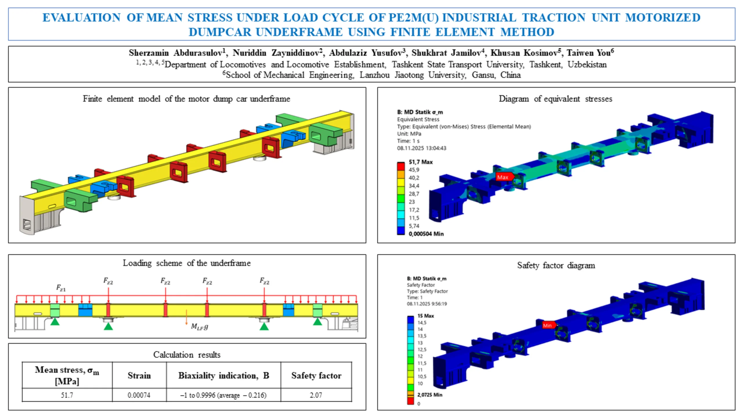
A three-dimensional geometric model of the motorized dumpcar’s underframe was developed in the SolidWorks environment (Fig. 2).
The model integrates the main structural components – the center sill, central support pivot, transverse beams, side brackets, and lateral support elements – into a unified assembly.
During the modelling process, the actual dimensions, cross-sectional geometries, material properties, and locations of welded joints were carefully considered.
As a result, a computational geometric model was constructed that accurately represents the real structural configuration and operating conditions of the motorized dumpcar’s underframe.
The calculated loads acting on the motor dump car underframe (Table 3), including the vertical self-weight and the maximum load from the transported material, were applied to the supporting surfaces of the underframe and to the supporting surfaces of the side brackets as distributed forces (Fig. 3). The self-weight of the underframe was applied at the centre of mass as an acceleration due to gravity ( 9.81 m/s2).
When defining the boundary conditions, the support zones connecting the underframe to the bogies were modelled as Fixed Supports. The applied load corresponded to the vertical static force acting on the motor dump car underframe under operational conditions. This loading configuration simulated the gravitational forces transmitted through the dump body during regular service.
Table 3Calculated acting forces, kN
Self-weight force | Load weight force |
209.7 | 55.8 |
Fig. 2Finite element model of the motor dump car underframe
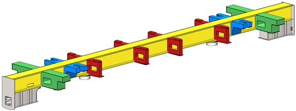
Fig. 3Loading scheme of the underframe
The developed geometric model was imported into the ANSYS Workbench software environment, where a finite element analysis was performed using the Static Structural module. The mechanical properties of the materials used in the simulation corresponded to those presented in Table 1.
For the mesh generation, a combination of tetrahedral and hexahedral elements was employed, with the element size optimised to ensure high computational accuracy. As a result, the generated mesh consisted of 1436845 nodes and 317280 elements.
3. Results and discussion
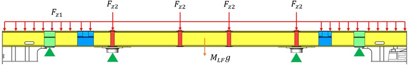
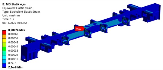
The finite element analysis of the traction unit motorized dumpcar’s underframe revealed that the mean stress during the loading cycle reached approximately 51.7 MPa, while the total strain did not exceed 0.00074 (Table 4). These results indicate that the structural behaviour of the frame remained within the elastic region, confirming that the applied loads were below the material’s yield limit. The obtained stress levels demonstrate a stable response of the frame assembly under static loading, suggesting adequate stiffness and load-bearing capacity.
The analysis of the biaxiality indication parameter, which varied between –1 and 0.9996 with an average value of –0.216, provides further insight into the complex nature of the stress distribution. Localised zones with –1 correspond to areas dominated by pure shear, typically occurring near geometric discontinuities or central support sockets. In contrast, regions with 1 indicate biaxial tension, usually associated with the top surface zones exposed to distributed loads.
On average, the negative biaxiality value (–0.216) implies that the stress state across most of the frame is predominantly uniaxial tension, accompanied by a small compressive component acting in the opposite direction. Such a mixed stress condition is characteristic of welded and bolted steel frame structures subjected to bending and torsional loads. These local stress variations are likely to serve as initiation sites for fatigue cracks during long-term operation, particularly near the junctions between the frame web and support elements.
Overall, the obtained numerical results demonstrate that the frame structure operates under a safe stress level, yet the observed stress gradients and biaxial effects should be considered in fatigue life assessment and residual strength evaluation of industrial traction unit frames.
Table 4Calculation results
Mean stress, [MPa] | Strain | Biaxiality indication, B | Safety factor |
51.7 | 0.00074 | –1 to 0.9996 (average – 0.216) | 2.07 |
Fig. 4Results of finite element analysis
a) Diagram of equivalent stresses
b) Strain diagram

c) Biaxiality indication
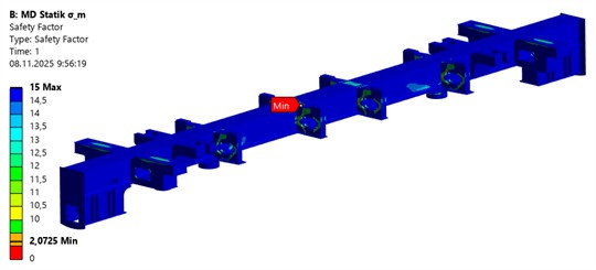
d) Safety factor diagram
4. Conclusions
The numerical and analytical investigations carried out in this study enabled a detailed assessment of the mean stress behaviour in the PE2M(U) industrial traction unit’s motorized dumpcar underframe under static operational load cycles.
Using the finite element method implemented in ANSYS Mechanical, a three-dimensional model of the underframe was developed to examine the distribution of equivalent (von Mises) stresses, total deformations, and stress biaxiality parameters within the main structural elements – namely, the centre sill, cross beams, and central support pivot.
The simulation results revealed that the highest equivalent stresses occur near the junctions between the centre sill and transverse beams, reaching approximately 51.7 MPa, with a minimum safety factor of 2.07, while the maximum total deformation remains below 0.00074. These stress levels correspond to roughly 24 % of the yield strength of 09G2 steel, confirming that the underframe possesses sufficient static strength and a considerable margin of safety. The biaxiality indication values, ranging from −1.0 to +0.9996, indicate complex mixed-stress states that are typical of welded load-bearing structures used in traction vehicles.
From an engineering perspective, the obtained results make it possible to propose several design improvements aimed at increasing the structural durability of the dumpcar underframe:
– Reinforcing the centre sill – cross beam junction.
– Locally thickening the bracket plates in stress concentration areas.
– Optimizing the geometry of welded joints to achieve a more uniform load distribution.
Overall, the study confirms the effectiveness of the proposed FEM-based methodology for evaluating the static stress distribution and structural integrity of industrial traction unit components. Future research will focus on extending the current model to parametric and fatigue analyses, which will allow for a more precise prediction of long-term durability and the residual service life of underframes operating under cyclic loading conditions.
References
-
S. Abdurasulov and N. Zayniddinov, “Increasing the efficiency of operation of industrial traction units in the Republic of Uzbekistan,” in Railway Rolling Stock: Problems, Solutions, Prospects, 2024.
-
S. Abdurasulov, N. Zayniddinov, A. Yusufov, and S. Jamilov, “Analysis of stress-strain state of bogie frame of PE2U and PE2M industrial traction unit,” in E3S Web of Conferences, Vol. 401, p. 04022, Jul. 2023, https://doi.org/10.1051/e3sconf/202340104022
-
S. Abdurasulov, N. Zayniddinov, O. Khamidov, A. Yusufov, and S. Jamilov, “Stress-strain state analysis of cross beam of main frame of industrial electric locomotives PE2M and PE2U,” in The 3rd International Symposium on Civil, Environmental, and Infrastructure Engineering (ISCEIE) 2024, Vol. 3317, No. 1, p. 060011, Jan. 2025, https://doi.org/10.1063/5.0266927
-
V. Rakov, Locomotives and Multiple Unit Rolling Stock of the Soviet Union Railways, 1976-1985. Moscow: Transport, 1990.
-
V. Bratash, Electric Locomotives and Traction Units for Industrial Transport. Moscow: Transport, 1977.
-
L. Balon, V. Bratash, and M. Bichuch, Electric Rolling Stock of Industrial Transport. Moscow: Transport, 1987.
-
E. S. Oganyan, G. M. Volokhov, A. S. Gasyuk, and D. M. Fazliakhmetov, “Calculated experimental evaluation of the operating life of basic locomotive parts for ensuring their safe operation,” Journal of Machinery Manufacture and Reliability, Vol. 47, No. 2, pp. 155–159, Apr. 2018, https://doi.org/10.3103/s1052618818020097
-
E. S. Oganyan, G. M. Volohov, and A. S. Gasyuk, “Justification of safe operation of rolling stock by the lifetime of its bearing structures,” in IOP Conference Series: Materials Science and Engineering, Vol. 1079, No. 5, p. 052089, Mar. 2021, https://doi.org/10.1088/1757-899x/1079/5/052089
-
A. Yusufov, O. Khamidov, N. Zayniddinov, and S. Abdurasulov, “Prediction of the stress – strain state of the bogie frames of shunting locomotives using the finite element method,” in E3S Web of Conferences, Vol. 401, p. 03041, Jul. 2023, https://doi.org/10.1051/e3sconf/202340103041
-
O. Khamidov, A. Yusufov, S. Jamilov, and S. Kudratov, “Remaining life of main frame and extension of service life of shunting Locomotives on railways of Republic of Uzbekistan,” in E3S Web of Conferences, Vol. 365, p. 05008, Jan. 2023, https://doi.org/10.1051/e3sconf/202336505008
-
A. Grishchenko, A. M. Yusufov, and D. N. Kurilkin, “Forecasting the residual service life of the main frame and extending the service life of shunting locomotives JSC “UTY”,” in E3S Web of Conferences, Vol. 460, p. 06032, Dec. 2023, https://doi.org/10.1051/e3sconf/202346006032
-
N. Zayniddinov and S. Abdurasulov, “Durability analysis of locomotive load bearing welded structures,” Science and Innovation, Vol. 1, No. A8, pp. 176–181, 2022.
-
M. Kassner, “Fatigue strength analysis of a welded railway vehicle structure by different methods,” International Journal of Fatigue, Vol. 34, No. 1, pp. 103–111, Jan. 2012, https://doi.org/10.1016/j.ijfatigue.2011.01.020
-
D. Chen, “Strength evaluation of a bogie frame by different methods,” Mechanical Engineering Science, Vol. 1, No. 1, Jul. 2019, https://doi.org/10.33142/me.v1i1.662
-
C.-K. Lee, C.-K. Liu, and Y.-C. Cheng, “Multi-objective optimal design for the railway bogie frame system under stress and fatigue analysis,” in Journal of Physics: Conference Series, Vol. 2793, No. 1, p. 012010, Jul. 2024, https://doi.org/10.1088/1742-6596/2793/1/012010
-
C. Miao, H. Wang, and Y. Song, “The correlation between static strength and fatigue strength test and simulation,” in Journal of Physics: Conference Series, Vol. 2660, No. 1, p. 012042, Dec. 2023, https://doi.org/10.1088/1742-6596/2660/1/012042
-
Y. Abdulaziz, K. Otabek, Z. Nuriddin, J. Shukhrat, and A. Sherzamin, “Application of computer-aided design (CAD) systems when solving engineering survey tasks,” Universum: Technical Sciences, Vol. 108, No. 3, 2023.
-
“Railway applications – Structural requirements of railway vehicle bodies – Part 1: Locomotives and passenger rolling stock (and alternative method for freight wagons),” EN 12663-1:2010, 2023.
-
“Railway applications – Wheelsets and bogies – Method of specifying the structural requirements of bogie frames,” BSI British Standards, London, EN 13749:2021, Apr. 2024.
-
J.-W. Seo, H.-M. Hur, S.-J. Kwon, and K.-H. Moon, “Effect of multiple weld repairs on fatigue strength of bogie frame of railroad vehicle,” Advances in Mechanical Engineering, Vol. 15, No. 11, Nov. 2023, https://doi.org/10.1177/16878132231213596
-
Z. Mukhamedova et al., “Calculating the fatigue strength of load-bearing structures of special self-propelled rolling stock,” Scientific Reports, Vol. 14, No. 1, p. 19205, Aug. 2024, https://doi.org/10.1038/s41598-024-70169-0
-
S. Abdurasulov, N. Zayniddinov, A. Yusufov, S. Jamilov, and F. Khikmatov, “Characteristics of industrial traction units and their load-bearing structures,” Journal of Transport, Vol. 1, No. 4, pp. 45–53, Dec. 2024, https://doi.org/10.56143/2181-2438-2024-4-45-53
-
“Locomotives. Requirements for bearing structure strength and dynamic properties,” GOST 34939-2023, 2023.
-
S. Abdurasulov, N. Zayniddinov, and A. Yusufov, “Requirements for the strength of load-bearing structures of locomotives,” Acta of Turin Polytechnic University in Tashkent, Vol. 13, No. 4, pp. 44–48, 2023.
-
S. Abdurasulov, N. Zayniddinov, and K. Kosimov, “Strength requirements for locomotive load-bearing structures: a literature review,” International Scientific Journal Engineer, Vol. 3, No. 1, pp. 14–18, Mar. 2025, https://doi.org/10.56143/3030-3893-2025-1-14-18
About this article

The authors have not disclosed any funding.
The datasets generated during and/or analyzed during the current study are available from the corresponding author on reasonable request.
The authors declare that they have no conflict of interest.
