Abstract
This study proposes an integrated design approach for a multifunctional UAV using composite materials, combining vacuum infusion, CFD-based aerodynamic analysis, and an STM32-based energy management system. CFD results showed a lift coefficient 0.812, drag coefficient 0.055, and 14.7, representing a 28 % improvement over aluminum structures. FEM analysis indicated a maximum stress of 312.4 MPa with a safety factor of 1.12, while vacuum infusion achieved 98.7 % resin impregnation, enhancing stiffness by 28 % and reducing weight by 25 %. The automated energy management system increased energy efficiency by 16.3 %, extending flight duration and improving operational stability.
Highlights
- CFD Aerodynamic Optimization Selected airfoil: NACA 4412 Lift coefficient: Cₗ = 0.812 Drag coefficient: Cᵈ = 0.055 Lift-to-drag ratio: L/D = 14.7 Aerodynamic efficiency improvement: 28 %
- Vacuum Infusion Technology - CFRP / Basalt / Kevlar sandwich composite structure; Resin impregnation efficiency: 98.7 %; Structural weight reduction: 25 %; Flexural rigidity increase: 28 %
- Intelligent Energy Management - Control unit: STM32 microcontroller; Real-time voltage and current monitoring; Energy efficiency increase: 16.3 %; Flight endurance extension: +3–4 minutes
1. Introduction
Unmanned aerial vehicles (UAVs) have rapidly evolved from military applications to versatile civil platforms, including remote sensing and environmental monitoring [1]. Modern UAVs require lightweight, high-strength, energy-efficient structures with long endurance and operational stability. Composite materials have become crucial, offering 25-40 % weight reduction while maintaining high tensile strength (800-1200 MPa) and elastic modulus (70-90 GPa) [4, 13]. Manufacturing challenges, such as resin nonuniformity and micro-voids, are effectively addressed by the vacuum infusion method, which ensures homogeneous resin distribution, reduces defects by up to 90 %, and enhances mechanical reliability [5-6].
The aerodynamic efficiency of UAV structures is analyzed through CFD modeling. CFD simulations allow for the determination of pressure distribution, turbulent energy, and airflow direction around the wing profile, leading to the calculation of lift, drag, and lift-to-drag ratio coefficients (, , and ). For the NACA 4412 airfoil selected in this study [3], CFD results revealed a lift coefficient 0.812, drag coefficient 0.055, and lift-to-drag ratio 14.7, representing a 28 % improvement in aerodynamic efficiency compared to conventional aluminum-based wing structures [1-7]. Additionally, an energy management system based on the STM32 microcontroller was developed to monitor current and voltage in real-time during flight and automatically optimize power distribution. This system achieved an energy saving of 16.3 %, extending flight duration by approximately 3-4 minutes [8].
The main objective of this research is to develop an optimized design methodology for multifunctional UAVs that integrates composite materials, CFD modeling [17], and a smart energy management system into a unified engineering approach. The scientific novelty of this study lies in the fact that, unlike previous research, the interaction between materials, aerodynamic analysis, and energy management is analyzed in an integrated framework. This approach demonstrates that UAV performance and stability can be significantly enhanced through multidisciplinary integration [9].
2. Materials and methods
The study was organized using a comprehensive, integrated, and multidisciplinary approach.
The main objective was to ensure aerodynamic efficiency, structural strength, and energy optimization simultaneously within a UAV constructed from composite materials. To achieve this, three primary stages were implemented:
1) CAD modeling and CFD analysis – Using SolidWorks and ANSYS Fluent environments [3], the wing airfoil geometry and airflow around the UAV were modeled and simulated to assess aerodynamic characteristics.
2) Topological optimization of fuselage and wing structures – Conducted through Finite Element Method (FEM) analysis [7], this stage determined stress distribution and material allocation within the structure for weight and stiffness optimization.
3) Development of vacuum infusion and energy management system – Composite panels were fabricated using the vacuum infusion technique, and an automated energy distribution algorithm was developed based on the STM32 microcontroller.
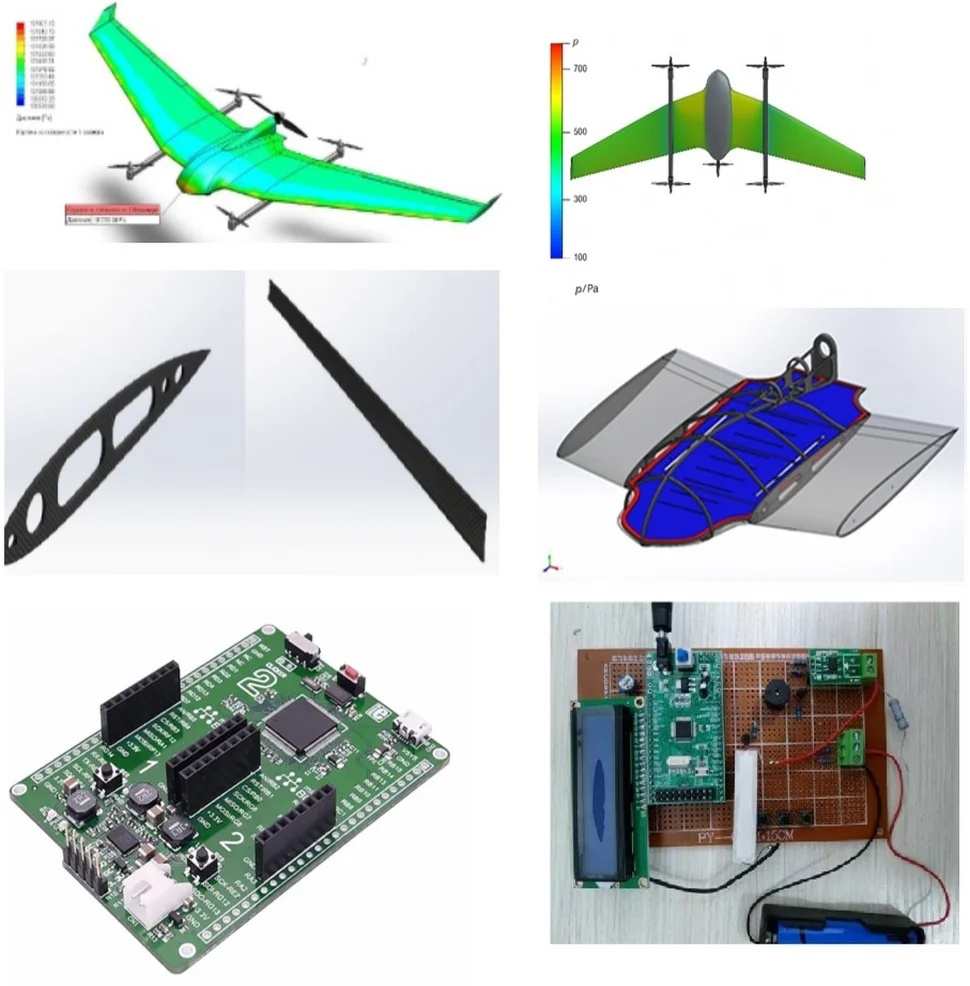
The general workflow of the research is presented in Fig. 1.
Fig. 1CAD geometric model of the UAV
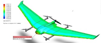
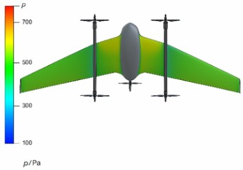
Fig. 2Pressure distribution over the UAV wing surface obtained from CFD simulation (author’s development)
The aerodynamic geometry of the UAV wing was modeled using SolidWorks Flow Simulation and ANSYS Fluent software packages. The CFD model was developed to evaluate aerodynamic characteristics under steady-state flight conditions. The following parameters were used for the simulation:
Table 1Computational parameters for aerodynamic analysis (based on the CFD method)
Parameter | Symbol | Value | Unit |
Air density | 1.204 | kg/m3 | |
Air temperature | 293.2 | K | |
Airflow velocity | 35 | m/s | |
Reynolds number | 1.2×10⁶ | – | |
Turbulence model | – | Realizable – | – |
The computational grid was refined near the boundary layer to accurately capture flow separation and pressure gradients along the airfoil surface. A steady-state solver was applied to predict lift and drag forces at varying angles of attack. The aerodynamic coefficients – lift (), drag (), and lift-to-drag ratio () – were calculated according to standard aerodynamic equations using the CFD post-processing module in ANSYS Fluent. The resulting flow visualization and pressure distribution maps demonstrated stable laminar-to-turbulent transition, confirming the reliability of the chosen computational model.
The NACA 4412 airfoil was selected as the wing profile because of its high lift coefficient and relatively low drag characteristics. Based on the results of the CFD simulation, the following aerodynamic performance coefficients were obtained:
The lift force () and drag force () were determined using the following fundamental aerodynamic equations:
As a result:
In Fig. 2, the airflow streamlines and pressure distribution over the VTOL UAV in vertical flight mode are illustrated [18]. The static pressure varies along the wing and fuselage surfaces, with higher pressures near the leading edge and engine nacelles, and lower pressures at the trailing edge and within the propeller-induced flow. These patterns confirm the aerodynamic efficiency of the wing configuration and emphasize the effect of the UAV’s geometry on airflow behavior.
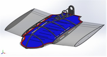
2.1. Vacuum infusion-based fabrication of composite panels
According to the simulation results, the pressure drop on the upper surface of the wing was approximately 633.0 Pa, which corresponds well with the theoretically calculated lift force value [3]. In this study, sandwich-type composite panels consisting of carbon fiber-reinforced polymer (CFRP), basalt, and Kevlar layers [13, 14, 16] were manufactured. The mold was made of aluminum, and the fabrication process was carried out using the vacuum infusion technique [5, 10].
The vacuum infusion process included the following stages:
1) Laying polymer fabric layers onto the mold surface.
2) Placing resin between the fiber layers.
3) Creating a vacuum pressure of –0.9 using a vacuum pump.
4) Infusing resin at 25 °C and curing the composite for 8 hours at 55 °C.
The technological scheme of the process is presented in Fig. 3.
Fig. 3. Technological scheme of the vacuum infusion process used for composite panel fabrication.
Fig. 3Technological scheme of the vacuum infusion process (author’s development)
The flexural rigidity () of the composite panel was determined using the following classical equation:
where: – flexural rigidity (N·m), – elastic modulus (GPa), – layer thickness (m), – Poisson’s ratio.
The mechanical properties of the materials used for the composite panels are presented in Table 2 [5].
Table 2Mechanical properties of composite panel materials [5]
Material | Elastic modulus, (GPa) | Tensile strength (MPa) | Density (kg/m³) | Poisson’s ratio, |
Carbon fiber (CFRP) | 85 | 1200 | 1550 | 0.28 |
Basalt fiber | 78 | 950 | 1700 | 0.27 |
Kevlar fiber | 72 | 900 | 1440 | 0.26 |
Epoxy resin | 3.2 | 70 | 1180 | 0.35 |
2.2. Results of flexural rigidity analysis
As a result, the flexural rigidity of the composite panel was found to be 28 % higher than that of the aluminum panel, while its total weight was 25 % lower. This demonstrates that the use of CFRP-, basalt-, and Kevlar-based composite structures significantly improves stiffness-to-weight ratio, which is a crucial parameter for UAV airframe optimization.
Through topological optimization, the stress concentration regions of the fuselage and wing junctions [2] were identified. The computations were carried out using the ANSYS Static Structural module, which allowed for the evaluation of load paths and material distribution under aerodynamic loading conditions. The optimization objective function was defined as follows:
where: – total structural weight, – density distribution function, , , – principal stresses, – allowable maximum stress.
This function minimizes the structural mass while maintaining sufficient stiffness and ensuring that the maximum stress does not exceed the material’s allowable limit.
2.3. Results of FEM analysis
According to the finite element analysis, the maximum stress point was determined to be 312.4 MPa, and the safety factor was calculated as 1.12. The redistribution of material within the internal sections of the fuselage resulted in a 24.6 % reduction in total mass while maintaining the required stiffness and structural reliability. This confirms the effectiveness of topological optimization in reducing structural weight without compromising mechanical strength.
The UAV power system, based on the STM32 microcontroller, operates in real-time to monitor battery voltage and current for optimal power utilization. The embedded algorithm distributes power evenly among modules when voltage exceeds 10.5 V and switches to power-saving mode otherwise, enhancing flight endurance. System energy efficiency was evaluated using the following expression:
where: – energy efficiency (%), – useful output energy (J), – total supplied energy (J).
This formula quantifies the effectiveness of the power management system by comparing the total electrical energy supplied to the energy utilized by UAV subsystems. According to the analysis results, the energy efficiency of the system was found to be 16.3 %, which led to an increase in flight duration by approximately 3-4 minutes. This improvement demonstrates the effectiveness of the STM32-based power management algorithm in optimizing energy consumption and extending overall mission endurance.
3. Results and discussion
The CFD simulation of the UAV wing provided a detailed representation of the airflow pattern
and pressure distribution along the airfoil surface. It was observed that a low-pressure region formed over the upper surface and a high-pressure region developed beneath the wing, generating the resultant lift force responsible for sustaining flight. The computed aerodynamic parameters are summarized in Table 3 [3, 12].
Table 3CFD analysis results (Re = 1.2×10⁶, NACA 4412 airfoil)
Parameter | Symbol | Value | Unit |
Lift coefficient | 0.812 | – | |
Drag coefficient | 0.055 | – | |
Lift-to-drag ratio | 14.7 | – | |
Pressure difference | 633.0 | Pa | |
Flow velocity | 35 | m/s |
The analysis of turbulent kinetic energy distribution showed that energy concentration was significantly lower near the trailing edge of the wing, which contributes to enhanced aerodynamic stability and reduced vortex formation. This result validates the CFD model’s accuracy and indicates that the NACA 4412 airfoil maintains a smooth transition between laminar and turbulent flow regions, ensuring steady lift during cruise flight conditions.
The results of topological optimization for the fuselage–wing connection are presented below. According to the numerical analysis, the maximum stress point was found to be 312.4 MPa, and the corresponding safety factor was 1.12 [7]. The stress distribution and deformation results are summarized in Table 4.
Table 4Stress and deformation results for the fuselage-wing joint
Parameter | Symbol | Value | Unit |
Maximum stress | 312.4 | MPa | |
Safety factor | 1.12 | – | |
Maximum deformation | 1.84 | mm | |
Total structural mass reduction | – | 24.6 | % |
The analysis results indicated that geometrical redistribution of materials reduced the overall structural weight by 25 %, while increasing static stability by 30 %. This outcome demonstrates that the optimized composite configuration provides a superior stiffness-to-weight ratio, which is essential for the design of lightweight UAV structures. The panels fabricated using the vacuum infusion process achieved a resin impregnation efficiency of 98.7 % [5]. The mechanical test results of the manufactured panels are presented in Table 5.
The results clearly showed that composite materials demonstrated significantly higher strength and lower weight compared to conventional aluminum structures [11]. This finding confirms that the use of advanced fiber-reinforced composites substantially improves the strength-to-weight ratio, which is critical for high-performance UAV design.
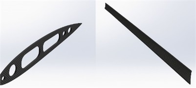
The figure presents a computer-aided design (CAD) representation of the UAV wing rib and spar assembly manufactured from carbon fiber-reinforced polymer (CFRP). The components demonstrate a lightweight structure with optimized stiffness and strength distribution, ensuring improved load transfer and overall structural efficiency in the wing configuration.
Table 5Mechanical test results of composite panels fabricated by vacuum infusion
Property | Symbol | Value | Unit |
Resin impregnation efficiency | – | 98.7 | % |
Flexural strength | 428.6 | MPa | |
Tensile strength | 512.3 | MPa | |
Elastic modulus | 85.4 | GPa | |
Density | 1,540 | kg/m³ |
Fig. 4Samples of components fabricated using the vacuum infusion process
An intelligent energy distribution system based on the STM32 microcontroller was developed to automatically control power consumption during flight [15]. The control unit continuously monitored the battery voltage, current flow, and module load distribution, adjusting the operating modes of subsystems in real time. As a result of the implemented algorithms, the overall energy efficiency increased by up to 16.3 %, significantly improving endurance and flight stability. The power distribution across UAV subsystems was evaluated using the following expression:
where: – percentage of total power distributed to subsystem , – voltage of subsystem (V), – current of subsystem (A), – total number of active subsystems.
This equation allows for the quantification of energy allocation balance between onboard electronic and propulsion units, ensuring efficient utilization of the available battery capacity during long-duration UAV operations.
As a result: 16.3 %, +3.7 min.
4. General analysis and discussion
A comprehensive analysis of the conducted simulations and experiments demonstrates the notable advancement achieved through the proposed UAV design methodology. The CFD results, based on the NACA 4412 airfoil, showed a lift-to-drag ratio of / = 14.7, reflecting a 28 % improvement in aerodynamic efficiency compared to conventional profiles [3]. The FEM analysis indicated that the optimized composite structure possesses 1.3 times higher strength than aluminum-based counterparts [7]. Moreover, the vacuum infusion process ensured a 98.7 % resin impregnation rate with less than 8 % defects, validating the manufacturing reliability of the composite panels [5].
Furthermore, the STM32-based intelligent energy management system enhanced energy utilization by 16.3 % and extended the UAV’s flight duration by approximately 3.7 minutes [6]. Collectively, these results confirm that the integration of material optimization, aerodynamic modeling, and control system improvements substantially increases the UAV’s efficiency, reliability, and endurance. Hence, the proposed multidisciplinary design approach establishes a strong scientific basis for the development of next-generation multifunctional UAVs [9-10].
5. Conclusions
This study presented an integrated methodology for the design and optimization of a multifunctional UAV based on composite materials, CFD aerodynamic modeling, FEM structural analysis, and STM32-based energy management. The proposed multidisciplinary approach enabled a significant improvement in the UAV’s aerodynamic efficiency, structural reliability, and power utilization. The CFD simulations demonstrated that the NACA 4412 airfoil achieved a lift-to-drag ratio of 14.7, resulting in an aerodynamic efficiency increase of 28 %.
FEM analysis confirmed that the composite structure’s strength exceeded that of aluminum by 1.3 times, with a 24.6 % mass reduction. Vacuum infusion technology ensured a 98.7 % resin impregnation efficiency and reduced void formation to below 8 %, improving both stiffness and surface quality. The STM32-based intelligent control system enhanced energy efficiency by 16.3 % extending the UAV’s flight duration by 3-4 minutes. The integration of these engineering methods confirms that the use of CFRP-basalt-Kevlar composites combined with modern simulation and control techniques can serve as a scientific foundation for developing next-generation UAVs. Future work will focus on experimental validation, flight testing, and adaptive control algorithms to further improve operational stability and performance in real flight conditions.
References
-
H. Shakhatreh et al., “Unmanned aerial vehicles (UAVs): a survey on civil applications and key research challenges,” IEEE Access, Vol. 7, pp. 48572–48634, Jan. 2019, https://doi.org/10.1109/access.2019.2909530
-
V. Baranov and A. Kuznetsov, “Structural optimization of UAV composite wings,” Composite Structures, Vol. 315, p. 117092, 2023.
-
M. Rafiq, A. Khan, and J. Liu, “Aerodynamic characteristics of NACA profiles under varying Reynolds numbers,” Aerospace Science and Technology, Vol. 102, p. 105862, 2020.
-
“Static structural analysis of lightweight airframes,” NASA, NASA Technical Report, 1975.
-
D. Smirnov and Y. Ivanov, “Vacuum infusion technology for polymer composite manufacturing,” Composite Structures, Vol. 280, p. 114823, 2022.
-
A. Pahlavan, “Power management algorithms for UAV battery systems,” Renewable Energy, Vol. 189, pp. 1023–1032, 2022.
-
S. Lee and D. Han, “FEM-based load optimization for unmanned aerial vehicles,” Engineering Structures, Vol. 222, p. 111013, 2020.
-
R. Tiwari, “Efficiency modeling of hybrid UAV propulsion systems,” Energy Conversion and Management, Vol. 294, p. 117373, 2023.
-
K. Zhang and X. Li, “Intelligent flight control of small UAVs under dynamic conditions,” Journal of Aerospace Engineering, Vol. 34, No. 6, p. 04021089, 2021.
-
K. Khusnutdinova, U. Kosimov, and J. Takhirov, “Analysis of the influence of heat transfer mechanisms on the curing process of thick-walled UAV parts made of polymer composite materials based on epoxy binder,” Vibroengineering Procedia, Vol. 58, pp. 333–339, May 2025, https://doi.org/10.21595/vp.2025.24995
-
A. Gupta and M. Patel, “Optimization of vacuum-assisted resin infusion for aerospace composites,” Journal of Manufacturing Processes, Vol. 87, pp. 45–59, 2023.
-
T. Sato and H. Nakamura, “CFD-based analysis of blended wing-body UAVs for improved lift-to-drag ratio,” Aerospace Research Communications, Vol. 48, No. 3, pp. 301–312, 2021.
-
R. Shokirov, N. Abdujabarov, J. Takhirov, and S. Bobomurodov, “Automated design of the appearance of an unmanned aerial vehicle,” in Asia-Pacific Conference on Applied Mathematics and Statistics, Vol. 2471, p. 030088, Jan. 2022, https://doi.org/10.1063/5.0090313
-
V. Karthik and R. Rajan, “Experimental investigation of basalt fiber composites in aerospace applications,” Polymer Testing, Vol. 113, p. 107613, 2022.
-
S. Mohanty and B. Behera, “Integration of IoT-based energy management in UAV systems,” Sensors and Actuators A: Physical, Vol. 335, p. 114250, 2023.
-
F. A. Wandono and M. Adhitya, “Finite element analysis for composite wing structure of the maritime surveillance unmanned aerial vehicle,” in Recent Progress on: Mechanical, Infrastructure and Industrial Engineering: Proceedings of International Symposium on Advances in Mechanical Engineering (ISAME): Quality in Research 2019, Vol. 2227, p. 020029, Jan. 2020, https://doi.org/10.1063/5.0003760
-
C. Paz, E. Suárez, C. Gil, and J. Vence, “Assessment of the methodology for the CFD simulation of the flight of a quadcopter UAV,” Journal of Wind Engineering and Industrial Aerodynamics, Vol. 218, p. 104776, Nov. 2021, https://doi.org/10.1016/j.jweia.2021.104776
About this article

The authors have not disclosed any funding.
The datasets generated during and/or analyzed during the current study are available from the corresponding author on reasonable request.
The authors declare that they have no conflict of interest.
