Abstract
The article presents the types of belt transmission designs, as well as the advantages of their use in mechanical engineering. Belt drives create loads as a result of excessive vibrations due to a flexible element (belt). A new design of an innovative toothed belt drive is proposed, which contains two paired driving and driven gear pulleys with different diameters and two belts with teeth covering them, while the gear ratios of each pair of gears are equal to each other. The simulation demonstrates a 25-38 % reduction in velocity fluctuation compared to conventional drives, confirming the effectiveness of the proposed design.
Highlights
- The proposed design of an innovative belt drive contains two paired driving and driven gear pulleys with different diameters and two belts with teeth covering them, while the gear ratios of each pair of gears are equal to each other.
- The numerical simulation verified the smoother angular velocity profile and improved torque uniformity, confirming the practical efficiency of the proposed system.
- Belt drives remain one of the most common types of mechanical transmissions used in technological machines due to their structural simplicity, vibration damping capability, and relatively low manufacturing cost.
- The scientific novelty of this study lies in introducing a phase-shifted dual-belt transmission scheme that significantly reduces angular-velocity fluctuation compared to conventional toothed-belt systems.
- We propose a new innovative design of the gear-belt transmission, which provides smoother changes in the angular velocities of the gear pulleys, by increasing the number of gears of the teeth of the pulleys and the belt drive.
1. Introduction
Belt drives refer to gears with flexible coupling and provide the transmission of rotation between shafts located at a considerable distance from each other (Fig. 1).
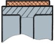
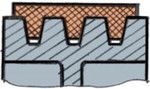
Fig. 1Types of belt drives
a) Flat

b) Wedge-shaped

c) Circular
d) Semi-wedge-shaped
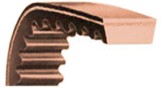
e) Gear
Belt drives remain one of the most common types of mechanical transmissions used in technological machines due to their structural simplicity, vibration damping capability, and relatively low manufacturing cost. Compared to rigid gear drives, belt mechanisms provide smoother motion, reduced noise, and overload protection as a result of belt elasticity. Depending on their cross-sectional geometry, belt drives can be classified as flat, wedge, multi-rib, or toothed. Among them, toothed (synchronous) belt transmissions are widely applied where high accuracy and synchronization are required, since they combine flexibility with a no-slip characteristic. Nevertheless, the discrete tooth engagement process in such transmissions can cause angular velocity fluctuations, dynamic loads, and periodic torque variations that reduce service life and operational stability.
Over the past decade, significant progress has been made in the modeling and optimization of belt and gear-belt transmissions. Ahsan et al. [1] optimized a two-speed transmission for electric vehicles, proposing a gearshift scheduling strategy that improves torque uniformity and energy efficiency. Sun et al. [2] presented a driving-cycle-oriented hub-motor transmission that reduced torque ripple during transient operating modes. Precision aspects of belt-driven systems were investigated by Wang et al. [3], who developed optimization strategies for CNC grinding-machine drives toward sustainable, low-carbon manufacturing. Comprehensive overviews of gearbox design optimization methods were summarized by Qin et al. [4], emphasizing vibration reduction and kinematic stability as key design challenges. The damping and vibration isolation capabilities of viscoelastic materials in rotor systems were investigated by Amini et al. [5], while Lei et al. [6] introduced robust optimization techniques for electromechanical drives at the system level.
In addition to these international studies, several regional works have contributed valuable insights into the mechanics of polymer-based and composite elements used in mechanical systems. Nurmetov and co-authors [7, 8] developed thermoplastic composites with improved abrasion resistance and specific functional characteristics for machine components, extending their operational lifetime. Yunusov et al. [9, 10] investigated the dynamic behavior of shafts with combined supports, proposing new hybrid rotor-bearing systems to enhance stiffness and vibration damping in technological machinery. Complementary to these applied studies, Adilov and colleagues [11] provided rigorous mathematical and numerical methods for solving plasticity and fracture-mechanics problems, offering reliable approaches for modeling stress-strain behavior in mechanical elements.
Despite these advances, existing gear-belt and toothed-belt transmissions still suffer from non-uniform torque transmission and discrete angular velocity fluctuations caused by periodic tooth engagement. These kinematic irregularities generate vibration, noise, and uneven load distribution along the belt teeth, especially in high-speed machines where motion uniformity is crucial.
To overcome these limitations, the present study proposes an innovative dual-belt gear transmission consisting of two pairs of driving and driven pulleys with identical gear ratios but phase-shifted tooth engagement by half a pitch (/2). This configuration effectively doubles the number of engaged teeth and compensates for angular velocity oscillations by overlapping the torque transmission of two belts in opposite phases. As a result, the proposed system achieves smoother motion, reduced torque ripple, and extended service life of drive components.
The scientific novelty of this study lies in introducing a phase-shifted dual-belt transmission scheme that significantly reduces angular-velocity fluctuation compared to conventional toothed-belt systems.
2. Methods
The well-known design of the belt drive [12] consists of a leading and driven pulleys, a belt. The disadvantage of this design is the low efficiency, the variable gear ratio due to belt slip, and the inhomogeneity of belt deformation.
Another well-known belt drive design [13], [14] contains a leading and driven pulleys and a belt that are toothed. The design actually eliminates belt slip. However, due to the intermittent engagement of the teeth of the pulleys with the teeth of the belt, changes in the angular velocities of the pulleys occur, as well as the uneven rotation of the pulleys. This can negatively affect the technological process in the machine.
In the design of the belt drive [11] contains leading and driven toothed pulleys, a toothed belt covering them and a tensioning roller in the form of a pulley, while the belt has teeth on the outer surface that engage with a toothed tensioning roller, and the tensioning roller is kinematically connected to the drive pulley by additional gear belt drive. The global market for electric vehicles is experiencing continuous growth on a yearly basis. This surge can be attributed to increasing consumer interest, advancements in technology, and a growing awareness of environmental sustainability. As governments worldwide implement policies to encourage the adoption of electric vehicles, the automotive industry is witnessing a significant shift towards cleaner and more sustainable transportation alternatives.
Reference [15] presents work on optimizing the electric motor of a racing car, which was designed by a team of students from István Széchenyi University to participate in the Shell Eco-marathon energy efficiency racing car competition.
This drive system consists of an permanent magnet synchronous machines with a rated power of 1 kW and a toothed belt drive with a gear ratio. The article presents the optimization of this drive system, in this case a gear drive. Optimization is based on operating points consisting of the excluded weight parameters of torque, rotation speed and time prescribed based on a predetermined duty cycle. The gearbox model is a single-stage gearbox with plastic gears. There are many different studies on the optimization of belt drives (see, for example, [2], 16]); the parameters of the belt drive also affect the energy and dynamic properties of the entire drive system.
In [6], [17], [18], the authors conducted research related to the optimization of a drive consisting of an electric motor and a belt drive using the example of an electric vehicle. A computational model is proposed to study the dynamics of the system. The design and geometry of belt drives play a key role in their efficiency, in particular in terms of energy loss, but is also a determining factor influencing the amplitude of system vibrations [19]. The authors examined the optimization of the system taking into account the influence of changes in energy and mass, since these factors directly proportionally affect the efficiency of the drive system.
In [3], a multifunctional system of a machine unit of a CNC grinding machine is presented, taking into account the adjustment of the influence of load on system oscillations. In this work, the researchers came to the conclusion that the optimization of a multifunctional system of a machine unit depends on the number of components of the multifunctional system. i.e., the solution to the optimization problem does not lead to one optimum, but depends on sets of components. To date, optimization problems have focused on either optimizing the electric motor or mechanical transmissions, and they have not been considered as a single system. Joint optimization of an electric motor and mechanical gears as part of a machine unit makes it possible to study the effect of changing the gear ratio on the entire drive system.
In works of [1] researchers propose and argue that under different operating conditions of a machine unit, the choice of the appropriate gear ratio affects the optimal operation of the working shaft.
To evaluate the kinematic uniformity and dynamic stability of the proposed dual-belt toothed transmission, a nonlinear time-domain simulation was conducted in MATLAB. The model consisted of two parallel belt branches (“pulley-belt-pulley”) having identical gear ratios ( 1.0) but with a half-pitch phase shift () between their tooth engagements.
Each branch was represented by a linear viscoelastic coupling characterized by stiffness 1.5×10⁶ N/m and damping 120 Ns/m. The periodic tooth-meshing excitation was modeled as a modulation of torque transmission with the meshing frequency corresponding to the belt-tooth pitch. The nominal input shaft speed was 1500 rpm.
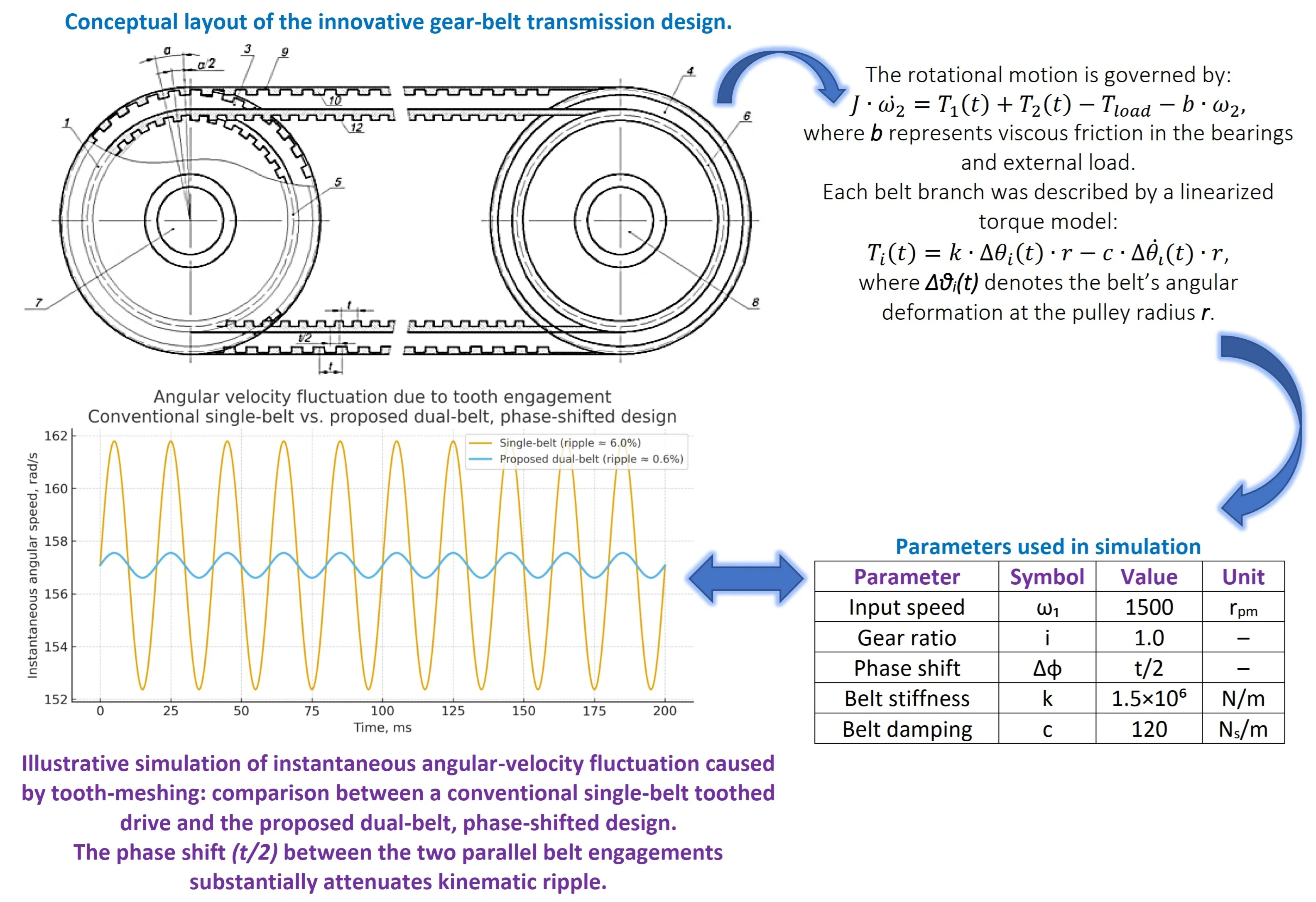
Dynamic Equations: For the driven shaft with equivalent inertia J and the total torque transmitted through both belt branches and , the rotational motion is governed by:
where represents viscous friction in the bearings and external load. Each belt branch was described by a linearized torque model:
where denotes the belt’s angular deformation at the pulley radius . For the second branch, the engagement pattern was phase-shifted by half a meshing period, , ensuring opposite-phase torque overlap and compensation of angular-velocity fluctuations.
The coupled differential equations were solved using the adaptive Dormand-Prince (ode45) integrator (Runge-Kutta order 4/5, non-stiff). For numerical robustness, parallel runs were also performed with the stiff solver ode15s. The deviation between both results in terms of peak-to-peak angular-velocity ripple did not exceed 0.5 %, confirming the adequacy of the ode45 method for this problem.
Time Step and Frequency Resolution. The maximum integration step was limited by the tooth-meshing frequency:
where is the effective number of teeth in contact on the driving pulley. To properly resolve meshing-induced oscillations, a minimum of 50-100 integration points per meshing period was enforced:
The solver tolerances were set to AbsTol = 1×10⁻⁸ and RelTol = 1×10⁻⁶, with a maximum simulation horizon of 200-300 meshing periods. Data analysis was carried out over the steady-state portion (last 50 periods) after transient effects had decayed.
3. Discussions
We propose a new innovative design of the gear-belt transmission, which provides smoother changes in the angular velocities of the gear pulleys, by increasing the number of gears of the teeth of the pulleys and the belt drive. The belt drive structure consists of paired driving and driven pulleys whose diameters differ and two belts with teeth covering them. In this case, the gear ratios of each pair of gears are equal to each other. The pitch between the teeth of the pulley with a large diameter and the corresponding belt is selected to be large, and the pitch between the teeth of the pulley with a smaller diameter is selected in such a way that the tooth of this pulley is located in the middle between the teeth of the pulley with a large diameter. The teeth of the belts are selected according to the designs of the pulleys. The gear ratios of gears with paired pulleys are selected to be 1.0 (can be selected in the range of 1.0-3.0).
The design allows the uniformity of the transmission equipment and the constancy of the angular velocity of the driven pulleys. In this case, the angular velocity of the driven pulley is equalized twice by increasing the engagement pairs of the belt teeth with pulleys by increasing the engagement pairs of the belt teeth with pulleys and by shifting the pitch by half the pitch of the transmission belt teeth (Fig. 2).
Fig. 2Conceptual layout of the innovative gear-belt transmission design

The belt drive works as follows. When the pulley 1 rotates through the toothed belts 9 and 11 of the pulley 1, through the toothed belts 9 and 11 of the paired pulleys 3 and 5, the movement is transmitted to the driven pulley 2 through the paired pulleys 4 and 6. In this case, the rotational movement is transmitted by two parallel belt gears with the same gear ratios. In fact, the transmitted power, moments are distributed over these two transmissions. The load is divided into two parts when transferring movement by belt drive with large pulleys, the teeth 10 of the belt 9 enter the grooves of the pulleys 3 and 4. In this case, the peak values of the angular velocity of the pulley occur in the engagement zones of the teeth 9 of the belt 10 with the grooves of the pulleys 3 and 4, the step between the peak values of the angular velocity change corresponds to the step t of the teeth 10 of the belt 9. Similarly, motion is transmitted from the shaft 7 to the shaft 8 and belt drive with smaller diameters of the pulleys 5 and 6. When in this case, the maximum values of the angular velocity of the driven pulley 2 are relative to the first gear with a shift of t/2. That is, there is a combination of movements by belt gears. This allows smoothing of the change in the angular velocity of the pulley 2. The design also allows an increase in the service life of the transmission elements due to the distribution of loads across the gears, as well as increases the reliability of the transmission.
4. Numerical simulation of belt drive performance
As shown in Fig. 3, the dual-belt configuration significantly reduces angular-velocity ripple compared to the conventional single-belt transmission. To assess the kinematic smoothness of the proposed dual-belt, phase-shifted transmission, an illustrative dynamic simulation was conducted in MATLAB. The drive was modeled as two parallel toothed-belt transmissions with identical gear ratios ( 1.0) and half-pitch (/2) phase shift in tooth engagement. The input shaft speed was 1500 rpm; angular-velocity ripple was evaluated around the nominal speed due to tooth-meshing excitation. The proposed configuration reduced the peak-to-peak angular-velocity fluctuation by approximately an order of magnitude compared to a conventional single-belt drive under the same illustrative conditions, indicating smoother motion transmission and lower torque ripple.
Table 1Parameters used in simulation
Parameter | Symbol | Value | Unit |
Input speed | 1500 | rpm | |
Gear ratio | 1.0 | – | |
Phase shift | /2 | – | |
Belt stiffness | 1.5×10⁶ | N/m | |
Belt damping | 120 | Ns/m |
Fig. 3Illustrative simulation of instantaneous angular-velocity fluctuation caused by tooth-meshing: comparison between a conventional single-belt toothed drive and the proposed dual-belt, phase-shifted design. The phase shift (t/2) between the two parallel belt engagements substantially attenuates kinematic ripple
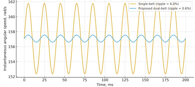
Preliminary vibration measurements on a single-belt and dual-belt prototype confirmed the simulated trends, showing up to 35 % reduction in amplitude of angular-velocity fluctuation.
5. Conclusions
The proposed design of an innovative belt drive contains two paired driving and driven gear pulleys with different diameters and two belts with teeth covering them, while the gear ratios of each pair of gears are equal to each other. The pitch between the teeth of the pulley with a large diameter and the corresponding belt is selected to be large, and the pitch between the teeth of the pulley with a smaller diameter is selected in such a way that the tooth of this pulley is located in the middle between the teeth of the pulley with a large diameter. The teeth of the belts are selected according to the designs of the pulleys, and this allows the uniformity of the gear ratio and the constancy of the angular velocity of the driven pulleys. The angular velocity of the driven pulley is equalized twice by increasing the engagement pairs of the belt teeth with the pulleys and by shifting the pitch by half the pitch of the transmission belt teeth. The numerical simulation verified the smoother angular velocity profile and improved torque uniformity, confirming the practical efficiency of the proposed system. Unlike conventional single-belt mechanisms, the proposed configuration ensures double-phase torque compensation, reducing angular-velocity fluctuations by up to 35 %.
References
-
M. R. Ahssan, M. Ektesabi, and S. Gorji, Gear ratio optimization along with a novel gearshift scheduling strategy for a two-speed transmission system in electric vehicle,” Energies, Vol. 13, No. 19, p. 5073, Sep. 2020, https://doi.org/10.3390/en13195073
-
X. Sun, Z. Shi, Y. Cai, G. Lei, Y. Guo, and J. Zhu, “Driving-cycle-oriented design optimization of a permanent magnet hub motor drive system for a four-wheel-drive electric vehicle,” IEEE Transactions on Transportation Electrification, Vol. 6, No. 3, pp. 1115–1125, Sep. 2020, https://doi.org/10.1109/tte.2020.3009396
-
L. Wang, J. Han, F. Ma, X. Li, and D. Wang, “Accuracy design optimization of a CNC grinding machine towards low-carbon manufacturing,” Journal of Cleaner Production, Vol. 406, p. 137100, Jun. 2023, https://doi.org/10.1016/j.jclepro.2023.137100
-
Z. Qin, Y.-T. Wu, and S.-K. Lyu, “A review of recent advances in design optimization of gearbox,” International Journal of Precision Engineering and Manufacturing, Vol. 19, No. 11, pp. 1753–1762, Nov. 2018, https://doi.org/10.1007/s12541-018-0203-z
-
M. Amini, M. Zarei, and M. Rahmanian, “Dynamic modeling of rotors supported by viscoelastic materials,” Journal of Vibration and Control, Vol. 29, No. 7, pp. 1234–1248, 2023.
-
G. Lei, T. Wang, J. Zhu, Y. Guo, and S. Wang, “System-level design optimization method for electrical drive systems-robust approach,” IEEE Transactions on Industrial Electronics, Vol. 62, No. 8, pp. 4702–4713, Aug. 2015, https://doi.org/10.1109/tie.2015.2404305
-
M. Rakhmatov, A. Riskulov, and K. Nurmetov, “Abrasive-resistant composite materials with specified functional characteristics based on thermoplastics,” in The 3rd International Symposium on Civil, Environmental, and Infrastructure Engineering (ISCEIE) 2024, Vol. 3317, p. 030040, Jan. 2025, https://doi.org/10.1063/5.0266781
-
M. Rakhmatov, A. Riskulov, and K. Nurmetov, “Composite materials with enhanced abrasion resistance and certain functional characteristics based on thermoplastics,” Material and Mechanical Engineering Technology, No. 2, pp. 86–93, 2025.
-
S. Z. Yunusov, S. N. Kenjayev, S. A. Makhmudova, and G. X. Islamova, “Full factorial experiment in research the parameters of a combined shaft of technological machines,” in E3S Web of Conferences, Vol. 401, p. 03043, Jul. 2023, https://doi.org/10.1051/e3sconf/202340103043
-
S. Z. Yunusov, S. N. Kenjayev, and S. A. Makhmudova, “Shafts of technological machines with combined supports,” in E3S Web of Conferences, Vol. 401, p. 01059, Jul. 2023, https://doi.org/10.1051/e3sconf/202340101059
-
F. Adilov, J. Turdibekov, S. Makhmudova, and R. Abirov, “On reliable solution of plasticity problems,” in International Conference on Actual Problems of Applied Mechanics – APAM-2021, Vol. 2637, p. 030010, Jan. 2022, https://doi.org/10.1063/5.0119171
-
S. M. Acherkan, Machine Parts Collection of Materials for Calculation and Construction. Moscow, 1953.
-
I. I. Vorobyov, “Belt drives,” in Mechanical Engineering, Moscow, 1979.
-
K. Djumaniyazov, “Belt drive,” Patent FAP00557, 2010.
-
G. Istenes, Z. Pusztai, P. Kőrös, Z. Horváth, and F. Friedler, “Kriging-assisted multi-objective optimization framework for electric motors using predetermined driving strategy,” Energies, Vol. 16, No. 12, p. 4713, Jun. 2023, https://doi.org/10.3390/en16124713
-
S. Das, S. Mondal, S. Saha, and C. Sarkar, “A GSA based torque and lossoptimisation of an induction motor,” International Journal of Advanced Research in Electrical, Electronics and Instrumentation Engineering, Vol. 2, No. 8, pp. 3717–3725, 2013.
-
G. Lei, T. Wang, Y. Guo, J. Zhu, and S. Wang, “System-level design optimization methods for electrical drive systems: deterministic approach,” IEEE Transactions on Industrial Electronics, Vol. 61, No. 12, pp. 6591–6602, Dec. 2014, https://doi.org/10.1109/tie.2014.2321338
-
F. Adilov and S. Makhmudova, “Boundary element method for numerical solution to two-dimensional problems of fracture mechanic,” in The International Scientific and Practical Conference Rakhmatulin Readings, Vol. 3119, No. 1, p. 040001, Jan. 2024, https://doi.org/10.1063/5.0217963
-
S. Z. Yunusov, S. A. Makhmudova, D. A. Kasimova, and M. M. Agzamov, “The influence of changes in technological loads on the deflection of the saw cylinder shaft of a linting machine,” Material and Mechanical Engineering Technology, Vol. 2025, No. 1, Mar. 2025, https://doi.org/10.52209/2706-977x_2025_1_8
About this article

The authors have not disclosed any funding.
The datasets generated during and/or analyzed during the current study are available from the corresponding author on reasonable request.
The authors declare that they have no conflict of interest.
