Abstract
Taking a GTF star transmission gearbox as the research object, this paper innovatively introduces the Westgard decision diagram, which is widely used in medical clinical trials, and combines "relative error distance method of speed, transmission ratio and meshing force" to build a performance evaluation method of gearbox model based on multi-body dynamics. At the same time, the translation-torsional dynamics model of the gearbox is established by using the lumped mass theoretical method, and the key parameters such as output speed, gear meshing force and bearing vibration acceleration are obtained by the analysis of the two models. Comparing the simulation results of the multi-body dynamics model selected by the performance evaluation method with the analysis results of the concentrated parameter method, it can be seen that the performance of the multi-body dynamics model selected by the performance evaluation method is reliable and effective, and the analysis accuracy and analysis efficiency can be taken into account. The maximum absolute error of meshing force is 2.5771 N, and the absolute error of vibration acceleration at the bearing of input shaft and output shaft is controlled within 0.08 m·s-2 and 0.1 m·s-2, respectively. The model performance evaluation method proposed in this paper effectively solves the problem of the balance between simulation efficiency and accuracy of the traditional gearbox dynamics model, provides a new technical path for the performance evaluation of complex gear transmission systems, and provides a reliable theoretical basis and technical support for the design and optimization of gear transmission systems of high-end equipment such as aeroengines, and has important engineering application value.
Highlights
- Various multi-body dynamics models of GTF star gearboxes are screened out based on the Westgard decision diagram, and a simulation model that takes into account of the analysis efficiency and accuracy is obtained, which overcomes the limitation of the evaluation of a single simulation index.
- By comparing the simulation results of the multi-body dynamics model selected by the performance evaluation method with the analysis results of the centralized parameter method, it can be known that this method is reliable and effective, and can take into account both analysis accuracy and analysis
- The Westgard decision diagram can be used to quickly screen the multi-body dynamics models of complex mechanical systems, which has high simulation accuracy and efficiency, and improves the correctness and engineering practicability of simulation analysis.
1. Introduction
The geared turbofan engine (GTF) introduces a decelerating star-driven gearbox (hereinafter referred to as the gearbox) between the low-pressure rotor and the fan, and by balancing the difference in rotational speeds between the low-pressure rotor and the fan, the engine has advantages of small size, high thrust and high efficiency. The dynamics of the gearbox directly affect the power transmission efficiency, vibration control and structural reliability of the GTF engine, and is the core technology to ensure its efficient and low-noise operation and prolonged life. In order to study the dynamic characteristics of the gearbox, Ouyang Tiancheng et al. [1] established a multistage parallel shaft gear dynamics model through the concentrated parameter method and optimised the parameters; Chen et al. [2] established a gear dynamics finite element model based on the three-dimensional loaded-tooth contact analysis; Liu et al. [3], and Jianjun et al. [4] constructed the dynamics model of the planetary gear set by the concentrated parameter method and the finite element cohesion theory, respectively; Portron [5] et al. established a hybrid dynamics model of a planetary gear train, in which the flexible ring gear was modelled by the finite element method and the planetary gear set was modelled by the concentrated parameter method. Dandan Wu [6] et al. carried out a simulation study on the dynamic characteristics of helical bevel gears by finite element analysis, focusing on the effects of damping, main wheel acceleration time and load on the dynamic meshing performance of the gears. Ran Xiaoping [7] carried out loading contact analysis of helical bevel gear sub by using finite element analysis, accurately calculated the meshing performance parameters of helical bevel gears under different loading conditions and analysed the influence law of the magnitude of the load on these meshing performance parameters. Cai Xiaona [8] imported the three-dimensional model into the dynamics simulation software ADAMS to establish its dynamics simulation model and simulated and analysed its rotational speed and dynamic meshing force. Cheng Yanli [9] and others established the centralised mass model and ADAMS multi-body dynamics model of straight-toothed cylindrical gears respectively and verified the feasibility of the research method of using two methods of comparative analysis through simulation. Zhang J [10] et al. verified the correctness of the modelling by investigating that the free vibration characteristics based on the multi-body dynamics model are identical with the simulation results of the previous centralised mass model when the component's own flexibility is not taken into account. Jianbo [11] et al. proposed a digital physical model based on the Hertzian theory and the extended finite element method for dynamic monitoring and digital simulation of gearboxes, and realised the visualisation of gearboxes. Zhu D. [12] et al. established a digital twin multibody dynamic model of planetary gearbox, simulated the characteristic frequency of failure under different operating conditions such as sun wheel missing teeth, planetary wheel missing teeth or notch, and verified the validity of the model through experiments. Wu [13] launched a study on the noise problem of wheel loader gearbox by combining experimental testing and simulation analysis, and proposed a method to improve the gear design parameters and optimise the box structure, so as to effectively reduce the noise level of the gearbox. Yan Jian [14] revealed the influence of crack and pitting coupling effect on the vibration response of the gear system through numerical simulation and experimental verification, which provides a new idea for gear fault diagnosis and health monitoring. In recent years, with the development of rigid-flexible coupling dynamics modelling technology, scholars have carried out in-depth research on the application of rigid-flexible coupling model for gear transmission system. Zhang Zheng et al. [15] proved that the rigid-flexible coupling model can more accurately describe the motion force of tracked vehicle gear system by comparing the rigid-flexible coupling model and the rigid body model; Zihan et al. [16] found that the rigid-flexible coupling model of planetary gears has a significantly better vibration response in the time-frequency domain than that of the purely rigid body model; Wang Wenlong et al. [17] combined the rigid-flexible coupling model with the noise reduction method of gear trimming; Fei Jiang et al. [18] proposed a noise reduction method for gears by means of the rigid-flexible coupling-signal convolution model. Li Jinchao [19] and others established the rigid-flexible coupling dynamic model of ‘box-bearing-axis-gear meshing’ by multi-body dynamics method, and investigated the effects of eccentricity error and axis tilt on the dynamic response of herringbone gears. Based on the theory of flexible multibody dynamics, Pan Yi [20] explored the effect of tooth pitting on the dynamic characteristics of double involute gears.
Although existing studies have made progress in mathematical modelling of gear systems and multi-body dynamics modelling, there is still a lack of cases of comparative analysis between the two methods. Moreover, although the rigid-flexible coupling studies mentioned above have improved the model accuracy, they have not yet formed a systematic model selection and evaluation standard. When modelling multi-body dynamics according to different analytical requirements, it is often necessary to determine the rigid and flexible forms of the components, however, the empirical selection of rigid and flexible bodies may lead to insufficient simulation accuracy. In order to effectively evaluate simulation models, this paper introduces the Westgard decision diagram evaluation method. This method is mainly applied in medical testing and medical instrument performance evaluation [21], Fu Wenjin et al. [22] showed that the regular use of Westgard standard decision diagram can effectively monitor changes in the performance of the testing system; Zeng Jianming et al. [23] verified the convenience of evaluating the performance of testing instruments; and Wen Dongmei et al. [24] confirmed that this method can accurately determine the analytical performance of the testing system. At present, there are fewer cases of applying this method in the mechanical field. Jin et al. [25] used the Westgard decision diagram evaluation method for the first time to select the coefficients of multi-body dynamics simulation, and proposed the “relative error distance method of speed, transmission ratio and meshing force” to verify the correctness of the modelling. In this paper, the Westgard decision diagram combined with the “relative error distance method of speed, transmission ratio and meshing force” is innovatively adopted to screen the multi-body dynamics models of various GTF star gearboxes. At the same time, the corresponding centralised mass dynamics model is established, which is solved by Matlab and compared with the multi-body dynamics simulation results to verify the validity of the model screening method and the correctness of the multi-body dynamics model, and to provide a new idea for the structural design and simulation analysis of the GTF engine.
2. Dynamic modeling of the GTF star transmission gearbox
2.1. Establishment of the multi-body dynamic model
The main structure of GTF star transmission gearbox includes an input shaft, an output shaft, a sun wheel, five planetary gears, and two inner gear rings. The structural parameters of each part are provided by the cooperative enterprise. The 3D model of the gearbox was completed according to the parameters shown in Table 1, and the interference was checked by UG NX10, then the assembly was completed [26]. The complete 3D solid model of the gearbox was shown in Fig. 1(a).
Table 1Gear parameters of the gearbox.
Member | Number of teeth | Normal modulus | Helix angle / ° | Normal pressure angle / ° |
Sun gear | 44 | 2.12 | 25 | 14.5 |
Planetary gear | 45 | |||
Inner gear ring | 136 |
Fig. 1a) 3D solid model of GTF gearbox; b) multi-body dynamics model of GTF gearbox
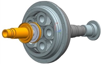
a)
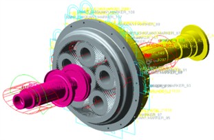
b)
According to the actual operation of the transmission system and various constraints of ADAMS, the solid model of the gearbox is processed as follows.
Fixed pairs are added between the input shaft and the sun gear, between the two inner gear rings, and at the 12 bolt holes between the gear rings and the output shaft respectively.
The bushings are added to the bearing positions of the input shaft, output shaft and five star gears respectively to simulate these bearings, The supporting stiffness of each bearing is provided by the cooperative enterprise, as shown in Table 2.
Table 2Support stiffness parameters of each bearing.
Bearing position | Leveling stiffness (N/m) | Axial stiffness (N/m) | Torsional stiffness (N/m) |
Input shaft support | 2.0×10⁷ | 2.0×10⁶ | 4.0×10³ |
Output shaft support | 1.2×10⁸ | 1.0×10⁷ | 1.8×10⁴ |
Planetary gear support | 2.0 ×10⁸ | 2.0×10⁷ | 4.0×10³ |
The Contact force based on Impact function is added between the sun gear and the star gear and between the star gear and the inner gear ring respectively. The contact stiffness of the contact pair between the sun gear and the star gear, the star gear and the inner gear ring is set to 1.0×10⁸ N·m, the damping coefficient is set to 0.1 % of the contact stiffness value, the nonlinear coefficient is set to 1.5, the cutting depth is set to 1.0×10⁻⁴ m, and the friction coefficient is defined as 0.02. Other parameters are adopted as default values. In summary, the simulation model of star transmission gear box as shown in Fig. 1(b) is established.
2.2. Multibody dynamic models screening
In order to balance the contradiction between simulation efficiency and simulation accuracy as far as possible, the Westgard decision diagram is introduced in this paper, and the "relative error distance method of speed, transmission ratio and meshing force" is used to screen various types of multi-body dynamic models in the process of building multi-body dynamic models of complex mechanical systems to carry out dynamic characteristic analysis. In order to ensure the accuracy of the analysis results, the rigid and flexible forms of the input shaft and the output shaft are the same when modeling, and the rigid and flexible forms of the outer and inner meshing contact pairs are the same. To sum up, the seven models shown in Table 3 are established. GSTIFF solver is used to simulate the models, provided that the simulation parameters and computer configuration are the same. The simulation time of each model is shown in Table 4.
Table 3Rigid and flexible matching model of gear box components
Model number | Input shaft | Sun wheel | Planetary gears | Inner gear ring | Output shaft |
1 | Rigid body | Rigid body | Rigid body | Rigid body | Rigid body |
2 | Rigid body | Rigid body | Flexible body | Rigid body | Rigid body |
3 | Flexible body | Rigid body | Rigid body | Rigid body | Flexible body |
4 | Rigid body | Flexible body | Rigid body | Flexible body | Rigid body |
5 | Flexible body | Rigid body | Flexible body | Rigid body | Flexible body |
6 | Rigid body | Flexible body | Flexible body | Flexible body | Rigid body |
7 | Flexible body | Flexible body | Flexible body | Flexible body | Flexible body |
When analyzing the dynamic response, scholars usually take the average value of each indicator signal in a period of time, and then compare the average value with the theoretical calculation value. This method is difficult to ensure that each indicator signal does not fluctuate significantly within a period of time, and it is difficult to ensure the accuracy and effectiveness of the analysis data. Westgard standard decision diagram [23]is one of the effective tools to determine the performance characteristics of a method. Therefore, it is introduced and “relative error distance method of speed, transmission ratio and meshing force” is used as evaluation criteria to screen various types of multibody dynamic models. The Westgard decision diagram divides each simulation signal into several samples, calculates the corresponding inaccuracy (Bias %) as the -axis and imprecision (CV %) as the -axis, and divides the entire Westgard decision diagram into four regions through three auxiliary reference lines. The four regions are non-conforming performance area, critical performance area, good performance area and excellent performance area.
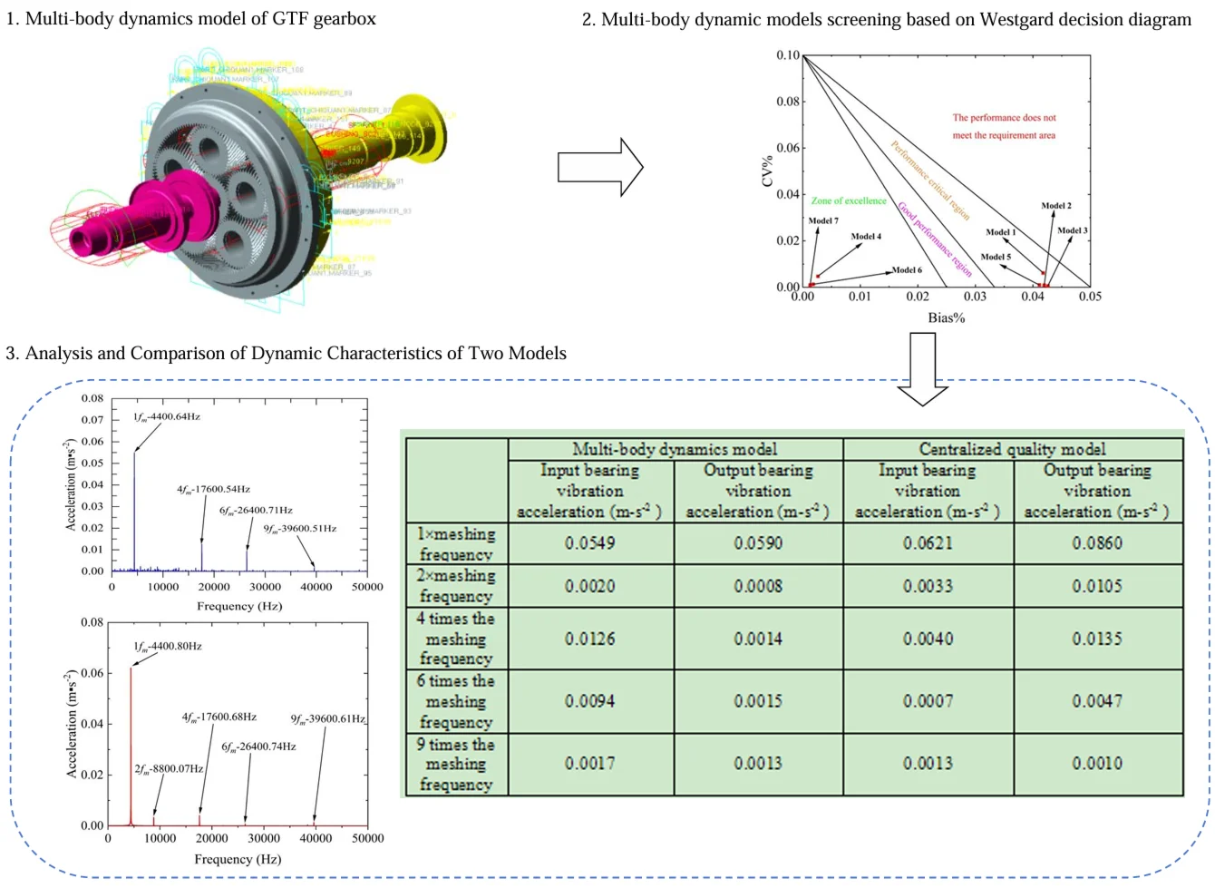
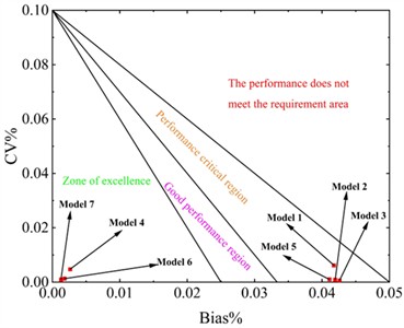
The simulation results of output speed, transmission ratio, internal and external meshing force are obtained for different multi-body dynamic models, and the inaccuracy and imprecision are calculated by taking 20 % of each of the five simulation indicators and marking them as the horizontal and vertical coordinates of data points on the method performance determination diagram shown in Fig. 2. The simulation performance of the models is judged according to the position of the points on the diagram. The closer the model data points are to the origin of the diagram, the higher the simulation accuracy will be.
As can be seen from Fig. 2, the simulation performance of the seven models is within the acceptable range, models 4, 6 and 7 are located in the excellent performance zone, models 1, 2, 3 and 5 are located in the critical performance zone, and model 7 is a multi-flexible model with the best simulation accuracy and effect, but the simulation time is the longest. By comparison, the simulation time of model 4 and 6 is shorter than that of the multi-flexible model. The main difference is whether the planetary gear in the gearbox is flexible. In the GTF gearbox model analyzed in this paper, the input and output shafts have low rotational speeds and small spans of shafts. Therefore, as shown in Model 4 of Table 3, the input, output shafts and planetary gears are set as rigid bodies, while the sun gear and inner gear rings are set as flexible bodies, which basically satisfy the simulation effect and have both simulation efficiency.
Table 4Simulation calculation time of gearbox model
Model number | Time consumption (s) | Model number | Time consumption (s) | Model number | Time consumption (s) |
1 | 371 | 4 | 34903 | 7 | 42955 |
2 | 17948 | 5 | 11745 | – | – |
3 | 507 | 6 | 35662 | – | – |
Fig. 2Westgard decision diagram of synthetic simulation performance of multiple multi-body dynamics models
2.3. Establishment of the concentrated parameter model
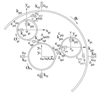
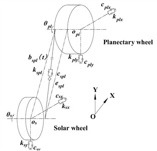
In this paper, the concentrated parameter method is used to construct the GTF star gear transmission system dynamics model shown in Fig. 3(a).
The sun gear and the planetary gear are connected by external meshing gear pair. Its dynamic model is shown in Fig. 3(b), and its dynamic equation can be expressed as follows:
For the sun gear, the equation is as follows [27]:
where: is the mass of the sun gear; , and are the support stiffness of the sun gear in the and directions, and are the support damping in the , direction of the sun gear; , , , , , and are the vibration displacement, velocity and acceleration of the nodes of the sun gear with concentrated parameter along the and directions respectively; , and are the meshing stiffness and meshing damping between the sun gear and the nth planetary gear respectively; is the tooth contact force between the sun gear and the nth planetary gear; is the rotational moment of inertia, and is the torsional vibration acceleration of the node where the sun gear concentrates the mass; is the torque on the sun gear; is the input moment.
Fig. 3a) Bending-torsional dynamics model of star gear transmission system, b) dynamic model of meshing between solar gear and nth planetary wheel, c) dynamic model of meshing between the nth planetary wheel and the inner gear ring
a)
b)
c)
For planetary gears, the equation is as follows [27]:
where: is the mass of the planetary gear; , and are the support stiffness of the planetary gear in the and directions, and are the support damping of the planetary gear in the and directions; , , , , , and are the vibration displacement, velocity and acceleration of the node with mass concentration of the planetary gear along the and directions respectively; and are the meshing stiffness and meshing damping between the nth planetary gear and the inner gear ring respectively; is the tooth contact force between the nth planetary gear and the inner gear ring; is the rotational moment of inertia, and is the torsional vibration acceleration of the node where the mass of the planetary gear is concentrated; is the torque on the planetary gear; is the pair torque of meshing between planetary gear and inner gear ring. is the angle between outer meshing plane and the -axis, in order to facilitate the calculation, make ; .
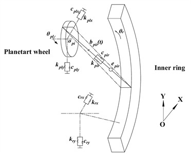
The motion pair between the planetary gear and the inner gear ring is the inner meshing gear pair, and its dynamics model is shown in Fig. 3(c).
For the inner gear ring, the equation is as follows [27]:
where: is the mass of the sun gear; , and are respectively the support stiffness of the inner gear ring in and directions, , and are respectively the support damping of the inner gear ring in the and directions; , , , , , and are respectively the vibration displacement, velocity and acceleration along the and direction of the node with mass concentration in the inner gear ring; is the moment of inertia, and is the torsional vibration acceleration of the node where the concentrated parameter in the inner gear ring; is the torque on the inner gear ring; is the output torque; is the radius of the base circle of the inner gear ring.
The average meshing stiffness of the helical gear pair is:
The meshing stiffness of gears presents a trend of periodic change with time. The meshing stiffness of the meshing pair of helical gears derived by Maatar [28] et al can be obtained as follows:
where:, the are respectively the time-varying meshing stiffness of the gear pair between the sun gear and the nth planetary gear, and between the nth planetary gear and the inner gear ring; , are respectively the average meshing stiffness corresponding to the outer and inner meshing pairs; , , and are the harmonic coefficients of each order of the outer and inner meshing pair respectively.
In gear transmission system, damping is mainly the meshing damping of gear meshing pairs. Currently, there is no accurate formula to calculate the value of damping, and the approximate value is usually calculated by empirical formula [29]:
where: is the meshing damping ratio, whose value ranges from 0.03-0.17, and it is 0.10 in this calculation; is the average meshing stiffness of the gear meshing pair; and is the mass of the driving gear and the driven gear.
3. Dynamic characteristics of GTF star transmission gearbox
3.1. Dynamic characteristics analysis of multibody dynamic model of the gearbox
According to the screening in 1.2, model 4 as shown in Fig. 4 is selected as the subsequent analysis model. The simulation conditions are shown in Table 5. The input speed and load are loaded in the form of STEP function, the loading time is 0.5s, the simulation time is 0.6 s, and the simulation step length is 0.00001.
Fig. 4Model 4
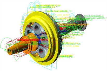
Table 5Simulation working conditions.
Importation speed (r/min) | RPM setting | Load torque (N∙m) | Load setting |
6000 | Step(time,0,0,0.5,1) *6000/60*360D | 557.025 | Step(time,0,0,0.5,1) *557.025 |
The simulation results of angular velocity of input shaft and output shaft, meshing force of the internal and external meshing pairs, and radial vibration acceleration at each bearing are shown in Fig. 5.
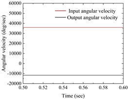
As can be seen from Fig. 5(a), the rotational speed of the input shaft is stable at 36000°/s, and the rotational speed of the output shaft is stable at about –11647.0554°/s, and the rotational speed of the input and output shafts is consistent with the theoretical value.
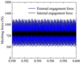
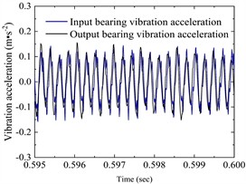
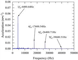
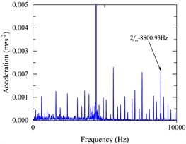
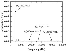
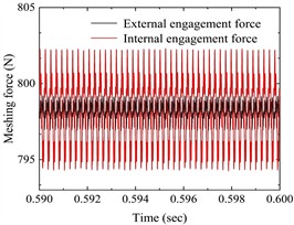
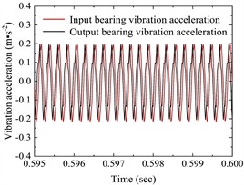
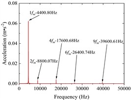
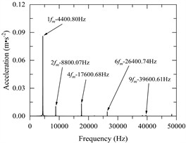
Fig. 5a) The angular velocity of the input and output axes, b) gear pair meshing force (local amplification), c) vibration acceleration changes of input-shaft bearing and output-shaft bearing (local amplification), d) vibration acceleration spectrum of input-shaft bearing, e) vibration acceleration spectrum of input-shaft bearing (local amplification), f) vibration acceleration spectrum of output-shaft bearing, g) vibration acceleration spectrum of output-shaft bearing (local amplification)
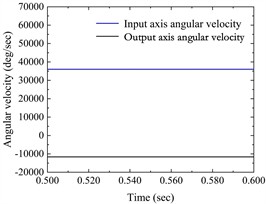
a)
b)
c)
d)
e)
f)
g)
As can be seen from Fig. 5(b), the meshing force of the outer meshing pair fluctuates up and down at 800.7533 N, with an absolute error of 2.5639 N compared with the theoretical value of 798.1894 N; the meshing force of the inner meshing pair fluctuates up and down at 797.5522 N, with an absolute error of 0.6372 N compared with the theoretical value of 798.1894 N. The meshing forces of the outer and inner meshing pairs are basically consistent with the theoretical values.
Fig. 5(c) shows the change of vibration acceleration of input-shaft bearing and output-shaft bearing; Fig. 5(d) and Fig. 5(e) show the vibration acceleration spectrum changes of the input-shaft bearing; Fig. 5(f) and Fig. 5(g) show the vibration acceleration spectrum changes of the output-shaft bearing. As can be seen from Fig. 5(c-g), the time domain peak value of radial vibration acceleration at the bearing of the input shaft is about 0.15 m·s-2, the main characteristic frequency domain is reflected in 1, 2, 4, 6, 9 times the snapping frequency, and the maximum peak value appears at 1 times the snapping frequency, with a peak value of 0.055 m·s-2. The time domain peak of radial vibration acceleration at the bearing of the output shaft is about 0.14 m·s-2, the main characteristic frequency domain is reflected in 1, 4, 6, 9 times the rodent frequency, and the maximum peak value also appears at 1 times the rodent frequency, the peak value is 0.059 m·s-2.
3.2. Dynamic characteristics analysis of concentrated parameter model of the gearbox
The dynamic equations of the gear transmission system established in 1.3 are numerically solved, the input speed is 6000 r /min, and the load torque is 557.025 N·m. Then the output speed, the meshing force of the outer and inner meshing pairs and the radial vibration acceleration at the bearing are shown in Fig. 6.
Fig. 6a) The angular velocity of the input shaft and output shaft, b) the meshing force of the gear pair (local amplification), c) vibration acceleration of the input-shaft bearing and the output-shaft bearing (local amplification), d) vibration acceleration spectrum of the input-shaft bearing, e) vibration acceleration spectrum of the output-shaft bearing
a)
b)
c)
d)
e)
As can be seen from Fig. 6(a), the rotational speed of the input shaft is stable at 36000°/s, and that of the output shaft is stable at about –11647.0550°/s, and the rotational speed of the input and output shafts is consistent with the theoretical value.
As can be seen from Fig. 6(b), the meshing force of the outer meshing pair fluctuates up and down at 798.1762 N, with an absolute error of 0.0132 N from the theoretical value of 798.1894 N; the meshing force of the inner meshing pair fluctuates up and down at 798.1764 N, with an absolute error of 0.013 N from the theoretical value of 798.1894 N. The meshing forces of the outer and inner meshing pairs are in good agreement with the theoretical values.
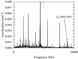
Fig. 6(c) shows the change of vibration acceleration of input-shaft bearing and output shaft bearing; Fig. 6(d) shows the change of vibration acceleration spectrum of the input shaft bearing. Fig. 6(e) shows the change of vibration acceleration spectrum of the output shaft bearing. As can be seen from Fig. 6(c-e), the time domain peak of radial vibration acceleration at the bearing of the input shaft is about 0.23 m·s-2, the main characteristic frequency domain is reflected in 1, 2, 4, 6, 9 times the rodent frequency, and the maximum peak appears at 1 times the rodent frequency, with a peak value of 0.062 m·s-2. The time domain peak of radial vibration acceleration at the bearing of the output shaft is about 0.24 m·s-2, the main characteristic frequency domain is reflected in 1, 2, 4, 6, 9 times the snapping frequency, and the maximum peak value also appears at 1 times the snapping frequency, the peak value is 0.086 m·s-2.
4. Comparison of dynamic characteristics
4.1. Analysis of time domain results of each index
The time domain results of each index of the gearbox centralized mass model and the multibody dynamic model are shown in Table 6.
Table 6Time-domain simulation results of each index of the two models
Theoretical value | Multi-body dynamics model | Centralized mass model | |
Input speed (deg/sec) | 36000 | 36000 | 36000 |
Output speed (deg/sec) | –11647.0554 | –11647.0554 | –11647.0550 |
The meshing force of the outer meshing pair(N) | 798.1894 | 800.7533 | 798.1762 |
The meshing force of the inner meshing pair (N) | 798.1894 | 797.5522 | 798.1764 |
Input Bearing vibration acceleration at (m-s-2) | – | 0.15 | 0.23 |
Output bearing vibration acceleration at (m-s-2) | – | 0.14 | 0.24 |
As can be seen from Table 6, according to the index of rotational speed, the two models agree well with each other and with the theoretical value. According to the index of meshing force, there is a good agreement between the two models and between the two models and the theoretical value. The maximum absolute error of meshing force between the two models is 2.5771 N. From the time-domain index of radial vibration acceleration, the absolute error of vibration acceleration at the bearing of the input shaft and the absolute error of vibration acceleration at the bearing of the output shaft are 0.08 m·s-2 and 0.1 m·s-2 respectively.
4.2. Analysis of frequency-domain results of vibration acceleration
The frequency-domain results of radial vibration acceleration of the gearbox concentrated parameter model and the multi-body dynamic model are shown in Table 7.
Table 7Frequency-domain simulation results of radial vibration acceleration of two models.
Multi-body dynamics model | Centralized quality model | |||
Input bearing vibration acceleration (m-s-2) | Output bearing vibration acceleration (m-s-2) | Input bearing vibration acceleration (m-s-2) | Output bearing vibration acceleration (m-s-2) | |
1×meshing frequency | 0.0549 | 0.0590 | 0.0621 | 0.0860 |
2×meshing frequency | 0.0020 | 0.0008 | 0.0033 | 0.0105 |
4 times the meshing frequency | 0.0126 | 0.0014 | 0.0040 | 0.0135 |
6 times the meshing frequency | 0.0094 | 0.0015 | 0.0007 | 0.0047 |
9 times the meshing frequency | 0.0017 | 0.0013 | 0.0013 | 0.0010 |
According to the frequency-domain index of radial vibration acceleration, the main characteristic frequencies of radial vibration acceleration at the bearing of the input shaft of the gearbox multi-body dynamic model are 1, 2, 4, 6 and 9 times the snapping frequency, and the maximum peak value is 0.0549 m·s-2 at the doubling of the snapping frequency. The main characteristic frequencies of radial vibration acceleration at the bearing of the output shaft are 1, 4, 6, and 9 times the snapping frequency, and the maximum peak value is 0.0590 m·s-2 at 1 times the snapping frequency, and the value is smaller at 2 times the snapping frequency. The main characteristic frequency domains at the bearing of the input shaft and the output shaft of the lumped mass model are 1, 2, 4, 6 and 9 times the snapping frequency. The maximum peak value at the bearing of the input shaft is 0.0621 m·s-2 at 1 times the snapping frequency, and the maximum peak value at the bearing of the output shaft is 0.0860 m·s-2 at 1 times the snapping frequency.
5. Conclusions
In this paper, the Westgard decision diagram is introduced, and various multi-body dynamics models of GTF star gearboxes are screened out based on the “relative error distance method of speed, transmission ratio and meshing force”, and a simulation model that takes into account of the analysis efficiency and accuracy is obtained, which overcomes the limitation of the evaluation of a single simulation index. Through the simulation analysis of the multi-body dynamics model and the centralised mass model of the gearbox, the dynamic characteristics of the system, such as output speed, meshing force and bearing vibration acceleration, are extracted. The comparison results show that the results of the two models have good consistency under the same working conditions and parameter settings, indicating that both methods can be used for the study of the dynamic characteristics of gear transmission systems.
Both the multi-body dynamics model and the concentrated parameter model can better analyse the meshing force of the gear pair, which agrees with the theoretical calculated values. As the multi-body dynamics model takes into account the effects of vibration and impact, a smaller axial force is generated, resulting in a slightly larger value of the meshing force; whereas the centralised mass model and the theoretical calculation are based on a two-dimensional planar vibration system, with zero axial force, so that the two values of the meshing force are consistent.
The study shows that the simulation results of the rigid-flexible coupled multibody dynamics model screened by the Westgard decision diagram are consistent with the centralised parameter model and the theoretical values, which verifies the feasibility and effectiveness of the method. The Westgard decision diagram can be used to quickly screen the multi-body dynamic model with both simulation accuracy and efficiency, which provides a theoretical basis for the analysis of the dynamic characteristics of complex mechanical systems, and improves the correctness and engineering practicability of the simulation analysis.
References
-
T. C. Ouyang, H. Z. Huang, and P. Wang, “Dynamic modeling and optimization design of offset printing machine gear transmission system,” Journal of Southeast University: Natural Science Edition, Vol. 46, No. 6, pp. 1172–1178, 2016.
-
K. Chen, Y. Huangfu, Z. Zhao, H. Ma, and X. Dong, “Dynamic modeling of the gear-rotor systems with spatial propagation crack and complicated foundation structure,” Mechanism and Machine Theory, Vol. 172, p. 104827, Jun. 2022, https://doi.org/10.1016/j.mechmachtheory.2022.104827
-
J. Liu, X. Li, R. Pang, and M. Xia, “Dynamic modeling and vibration analysis of a flexible gear transmission system,” Mechanical Systems and Signal Processing, Vol. 197, p. 110367, Aug. 2023, https://doi.org/10.1016/j.ymssp.2023.110367
-
T. Jianjun et al., “Dynamic modeling and analysis of planetary gear train system considering structural flexibility and dynamic multi-teeth mesh process,” Mechanism and Machine Theory, Vol. 186, p. 105348, Aug. 2023, https://doi.org/10.1016/j.mechmachtheory.2023.105348
-
S. Portron, P. Velex, and V. Abousleiman, “A hybrid model to study the effect of tooth lead modifications on the dynamic behavior of double helical planetary gears,” Proceedings of the Institution of Mechanical Engineers, Part C: Journal of Mechanical Engineering Science, Vol. 233, No. 21-22, pp. 7224–7235, May 2019, https://doi.org/10.1177/0954406219846156
-
D. D. Wu, Z. Liu, and H. W. Zhao, “Finite element analysis of factors influencing dynamic meshing characteristics of spiral bevel gear pairs,” Journal of Guilin University of Aerospace Technology, Vol. 29, No. 3, pp. 313–319, 2024.
-
X. P. Ran, “Finite element analysis of meshing characteristics and ease-off topology modification design for spiral bevel gears,” Southwest Jiaotong University, 2022.
-
X. N. Cai, “Dynamic simulation of straight-toothed cylindrical gears based on ADAMS,” Coal Mine Machinery, Vol. 40, No. 9, pp. 184–186, 2019, https://doi.org/10.13436/j.mkjx.201909060
-
Y. L. Cheng, Z. M. Xiao, and X. Wang, “Dynamic characterization and ADAMS simulation study of straight-toothed cylindrical gears,” Mechanical Strength, Vol. 38, No. 4, pp. 667–674, 2016, https://doi.org/10.16579/j.issn.1001.9669.2016.04.001
-
J. Zhang and X. Z. Liu, “Modeling and analysis of multi-body dynamics of helical tooth planetary drive,” Vibration and Shock, Vol. 33, No. 7, pp. 11–17, 2014, https://doi.org/10.13465/j.cnki.jvs.2014.07.003
-
J. Yu, S. Wang, L. Wang, and Y. Sun, “Gearbox fault diagnosis based on a fusion model of virtual physical model and data-driven method,” Mechanical Systems and Signal Processing, Vol. 188, p. 109980, Apr. 2023, https://doi.org/10.1016/j.ymssp.2022.109980
-
D. Zhu, Z. Li, and N. Hu, “Multi-body dynamics modeling and analysis of planetary gearbox combination failure based on digital twin,” Applied Sciences, Vol. 12, No. 23, p. 12290, Dec. 2022, https://doi.org/10.3390/app122312290
-
X. D. Wu, “Noise analysis and optimization research of wheel loader transmission,” Qingdao University of Science and Technology, 2023.
-
W. Yan, “Research on vibration characteristics of a two-stage herringbone gear transmission system with crack-pitting coupling,” Xi’an Technological University, 2024.
-
Z. Zhang et al., “Research on rigid-flexible coupling modeling and load characteristics of gear transmission systems,” Journal of Mechanical Strength, Vol. 42, No. 1, pp. 239–245, 2020, https://doi.org/10.16579/j.issn.1001.9669.2020.01.037
-
Z. H. et al., “Rigid-flexible coupling modeling and fault characteristic simulation research of planetary gear transmission systems,” Journal of Mechanical Transmission, Vol. 45, No. 3, pp. 46–51, 2021, https://doi.org/10.16578/j.issn.1004.2539.2021.03.008
-
W. L. Wang et al., “Research on vibration and noise reduction of planetary gear reducers based on rigid-flexible coupling,” Modern Manufacturing Engineering, No. 2, pp. 79–85, 2022, https://doi.org/10.16731/j.cnki.1671-3133.2022.02.012
-
F. Jiang, K. Ding, S. Zhang, Z. Wu, and G. He, “Vibration response mechanism of fixed-shaft gear train with cracks based on rigid-flexible coupling dynamics and signal convolution model,” Mechanical Systems and Signal Processing, Vol. 198, p. 110417, Sep. 2023, https://doi.org/10.1016/j.ymssp.2023.110417
-
J. C. Li, C. Y. Fang, and H. J. Que, “Dynamic modeling and vibration characteristics study of herringbone gear transmission system,” Journal of Mechanical and Electrical Engineering, pp. 1–11, 2025.
-
Y. Pan, “Research on flexible multibody dynamics of double involute gears considering the influence of tooth surface pitting,” Qingdao University of Science and Technology, 2023.
-
G. X. Fu, F. R. Guo, and W. D. Long, “Application of Westgard method to evaluate the acceptability of decision diagram judgment assays,” International Journal of Laboratory Medicine, Vol. 34, No. 16, pp. 2152–2154, 2013.
-
W. J. Fu, L. F. Peng, and L. Liu, “Evaluation of Westgard’s standardized decision diagram on the performance of clinical biochemical testing systems,” Laboratory Medicine and Clinics, Vol. 8, No. 5, pp. 541–542, 2011.
-
J. M. Zeng, Y. F. Long, and M. O. Li, “Application of the Westgard method to evaluate decision diagrams to determine the performance of the Sysmex XE5000 whole blood cell analyzer,” Experimental and Laboratory Medicine, Vol. 30, No. 3, pp. 225–227, 2012.
-
D. M. Wen, X. M. Zhang, and W. J. Wang, “Application of Westgard method decision diagram in analyzing performance evaluation of testing system,” Experimental and Laboratory Medicine, Vol. 28, No. 3, pp. 205–208, 2010.
-
J. Huang, P. Wan, and C. Liu, “Modeling and model validation of rigid-flexible coupled planetary gearboxes,” Mechanical Engineering and Automation, Vol. 3, No. 3, pp. 69–71, 2019.
-
H. Zhang, H. Zheng, and X. P. Li, “Simulation analysis of GTF engine gear train dynamics,” Mechanical Design and Manufacturing, Vol. 1, No. 1, pp. 146–149, 2019, https://doi.org/10.19356/j.cnki.1001-3997.2019.01.038
-
M. H. Yin, “Dynamic characteristics of herringbone gear-rotor-journal bearing system considering lubrication effect,” Northwestern Polytechnical University, 2017.
-
M. Maatar and P. Velex, “An analytical expression for the time-varying contact length in perfect cylindrical gears: some possible applications in gear dynamics,” Journal of Mechanical Design, Vol. 118, No. 4, pp. 586–589, Dec. 1996, https://doi.org/10.1115/1.2826933
-
H. Liu, “Dynamic characterization of GTF aero-engine star gear transmission system,” Xi’an University of Technology, 2021.
About this article

The authors are grateful for financial support from the research foundation of the Education Department of Liaoning Province (No. JYTMS20230213) and the Project of Civil Aircraft Specialized Research (No. MJ2018-D-20).
The datasets generated during and/or analyzed during the current study are available from the corresponding author on reasonable request.
Xiaomei You: conceptualization, supervision, writing-original draft preparation, writing-review and editing. Haonan Yang: data curation, investigation, methodology, software, writing-original draft preparation. Yu Cui: validation, writing-review and editing. Haixu Wang: resources, supervision.
The authors declare that they have no conflict of interest.
