Abstract
The dynamic characteristic of the timing system has a significant impact on the performance of the engine's NVH. With low contact stress and strong anti-interference ability, the arc tooth synchronous belt was adopted by engine timing transmission system. The multi-body dynamics model of the in-line four cylinder engine timing system was established. We explored the influence of crankshaft speed and initial tension on the dynamic performance of the engine timing system. The result shows when the crankshaft speed 2000 r/min and the initial tension of the synchronous belt 300 N, the load distribution of the RU type synchronous belt teeth root is more uniform. The stress is 0.2474 N/mm2 lower than the average value, and the transverse vibration amplitude decreases by 0.3067 mm. Under this circumstance, the fluctuation amplitude of camshaft angular velocity is 6.5312 rad/s lower than the maximum average amplitude, so the transmission error is reduced by 37.95 %. The fluctuation amplitude of interference value decreases by 0.3413 mm, and the fluctuation amplitude of interference velocity decreases by 263.8908 mm/s. The synchronous belt based engine timing transmission is more stable and the dynamic performance is better. It laid a solid foundation for the optimization of the tooth profile and load conditions of the engine timing system.
Highlights
- The contact stress is concentrated in the belt tooth root during the timing belt meshing transmission.
- The maximum transverse vibration fluctuation occurs on the slack side partition of the synchronous belt.
- The belt tooth slip rate and the tension difference between the belt’s slack and tight could induce transmission error.
1. Introduction
Timing system is an important part of engine valve train and it’s dynamics characteristic influence the NVH (Noise, Vibration and Harshness) of the engine. With high working efficiency, strong wear resistance and light weight, the synchronous belt is widely applied in the engine timing system for energy saving and carbon emission reduction. Compared with chain drive and gear drive, the synchronous belt is more suitable for timing systems with complex transmission forms [1]. The structure of the timing belt transmission system includes front-end accessories, such as timing belt, crankshaft pulley, intake and exhaust camshaft pulley and tensioner. According to the tooth profile, the synchronous belt is mainly divided into trapezoidal tooth and arc tooth. The polygon-like effect always occurs when the synchronous belt is engaging into and out of the pulley due to their material properties discrepancy. Through connecting multiple arc curves, the arc tooth profile can approach the pulley smoothly and reduce the negative impact caused by polygon-like effect. Additionally, the stress performance and anti-interference ability of circular arc tooth synchronous belt are also better than trapezoidal tooth synchronous belt.
In the early days, many scholars have focused on the load distribution of the synchronous belt teeth. Gerbert et al. established for the first time the theory for analyzing belt tension and tooth load distribution with the spring model considering different load conditions, and the replication experiment was conducted to investigate the belt characteristics under different load conditions [2-3]. Since the Millennium, Kagotani M et al. experimentally studied the effect of initial tension on the transmission error of synchronous belt under quasi-static condition [4-6]. Takagishi H. et al. calculated belt drive simulation data based on multi-body dynamics software to predict the maximum load and vibration level when the pulley is conjugated with the belt [7]. Wang F. et al. considered geometric nonlinearity and boundary condition nonlinearity, analyzed the influence of arc tooth synchronous belt acceleration on transmission accuracy by finite element method [8, 9]. Guo J. H’s analyzed the belt tooth stress distribution and the generation mechanism of belt vibration and noise when the synchronous belt transmission system was subjected to external excitation, and then optimized the structural parameters of the belt and pulley’s profiles [10-12]. Yang G. et al. studied deeply the vibration of belt drive system by using multi-body dynamics analysis method [13, 14]. Recently, synchrouns belt has been adopted in the non-circular pulley drive system. Passos S et al. adopted the numerical simulation and experiment to verify the elliptical pulley transmission system can reduce the belt tension and transmission error under a specific initial phase angle [15]. Combined data mining technology and multilayer perceptron neural network, Khazaee M. et al. presented an intelligent method based on vibration to predict the remaining service life of synchronous belt [16]. Sequenzia G. et al. numerically and experimentally investigated the dynamic characteristics of water pump drive in high-performance internal combustion engine [17]. Previous scholars mostly conducted theoretical analysis on the simple model of synchronous belt transmission, while the dynamic performance of the timing system is vital. Herein, we establishes the multi-body dynamics model of the in-line four-cylinder engine timing system, and analyzed the influence of external load on the dynamic performance of the system to improve the working efficiency and prolong the lifespan of the timing system. It provides theoretical basis for multi-body dynamics analysis of timing system.
2. Timing system model establishment
2.1. Establishment of mathematical model for dynamic characteristics of timing system
The power source of the timing system is the superposition of harmonic excitation generated by crankshaft speed and torsional vibration, and the motion equation [18, 19] is:
where, is the average speed of crankshaft, is the fluctuation amplitude of the -th order angular velocity, is the -th order angular velocity fluctuation phase.
By defining that there are 1 tensioner and fixed axis pulleys in the system, the differential equation of motion of the system can be obtained:
where is the number of the tensioner in the timing system.
Define the state quantity as:
where is the angular displacement and is the excitation angular velocity.
Reduce the order of Eq. (2) to obtain the first-order differential equations:
The angular displacement and angular velocity of each pulley can be obtained by using the above formula. The timing belt will produce nonlinear length change in the working process, resulting in fluctuating belt tension. The variation of belt length is divided into arc segment variation and belt section variation , as follows:
where, Is the direction angle of pulley torsion, Is the wrap angle of the belt on the pulley, is the pulley radius, is the length of the belt section of the corresponding pulley, and is the creep of synchronous belt on pulley and the change of belt length in meshing area.
Then, the tension fluctuation value is obtained through the change of belt length, as follows:
where, is the belt length change caused by the swing of the tensioning arm of the automatic tensioner.
2.2. Establishment of rigid flexible coupling dynamic model
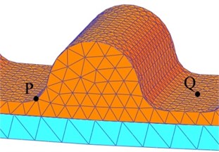
The structure and parameters of the normal surface of the RU timing belt teeth are shown in Fig. 1 and Table 1.
Fig. 1Schematic diagram of normal tooth profile
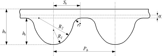
Table 1Definition of dimension parameters. Unit (mm)
Name | Codename | Size |
Tooth pitch | 9.525 | |
Belt high | 5.4 | |
Pitch difference | 0.686 | |
Fillet radius of teeth root | 1.25 | |
Tooth height | 3.44 | |
Tooth radius | 2.33 | |
4.30 | ||
Half width of teeth root | 3.81 |
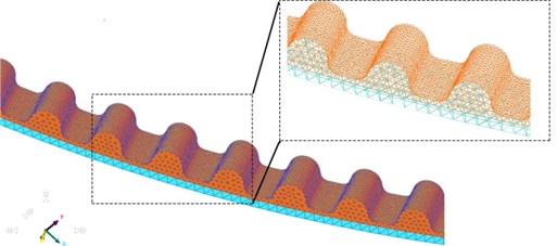
The timing belt is composed of belt back layer, strength layer, nylon cloth layer and belt teeth [20]. The material property parameters are listed in Table 2. The synchronous belt meshing adopts flexible body layered division technology was depicted in Fig. 2.
Table 2Material properties of each layer of timing belt
Neoprene | Glass fiber | Nylon cloth | |
Density (×103 kg/m3) | 1.27 | 2.6 | 1.15 |
Young’s modulus (MPa) | 0.045 | 0.094 | 0.042 |
Poisson coefficient | 0.46 | 0.4 | 0.43 |
Fig. 2Multi-layer mesh generation method
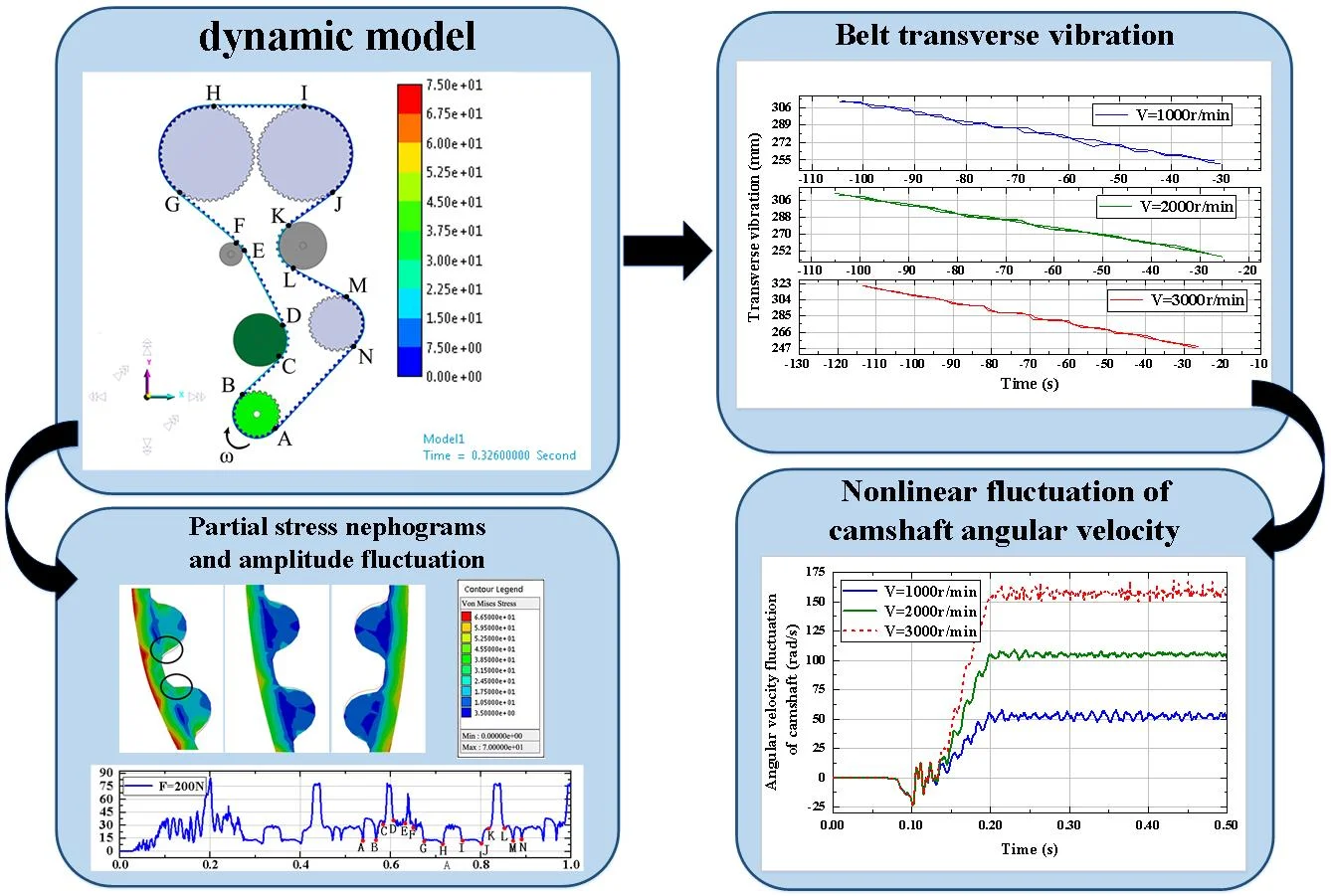
The virtual prototype mainly included crankshaft pulley, tensioner, idler, intake camshaft pulley, exhaust camshaft pulley, water pump pulley and timing belt. The layout parameters are listed in Table 3. The initial belt tension is defined as 300 N, the crankshaft speed is 1000 r/min, and an initial load torque 4500 N·mm was applied on the camshaft. The contact method of pulley and timing belt is defined as geometry contact. We define the displacement in Z, RX and RY directions are zero, meanly, there is no movement along the axis. The tooth surface contact area of the pulley is locally refined, and the number of grid elements is 67801. The rigid-flexible coupling dynamics model was illustrated in Fig. 3.
The direction of crankshaft rotation is defined as depicted in Fig. 3. We set each meshing point as points A-N in clockwise order, as shown in Fig. 3. The belt tooth will be squeezed when conjugated with the tooth groove of the pulley during the meshing process. The bending stress generated during meshing will easily cause the concentration of the stress. Therefore, we herein choose the node P and the tooth groove node for analysis the stress variation during the meshing, as shown in Fig. 4. The simulation time is set as 0.5 s, the number of steps 500.
Table 3Parameters of system layout
Part name | Number of teeth | diameter | coordinate | coordinate | coordinate |
Crankshaft pulley | 24 | 72.7656 | 0 | 0 | 0 |
Water pump pulley | 28 | 84.8932 | 120.093 | 127.142 | 0 |
Guide idler 1 | 74.548 | 70 | 244.991 | 0 | |
Exhaust camshaft pulley | 48 | 145.531 | 72.149 | 383.49 | 0 |
Intake camshaft pulley | 48 | 145.531 | –75.228 | 383.49 | 0 |
Guide idler 2 | 37.548 | –39.031 | 232.1 | 0 | |
Tensioner | 82.548 | 4.452 | 1.2.61 | 0 |
3. The influence of crankshaft speed on system dynamics
In the process of synchronous belt meshing transmission, the speed of crankshaft pulley affected the belt tooth stress and system dynamics. Therefore, under the condition of initial belt tension 300 N, the crankshaft speed 1000 r/min, 2000 r/min, and 3000 r/min are selected to analyze the stress distribution of the timing belt and the influence of system dynamics performance under different crankshaft speeds.
Fig. 3Multi body dynamic model of timing system
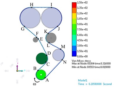
Fig. 4Selection of analysis nodes
3.1. Influence of belt tooth stress
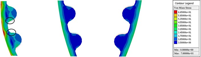
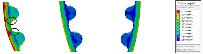
The stress variation of synchronous belt under different crankshaft speeds is shown in Fig. 5. The results show that the maximum stress of the root node of pulley is 78.1912 N/mm2, 80.0772 N/mm2 and 80.4374 N/mm2 with the increase of crankshaft speed, respectively. And the tooth stress enhances with the increment of the crankshaft speed. The position of maximum stress is always in the meshing process of the timing belt and the crankshaft pulley, as depicted in the Fig. 5.
Fig. 5Stress cloud of synchronous belt in contact with each pulley
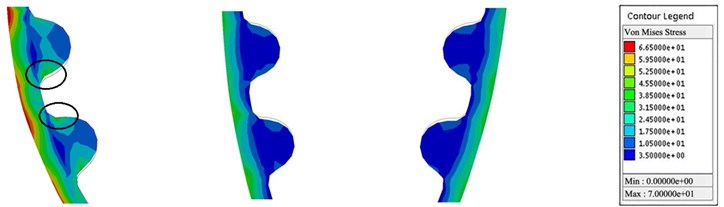
a) Belt AB, GH and IJ (1000 r/min)
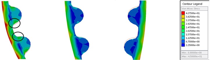
b) Belt AB, GH and IJ (2000 r/min)
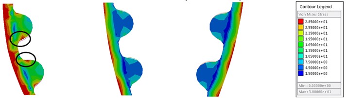
c) Belt AB, GH and IJ (3000 r/min)
To alleviate the transmission failure caused by the stress vibration, the tensioner is applied to adjust the belt tension by pressing the timing belt inward during the operation. Therefore, the bending stress on the back of the AB belt section of the timing belt is lower than that of the GH and IJ belt sections. Simultaneously, the crankshaft is utilized as the output power source, and the load of the camshaft is offset by the meshing transmission of the timing belt, therefore the stress of the AB belt section will be higher.
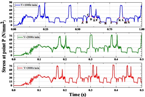
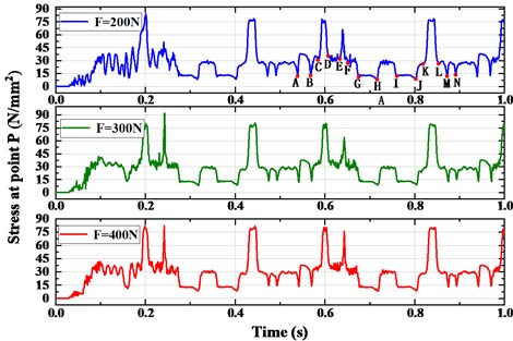
Fig. 6 shows the stress variation at node P under different velocities. Taking the stress fluctuation curve of crankshaft speed 1000 r/min as the analysis object, the points A-N in the figure are the meshing points in Fig. 3 0.00 s-0.16 s system is in the loading phase. It can be seen from the figure that the stress amplitude of the CD and KL belt sections is larger. The guide idler 1 and the tensioner simultaneously rely on inward compression of the timing belt to maintain the tension of the belt during the operation of the timing system, so the tooth root of the belt is subjected to greater bending stress. The stress value of D-G belt section fluctuates greatly. The reason for that is the lower the speed, the greater the amplitude of its transverse vibration when the timing belt is coming to contact with the guide idler 2. When the belt back hits the guide idler at high frequency, the bending stress becomes higher and the amplitude fluctuates violently. Therefore, when the crankshaft speed 1000 r/min, the stress value of the node in the EF belt section reaches to the maximum value of 90.9346 N/mm2. Simultaneously, the stress value of the AB belt section is greater than that of the GH and IJ belt sections, which conform to the results of stress cloud diagram illustrated the above.
Fig. 6Periodic fluctuation curve of stress at node P
3.2. Influence of transverse vibration
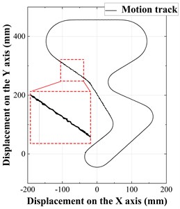
The trajectory of the synchronous belt is depicted in Fig. 7(a). The definition method of the meshing start point and meshing end point of each pulley and timing belt is the same as Fig. 3. It can be seen from the figure that in each belt section, the transverse vibration of the D-G belt section is more obvious, and the amplitude of FG belt section is larger. It can be accountable that the crankshaft rotates to offset the camshaft load during the operation of the timing system, causing the camshaft to produce angular velocity fluctuations and resulting in transverse vibration. In addition, the D-G belt section is longer and the radius of the guide idler 2 is much smaller, in hence, the transverse vibration amplitude would be much larger.
Fig. 7(b) shows the transverse vibration amplitude of FG band at different crankshaft velocities. When the crankshaft speed 2000 r/min, the maximum vibration amplitude is 1.014 mm. However, the torque of driven camshaft is not big enough to offset the fluctuation of load torque when the crankshaft speed is reduced to 1000 r/min, resulting in higher transverse vibration of synchronous belt and the maximum vibration amplitude can reach up to 1.748 mm. The meshing frequency of the synchronous belt increases gradually with the increasing crankshaft speed, and so will the belt tension fluctuation increase, which will arise the increase of the transverse vibration. Through the simulation we can obtain the maximum vibration is 1.659 mm when 3000 r/min.
Fig. 7The selection of the analyzed belt segment and the nonlinear amplitude fluctuation of transverse vibration
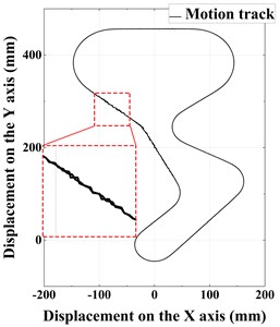
a) Motion track
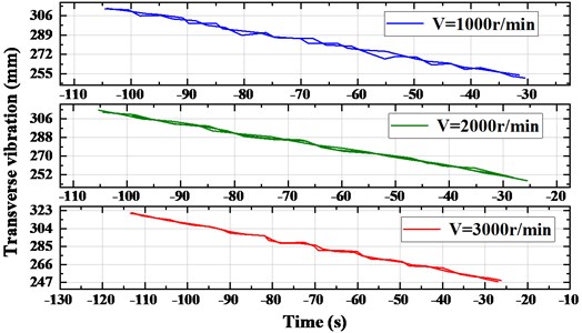
b) Amplitude fluctuation
3.3. Influence of transmission error
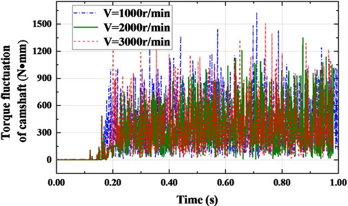
Affected by the transverse and longitudinal vibrations simultaneously, the intake and exhaust camshafts produce angular velocity fluctuations and torque fluctuations, which will generate transmission errors in the timing system. Meanwhile, the belt transverse vibration law is positively correlated with the camshaft angular velocity fluctuation. That means the greater the fluctuation amplitude, the greater the transmission error. Fig. 8 shows the camshaft’s angular velocity fluctuation under different crankshaft speeds.
Fig. 8Nonlinear fluctuation of camshaft angular velocity
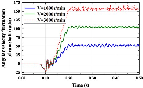
The results show that when the crankshaft speed is too small or large, the fluctuation amplitude of camshaft angular velocity will be large, and it is positively correlated with the law of transverse vibration. When the crankshaft speed 2000 r/min, the camshaft angular velocity fluctuates slightly, and its maximum fluctuation amplitude is 1.315 rad/s. When the crankshaft speed 3000 r/min, the angular velocity of the camshaft fluctuates greatly, and the maximum fluctuation amplitude is 12.526 rad/s. If the crankshaft speed is too small, the torque produced by velocity fluctuation cannot offset the camshaft load, which will cause large angular velocity fluctuations. As the crankshaft speed increases, the belt tension fluctuation becomes larger and larger. With the camshaft angular velocity fluctuation increases, the timing belt resists the camshaft load. Therefore, when the crankshaft speed 3000 r/min, the amplitude of the camshaft angular velocity fluctuation is greater than the crankshaft speed 1000 r/min.
Fig. 9 shows the camshaft torque fluctuation curve at different crankshaft speeds during the meshing transmission process. From the figure, when the crankshaft speed 1000 r/min, because the speed is small, the torque provided can only offset a part of the camshaft load moment. The large fluctuations is occurred in the camshaft torque during the meshing transmission process, with a peak value of 1703.465 N·mm. When the crankshaft speed 3000 r/min, the belt tension fluctuates greatly, and the transverse and longitudinal vibration of the synchronous belt is large. As a result, the angular velocity of the camshaft fluctuates greatly, and the peak value reaches 1495.822 N·mm. When crankshaft speed 2000 r/min, the amplitude of camshaft torque fluctuation is small, peak value 1348.610 N·mm.
Fig. 9Nonlinear fluctuation of camshaft torque amplitude
3.4. Influence of interference fluctuation
The transmission between the synchronous belts and pulleys will produce boundary interference. The simulation indicates that the greater the contact stress, the bigger interference. Fig. 10 shows the interference relationship between the timing belt and each pulley under different crankshaft speeds. The results show that the fluctuation amplitude of the interference increases as the crankshaft speed rises. When the crankshaft speed 1000 r/min, the interference fluctuates slightly, and the maximum fluctuation amplitude is 0.128 mm. While the interference fluctuates sharply and the maximum fluctuation amplitude reach up to 0.375 mm when the crankshaft speed 3000 r/min. The crankshaft counteracts the fluctuation of camshaft load torque by relying on the tension difference between the slack belt and tight belt. In this process, the higher the rotation speed of the pulley, the higher the meshing frequency between the synchronous belt and the pulley. Meanwhile, with the increment of the contact stress between the crankshaft pulley and the timing belt, the interference augments sharply.
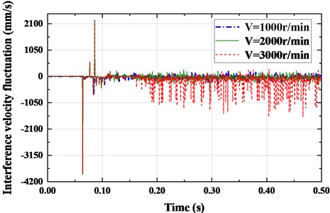
The interference speed fluctuation of the timing belt and pulley under different crankshaft speeds is also discussed. It can be seen from Fig. 11 that the higher the vibration frequency, the more severely the interference velocity fluctuation. And the interference velocity fluctuation and the interference fluctuation are positively correlated. The interference speed fluctuation is small and the maximum fluctuation amplitude is 540.796 mm/s when the crankshaft speed 1000 r/min. That is because when the crankshaft speed is small, the contact stress between the belt and the pulley is small and so is the fluctuation of the interference. Under the same circumstance, the interference speed fluctuates greatly and the maximum fluctuation amplitude is 1573.905 mm/s when 3000 r/min. It can be accountable that the belt tension fluctuation becomes larger when the crankshaft speed is relatively high. The contact stress between the belt and the pulley becomes larger, and the interference fluctuates, resulting in the higher interference velocity fluctuation amplitude.
Nevertheless, interference fluctuation and stress are small When crankshaft speed 1000 r/min, the transverse vibration and transmission error are large. The large vibration will shorten the lifespan of the timing belt, and even affect the stability of the timing system. Therefore, when the crankshaft speed 2000 r/min, the dynamic performance of the timing system is better.
Fig. 10Nonlinear variation curve of interference depth
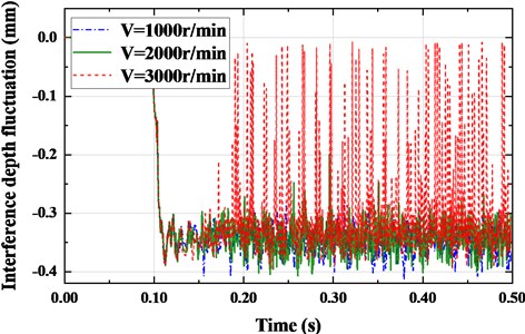
Fig. 11Nonlinear fluctuation law of interference velocity
4. The influence of initial tension of synchronous belt on system dynamics
The synchronous belt is the only flexible element in the timing system. Its initial tension affects the stress distribution of belt teeth, and the vibration characteristics of synchronous belt, and the transmission error of the system. The phenomenon of tooth skipping or even tooth disengagement appears when the initial tension is too small. On the contrary, the stress concentration occurs as the initial tension is too large, which would shorten the lifespan the synchronous belt and the service time of the timing system. Therefore, we discuss the effect of initial tension of 200 N, 300 N and 400 N under the condition of initial crankshaft speed 1000 r/min on the synchronous belt as follow.
4.1. Influence of belt tooth stress
Under the constant external load, the stress cloud of synchronous belt meshing with different pulleys is shown in Fig. 12. From left to right, there are crankshaft pulley meshing section, inlet camshaft meshing section and exhaust camshaft meshing section. The results show that with the increase of initial tension, the maximum stress of tooth root node is 79.4376 N/mm2, 78.7592 N/mm2 and 81.091 N/mm2 respectively. And the position of maximum stress is marked. As the initial tension increases, the initial tensile stress generated on the reinforcing layer of the synchronous belt aggravate. It causes the stress at the back of the belt increases. Additionally, the greater the initial tension, the greater the contact stress between the belt and the pulley, making the increment of the stress value of the tooth node. When the initial tension is small, the synchronous belt and the pulley are not closely meshed. And then the fluctuation of camshaft load torque will cause the transverse and longitudinal vibration of the synchronous belt, resulting in the high impact frequency between the belt teeth and the cogging of the pulley. The phenomenon of large stress value occurs in the process of high-frequency impact. Therefore, the maximum stress at the node when the initial tension 200 N is greater than that 300 N.
Fig. 12Stress cloud of synchronous belt in contact with each pulley
a) Belt AB, GH and IJ (200 N)
b) Belt AB, GH and IJ (300 N)
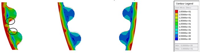
c) Belt AB, GH and IJ (400 N)
Fig. 13 is the stress variation of node P when the synchronous belt was engaging with the pulley. It can be seen from the figure that the stress fluctuation amplitude of CD section and KL section is large than other regions. The reason is that the two pulleys of tensioner and guide idler 1 are in contact with the belt back of synchronous belt, the pulley diameter is large, and the synchronous belt endures large bending stress. In the process of meshing transmission, the transverse vibration of EF section is large, and the impact frequency between synchronous belt and guide idler 2 is higher, its stress value fluctuates violently. When the initial tension 400 N, the stress value of EF section fluctuates most intense, and the peak value reaches up to 76.0036 N/mm2. The stress value of AB section is greater than that of GH and IJ sections, and the above data is consistent with the stress cloud.
Fig. 13Periodic fluctuation curve of stress at node P
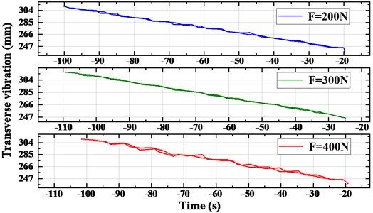
4.2. Influence of transverse vibration
It can be seen from the curve fluctuation and data of the motion trajectory diagram that the transverse vibration amplitude of DE and FG belt section is large. And the amplitude of FG belt section is the most obvious, so it is taken as the analysis object. Fig. 14 shows the transverse vibration amplitude of FG band under different initial tension of 200 N, 300 N, 400 N, respectively. With the increase of initial tension from 200 N to 400 N with 100 increments, the maximum vibration of FG belt section is 1.098 mm, 0.955 mm and 1.274 mm respectively. When the initial tension is small, the synchronous belt and pulley are not closely meshed, resulting in large transverse vibration. While the tension difference of the slack and tight sides becomes larger when the initial tension is large enough, the fluctuation of camshaft load torque will be intensified, resulting in large transverse vibration of the synchronous belt. Meanwhile, the larger tension will cause the contact stress of belt teeth increase and shorten the lifespan of synchronous belt.
Fig. 14The selection of the analyzed belt segment and the nonlinear amplitude fluctuation of transverse vibration
a) Motion track
b) Amplitude fluctuation
4.3. Influence of transmission error
The initial tension variation of the synchronous belt would affect the angular speed of the camshaft, producing transmission error of the system. The greater the initial tension, the closer the engagement between the belt and the pulley, and the smaller the transmission error. Otherwise, it will also increase of belt tooth stress, reducing the service life and dynamic performance of the synchronous belt. Fig. 15 shows the angular velocity fluctuation of camshaft under different initial tension conditions. We can obtain from the figure that the angular velocity fluctuation of camshaft is small when the initial tension 300 N, and the maximum fluctuation amplitude is 9.3395 rad/s. As the initial tension is getting smaller, the belt and pulley are not closely meshed, resulting in the increase of meshing slip. Therefore, the angular velocity of camshaft fluctuates greatly and the transmission error is large. When the initial tension is large, the elongation of the synchronous belt fluctuates greatly, resulting in large belt tension fluctuation. Combing with transverse and longitudinal vibration, the angular velocity fluctuation of the camshaft becomes larger. However, through increasing the initial tension can effectively reduce the meshing slip rate between the belt teeth and the tooth groove, so as to reduce the longitudinal vibration. Therefore, the fluctuation amplitude of camshaft angular velocity when the initial tension 400 N is less than that 200 N.
Fig. 15Nonlinear fluctuation of camshaft angular velocity
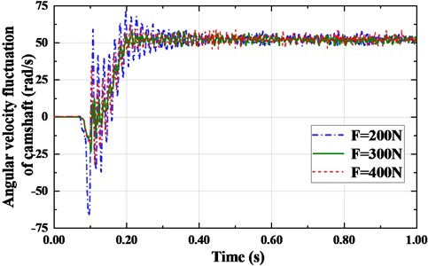
Fig. 16Nonlinear fluctuation of camshaft torque amplitude
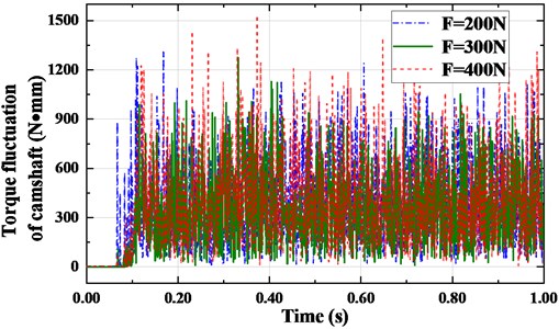
The angular velocity of camshaft fluctuates when the synchronous belt is meshing with the pulley, and its torque is affected and produces nonlinear fluctuation. The transverse and longitudinal vibration of the belt caused by the initial tension will also have an indirect impact on the torque fluctuation of the camshaft. Fig. 16 shows the camshaft torque fluctuation under different initial tensions. The cam torque fluctuation is positively correlated with the camshaft angular velocity. The greater the initial tension, the stronger the camshaft torque fluctuation. When the initial tension 400 N, the camshaft torque fluctuates intensely, and the amplitude reaches up to 1766.1753 N·mm. When the initial tension is smaller, the belt does not mesh closely with the pulley, the slip rate of the synchronous belt increases, and the contact force between the belt teeth and the cogging of the pulley decreases. Therefore, when the initial tension 200 N, the angular velocity of the camshaft fluctuates greatly, and the torque fluctuation amplitude is smaller than that 400 N, where the maximum amplitude is 1711.1572 N·mm.
4.4. Influence of interference fluctuation
Combing with transverse vibration, longitudinal vibration and contact stress fluctuation, the belt and pulley would produce boundary interference. The interference level and could reflect the vibration characteristics and stress distribution of the synchronous belt. Fig. 17 shows the interference between the synchronous belt and each pulley under different initial tensions. With the increase of initial tension from 200 N to 400 N, the maximum interference depths are 0.4846 mm, 0.4129 mm and 0.4622 mm respectively. The contact stress between belt and pulley is proportional to the initial tension, and the interference depth will be larger under the action of system vibration. When the initial tension is small, the transverse and longitudinal vibration of the synchronous belt is large, and the impact frequency between the belt teeth and the belt tooth groove is high. Therefore, the slip rate of the belt teeth is high, resulting in wide amplitude of the interference depth.
Fig. 17Nonlinear variation curve of interference depth
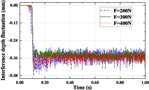
Fig. 18Nonlinear fluctuation law of interference velocity
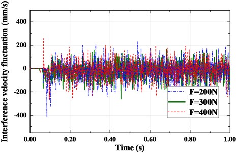
The interference speed reflects the contact frequency between the belt and the pulley, that is, the vibration frequency of the synchronous belt. The higher the vibration frequency would induce more contact frequency of the synchronous belt and the pulley teeth, causing more intense stress fluctuation of the synchronous belt and shorter service life. Fig. 18 shows the interference speed fluctuation between the synchronous belt and each pulley under different initial tension. With the increase of initial tension, the maximum fluctuation amplitudes are 689.6139 mm/s, 502.3982 mm/s and 665.6592 mm/s respectively. When the initial tension is large, the cogging engagement between the belt and the pulley is closer, so the contact stress between the belt and the pulley is greater, and the interference speed fluctuation is larger. When the tension is smaller, the vibration frequency of the synchronous belt becomes higher, inducing a higher impact frequency between the belt and the pulley, so as the bigger interference speed. There is a positive correlation between interference velocity fluctuation and interference fluctuation. Therefore, when the initial tension 300 N, the amplitude of interference velocity fluctuation is small.
To sum up, too small or too large initial tension would have a negative impact on the dynamic performance of the timing system. When the initial tension 300 N, the load distribution of the belt teeth is more uniform, the stress on the tooth root is smaller, and the vibration characteristics are better, which would induce lower transmission error and better dynamic performance.
5. Conclusions
Based on RU arc tooth synchronous belt meshing transmission, we established the timing system model of in-line four cylinder engines. The effect of the external load conditions on the timing system are analyzed through multi-body dynamics. And the effects of external load conditions on belt tooth stress, system transverse vibration, the error of the transmission and interference fluctuation dynamic performance are explored. The above research on synchronous belt is the same as the conclusion obtained in literature [11], and the belt tooth stress is concentrated in the tooth root area. Based on the research, the timing system composed of multiple pulleys is analyzed. The following conclusions are drawn:
1) The contact stress between the belt and the crankshaft pulley is greater than that with the camshaft pulley during the timing belt meshing transmission. The stress concentration is always produced at the tooth root. The crankshaft speed and the initial tension of the belt affect the meshing frequency and impact frequency of the belt teeth.
2) The transverse vibration amplitude of the belt section between the inlet camshaft and the guide idler 2 is large. The crankshaft speed and initial tension affect the meshing frequency and contact clearance between the belt and the pulley, which has a great impact on the transverse vibration.
3) The contact stress between the belt tooth and the tooth groove of the pulley is affected by the crankshaft speed and initial tension. The belt tooth slip rate and the tension difference at the slack and tight edge of the belt have a fluctuating impact on the camshaft angular speed and torque, resulting in transmission error.
4) The interference is affected by the contact stress between the synchronous belt and the pulley and the vibration frequency of the belt. The greater the contact stress, the worse the meshing performance of the belt and pulley, which would shorten the lifespan of the timing system.
5) When the crankshaft speed 2000 r/min and the initial tension 200 N, the stress fluctuation amplitude of the belt tooth root is smaller and the load distribution is more uniform. Meanwhile, the interference fluctuation is more stable, which also confirms the good reflection of stress. Under these conditions, the vibration characteristics of the synchronous belt are better and the transmission error is lower. Therefore, the meshing performance and dynamic performance are better.
References
-
Wu Y. Z., “The state-of-the-art in the production of drive belt,” (in Chinese), Journal of Mechanical Transmission, Vol. 37, No. 8, pp. 4–9, 2013.
-
G. Gerbert, H. Jo¨Nsson, U. Persson, and G. Stensson, “Load distribution in timing belts,” Journal of Mechanical Design, Vol. 100, No. 2, pp. 208–215, Apr. 1978, https://doi.org/10.1115/1.3453902
-
M. Kagotani, T. Koyama, H. Ueda, T. Aida, and T. Hoshiro, “Load distribution on toothed belt drives under a state of initial tension,” Bulletin of JSME, Vol. 27, No. 230, pp. 1780–1787, 1984, https://doi.org/10.1299/jsme1958.27.1780
-
M. Kagotani, H. Ueda, and T. Koyama, “Transmission error in helical timing belt drives (case of a period of pulley pitch),” Journal of Mechanical Design, Vol. 123, No. 1, pp. 104–110, Mar. 2001, https://doi.org/10.1115/1.1326916
-
M. Kagotani and H. Ueda, “Transmission error in synchronous belt with resonance under installation tension,” in ASME 2011 International Mechanical Engineering Congress and Exposition, Jan. 2011, https://doi.org/10.1115/imece2011-63296
-
M. Kagotani and H. Ueda, “Influence of installation tension on transmission error due to resonance in a synchronous belt,” Journal of Mechanical Design, Vol. 137, No. 8, Aug. 2015, https://doi.org/10.1115/1.4030204
-
H. Takagishi, H. Yoneguchi, Martin Sopouch, and I. Thiele, “Simulation of belt system dynamics using a multi-body approach: Application to synchronous belts and V-ribbed-belts,” in 10th Conference "Timing Belt Gears", Sep. 2005.
-
Wang F. et al., “Transmission analysis of an arc teeth synchronous belt considering the complex contact conditions,” (in Chinese), Mechanical Science and Technology for Aerospace Engineering, Vol. 28, pp. 496–499, 2009.
-
Li Z. G., Li H., Shi Y. C., and Ying J. L., “Research on dynamic simulation analysis of industrial 3M arc teeth synchronous belt,” (in Chinese), Journal of Changchun University, Vol. 25, No. 4, pp. 9–12, 2015.
-
Guo J. H. et al., “Transmission accuracy of synchronous belt based on RecurDyn,” (in Chinese), Journal of Mechanical Strength, Vol. 4, pp. 115–120, 2017.
-
Guo J. H. et al., “Optimization design of the new type double helical tooth synchronous belt and pulley structure parameter,” (in Chinese), Journal of Mechanical Transmission, Vol. 42, No. 12, pp. 60–64, 2018.
-
Guo J. H., Wei L., Cao Z. L., and Jiang H. Y., “Research of the meshing drive performance of new arc tooth synchronous belt based on RecurDyn,” (in Chinese), Journal of Mechanical Transmission, Vol. 43, No. 1, pp. 1–4, 2019.
-
G. Yang, L. Yang, and M. Cao, “Simulation analysis of timing belt movement characteristics based on RecurDyn,” Vibroengineering Procedia, Vol. 22, pp. 13–18, Mar. 2019, https://doi.org/10.21595/vp.2019.20561
-
R. Fan, M. Li, J. Guo, Q. Hu, Z. Cao, and M. M. Blum, “Dynamic performance simulation research of dual overhead synchronous belt drive system,” Journal of Computational Methods in Sciences and Engineering, Vol. 20, No. 4, pp. 1097–1107, Jan. 2021, https://doi.org/10.3233/jcm-204249
-
S. Passos, L. Manin, D. Remond, O. Sauvage, L. Rota, and E. Besnier, “Investigation on the rotational dynamics of a timing belt drive including an oval driving pulley,” Journal of Vibration and Acoustics, Vol. 143, No. 5, Oct. 2021, https://doi.org/10.1115/1.4050527
-
M. Khazaee, A. Banakar, B. Ghobadian, M. A. Mirsalim, and S. Minaei, “Remaining useful life (RUL) prediction of internal combustion engine timing belt based on vibration signals and artificial neural network,” Neural Computing and Applications, Vol. 33, No. 13, pp. 7785–7801, Jul. 2021, https://doi.org/10.1007/s00521-020-05520-3
-
G. Sequenzia, M. Calabretta, I. Assenza, and S. M. Oliveri, “Dynamic behaviour modelling of an internal combustion engine water pump transmission belt drive,” International Journal of Vehicle Performance, Vol. 7, No. 1/2, p. 170, 2021, https://doi.org/10.1504/ijvp.2021.10035878
-
W.-B. Shangguan and X.-K. Zeng, “Modeling and validation of rotational vibration responses for accessory drive system-part II: simulations and analyses,” Journal of Vibration and Acoustics, Vol. 135, No. 3, Jun. 2013, https://doi.org/10.1115/1.4023140
-
Long S. B. et al., “Modeling and analysis for dynamic performances of engine timing belt driving systems,” (in Chinese), Transactions of CSICE, Vol. 42, No. 12, pp. 60–64, 2019.
-
Shi Y. C. et al., “Simulation analysis and experimental study of the automobile synchronous belt drive noise,” (in Chinese), Journal of Mechanical Transmission, Vol. 40, No. 9, pp. 145–149, 2016.
About this article

This project is supported by National Natural Science Foundation of China (51705266), The Ministry of Education Industry-University Cooperation Collaborative Education Project (201901145012), Basic scientific research business expenses of undergraduate universities in Heilongjiang Province (135409604, 135409102), Higher Education Teaching Reform Research Project of Heilongjiang Provincial Department of Education (SJGY20190715), Graduate Innovative Research Project (YJSCX2020055).
