Abstract
Ultrasonic stitching is a thread-free and green technology for stitching fabrics, which uses the vibration energy of high frequency to transform it into heat at the joint to achieve local fusion. This paper provides the conceptual design and experimental validation of a roller-based ultrasonic sewing system for thermoplastic and composite textile. This work introduces a portable roller-type ultrasonic actuator coupled with a physics-based thermal model which allows the controlled and threadless joining of textiles, which is the main innovation of this paper. When operated at 27 kHz, 100 W and contact pressure of 5 MPa, the method gives maximum lap shear strengths of 86 N for polyester and 67 N for cotton + LDPE. The measured results define the process window and show the possibility of low-waste industrial utilization. Novelty: (I) a small size ultrasonic stitching unit based on the roller technology; (II) a closed-form thermal model for the relationship between energy input and joint strength; (III) validated process parameters towards a sustainable textile bonding application.
1. Introduction
The assembly of textile materials is a critical step in technical, medical, and protective apparel production. Traditional methods – needle stitching and adhesive bonding – often damage delicate fibres, require consumables, and generate waste.
Ultrasonic welding represents a clean, rapid, and contact-safe alternative: mechanical vibration at ultrasonic frequencies melts the polymer locally, bonding the layers without additional materials [1].
The present study addresses two objectives:
1) To design and test a roller-based ultrasonic stitching mechanism suitable for continuous seams.
2) To establish a predictive model connecting frequency, pressure, and seam strength to support process optimisation.
This research fits squarely within the journal’s scope on advanced manufacturing and materials engineering by combining theoretical modelling with applied process development for sustainable textile technologies [2].
2. Materials and methods
Theoretical Predictions Heating is calculated with a certain theory but the calculations are always complicated. The object has therefore been to arrive at a new equation which provides a simplified solution which can then be used in the design of machinery: such as in the design of radiators and other apparatuses for the machine, such as rollers.
Two systems of materials were studied: (I) polyester fabric, (II) cotton + LDPE. All processing steps and testing procedures followed the procedures as described herein.
In an ultrasonic movement, energy losses occur in the form of heat in the material traversed by the acoustic wave. The main mechanisms that are responsible for this thermal generation are viscous dissipation, relaxation phenomena and hysteresis losses produced during the periodic deformation of the fabric [3].
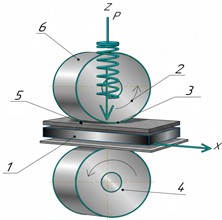
The polymer strip (5) is fed between both rollers (1, 2) by the stitching unit, which suffices to feed the fabric layers (3,4) through the gap (see Fig. 1). Under the ultrasonic vibration, the fabrics and polymer are compressed by the upper roller (2) against the spring (6). The polymer would melt and enter the pores inside the fabric due to the combined effect of pressure and ultrasound. After ultrasonic excitation has stopped, the polymer hardens, therefore creating strong bonding between the layers of the fabric [4], [5].
Fig. 1A schematic diagram of a stitching unit on an ultrasonic sewing machine
3. Equations
Identification of the temperature distribution along the seam can be determined by the internal heat that is produced by the ultrasonic vibration. In simplifying the problem, we use the one-dimensional equation of heat conduction at steady state and ignore the transient term. This enables emphasis on the spatial temperature distribution due to the heat source of the ultrasonics [6]. The general process, as it is, remains inherently non-stationary owing to the time dependence; however, a simplified solution was realised by assuming that the heat source is constant and uniform where the heat source is placed inside the material [7].
Under steady state condition, uniform generation of heat internally through thickness :
Convective boundaries at :
General solution:
Symbols: (K), (W·m-3), (W·m-1·K-1), (W·m-2·K-1), (m).
The constants and are found by the boundary conditions. For instance, when there is convection on both surfaces:
Under the isothermal boundary conditions , , the solution becomes:
and are constants of integration and are found using the boundary conditions of the problem [8]. The thermal conductivity of the material is indicated by , which is a constant and is related to the internal heat generation coming from the ultrasonic welding.
By implementing specified values, = 0, 1 and = 0, it is identified, and so, the general formula is complete and afterwards given by:
where – width of the roller (m); – the length of the contact (nip) was measured in meters using pressure-sensitive film and checked with the naked eye. The mechanical results are given as peak lap-shear load (N) and, if applicable, normalized strength (N/mm) based on bonded width.
The interface peak temperature and gradients of the process window are calculated from Eqs. (2)-(4).
Experimental work was carried out on cotton (150 g m-2, 2 mm thick) and polyester (120g m-2, 1 mm thick) fabrics. For the cotton specimens, low density polyethylene (LDPE) film was used as an interlayer [9]. The stitching machine (Fig. 1) feeds a polymer ribbon between two rollers, the polymer is softened by ultrasonic excitation from a horn beam, penetrates the pores of the fabric and solidifies after the vibration is stopped, thus creating a strong joint.
Thermal model:
The theoretical temperature distribution throughout the bonded interface was calculated by means of a one-dimensional heat-conduction equation at steady state coupled with heat generation within the thickness of the interface (Eqs. (1-5)).
The predicted best oscillation frequency was about 23.45 kHz and the squeeze force was 43 N, based on the fabric parameters ( 1500 kg m-3, 1300 J kg-1 K-1, 0.04 W·m-1·K-1, 0.3 K·m2·W-1).
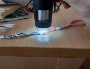
Ultrasonic generator (20-50 kHz range, 100-200 W), roller diameter 1.5 mm. Contact pressure 5-25 MPa; pulse duration 1.0 s. We looked at the weld quality using a 50× USB microscope (Fig. 4).
4. Results
To understand the efficiency of ultrasonic cross-linking of textile materials, test procedures were carried out on joining cotton, silk and polyester fabric samples on a mini-ultrasonic welding machine located in the laboratory where test procedures were conducted accordingly [10].
In order to determine the optimal modes of ultrasound welding, fabric samples were taken of cotton fabric (article number CF-100, density 150 g/m2, thickness 2 mm) and of polyester fabric (article number PE 100, density 120 g/m2, thickness 1 mm) and also in order to evaluate the characteristics of strength of the obtained joints, the stitching of fabric samples was conducted on the test bench in the laboratory using ultrasound and Stitching on cotton fabric was done in Fig. 2 with high-pressure polyethylene LDPE that was used as a cushioning material. The diameter of the contacting rollers is 1.5 mm; therefore, the thickness of the seam ranged between 1.5 and 2 mm on average. There is no cushioning material at the stitching of polyester. The loading pressure between the rollers (Table 1).
Fig. 2An overlay stitch
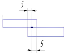
Table 1The frequencies considered varied between 20 and 50 kHz with 5 kHz intervals; contact pressures varied from 5, 10, 15, 20 and 25 MPa; power levels used were 100, 150 and 200 W
Fabric | Contact pressure, MPa |
Cotton | 5,10,15,20,25 |
Polyester | 5,10,15,20,25 |
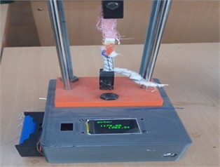
Fig. 3Tissue stitching experimental ultrasound machine placed at the Tashkent Institute of Textile and Light Industry. Photo by M.M. Allamov, TITLI Materials Testing Laboratory, Tashkent, Uzbekistan, December 2023
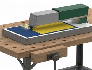
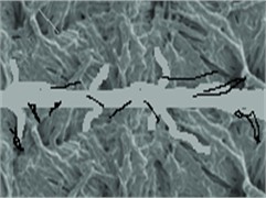
Fig. 4Experimental set up for microscopic characterization of the weld interface using a USB digital microscope; microstructure of the ultrasonic weld interface at 50x magnification showing the fibre-polymer interface. Photos by O. Khudoynazarov, TITLI Materials Testing Laboratory, Tashkent, Uzbekistan, December 2023
The ultrasonic vibration generator operated at the input power levels of 100, 150 and 200 W.
The selected range was meant to encompass the capabilities of the equipment.
Contact pressures were kept in the range of 5-25 MPa, a level consistent with the established guidelines for ultrasonic welding of textile materials. The pulse duration of ultrasonic exposure was maintained at 1.0 s. Visual assessment of all the weld samples was performed with both natural and artificial lighting to monitor weld quality. Moreover, the joint-zone structure was examined under 50x magnification with a USB microscope (Fig. 4). Standard observations (pore and defect formation) were reported (Figs. 5, 6).
Define (once in Methods):
where , – bonded width (m), – length of contact (nip) under load (m) through pressure sensitive film or high resolution imprint.
If 50 N and 10 mm2 = 10×10-6 m2, then 50/10×10-6 = 5000000 Pa = 5 MPa.
The load on the process is expressed as contact pressure (MPa) calculated as , where is the nip area of width roller width w times the measured contact length at the set load. was measured from pressure-sensitive film and then was checked optically. Unless otherwise stated all process conditions are measured in MPa, mechanical test results are given in terms of the peak lap-shear load (N) and if applicable in terms of the normalized strength (N/mm) based on the bonded width.
Fig. 5Microstructural analysis of a sound ultrasonic weld subjected to tensile failure at 50× magnification: a) an intact weld structure showing penetration of a thermoplastic polymer between fibre bundles; b) a rupture surface showing interfacial delamination (arrows) and fibre separation. Images taken by N. Palvannazirova of the Materials Testing Laboratory, Tashkent Institute of Textile and Light Industry, Tashkent, Uzbekistan, December 2023
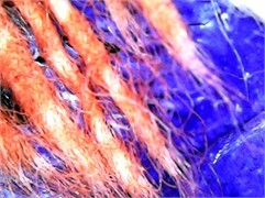
a)
b)
The mechanical tests of welded joints of textile materials were conducted on the developed tearing machine (Fig. 6) and a special machine with the velocity of movement of an active gripper of 50 mm·min-1, which demonstrated identical results 4. At the tests the breaking force of the specimens was registered (Fig. 6) [10].
Fig. 6Tensile testing of ultrasonic welded seams at 50 mm/min cross-head speed: custom testing apparatus using digital force - measurement system; Photographs taken by N. Palvannazirova Materials Testing Laboratory TITLI Tashkent Uzbekistan December 2023
Test results were statistically processed with:
The calculation of an average value of breaking force of each type of fabric and each mode of ultrasonic treatment on the basis of all received values.
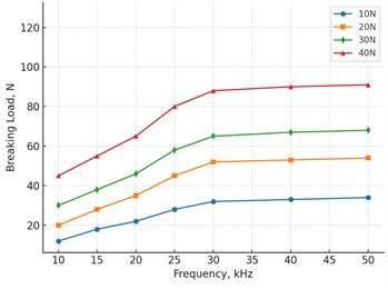
Microscopic and macroscopic investigations supported the homogeneous melting and impregnation of the polymer inside the pores of the fabric. Regression analysis (Fig. 7) showed that the breaking strength increased with applied pressure up to 5 MPa and then the relationship leveled off. Comparison of the resulting values with two samples Student’s t-test. All the calculations were carried out by using the OriginPro2019 package. The findings were that there were significant mean differences between jointing strengths based on different fabric types and different modes of jointing. Certain of the test results are given in Table 2.
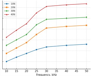
Fig. 7The breaking force increased with increasing contact pressure over the tested range and tended to become constant at the high end as shown
a)
b)
Table 2Test results
Fabric | Ultrasonic mode | Mean load, N | SD (N) | 95 % CI (N) | n |
Cotton+LDPE | 100 W; 5 MPa; 27 kHz | 67 | 6 | 59.6-74.5 | 5 |
Polyester | 100 W; 5 MPa; 27 kHz | 86 | 15 | 67.4-104.6 | 5 |
Note: – the limits of the confidence interval of the average value of breaking force are 95 %. – main score – average weld strength (N). – standard deviation (N), indicating reproducibility. – the limit of such a confidence interval, which considers both the errors and random aspects influencing the dispersion of the measured values, [N].
The optimum frequency supported by the model (23.4 kHz) is close to the experimentally used frequency (27 kHz) and, thus, supports the validity of the simplified analytical approach.
5. Discussion
Polyester exhibits good tensile strength thanks to its own thermoplastic character (direct fusion processes). The good agreement between the predicted and the observed frequencies supports the validity of the thermal model. In comparison with traditional sewing methods, ultrasonic stitching creates airtight seams without any needle perforation, has repeatable bonding capability, and reduces the amount of energy and material waste, which is in line with the current trend of sustainable textile processing.
6. Conclusions
The experiments were performed using a fixed geometry of the rollers, a pressure of 5 MPa, and a power of 100 W and the frequency was increased from 20 to 50 kHz with 5 kHz steps. For polyester and cotton+LDPE, the lap-shear strength increased up to ~27 kHz, flattened around 35 kHz and then decreased above ~40 kHz. Each data point 5 is reproduced five times; the markers represent the mean and the error bars represent the standard deviation (Table 2).
References
-
L. Zhuang, R. Talreja, and J. Varna, “Transverse crack formation in unidirectional composites by linking of fibre/matrix debond cracks,” Composites Part A: Applied Science and Manufacturing, Vol. 107, pp. 294–303, Apr. 2018, https://doi.org/10.1016/j.compositesa.2018.01.013
-
J. Sattler and L. Froschauer, “Investigating the weldability of textiles using ultrasonic welding,” Journal of Engineered Fibers and Fabrics, Vol. 15, pp. 1–7, 2020.
-
A. Kumar, A. Suhail, and N. Ismail, “Optimization of process parameters for ultrasonic welding of polyester woven fabric,” Indian Journal of Fibre and Textile Research, Vol. 42, No. 4, pp. 425–428, 2017.
-
“Ultrasonic welding equipment.” Telsonic AG, https://www.telsonic.com
-
S. K. Bhudolia, G. Gohel, K. F. Leong, and A. Islam, “Advances in ultrasonic welding of thermoplastic composites: a review,” Materials, Vol. 13, No. 6, p. 1284, Mar. 2020, https://doi.org/10.3390/ma13061284
-
K. K. Chawla, “Composite materials: science and engineering,” in Materials Chemistry and Physics, Vol. 19, New York: Elsevier BV, 1988, pp. 299–300, https://doi.org/10.1016/0254-0584(88)90034-x
-
S. K. Bhudolia, K. K. Kam, P. Perrotey, and S. C. Joshi, “Effect of fixation stitches on out-of-plane response of textile non-crimp fabric composites,” Journal of Industrial Textiles, Vol. 48, pp. 1151–1166, 2019.
-
S. K. Bhudolia, S. Fischer, P. G. He, C. Y. Yue, S. C. Joshi, and J. L. Yang, “Design, manufacturing and testing of filament wound composite risers for marine and offshore applications,” Materials Science Forum, Vol. 813, pp. 337–343, Mar. 2015, https://doi.org/10.4028/www.scientific.net/msf.813.337
-
S. K. Bhudolia, P. Perrotey, and S. C. Joshi, “Enhanced vibration damping and dynamic mechanical characteristics of composites with novel pseudo-thermoset matrix system,” Composite Structures, Vol. 179, pp. 502–513, Nov. 2017, https://doi.org/10.1016/j.compstruct.2017.07.093
-
R. Matadi Boumbimba, M. Coulibaly, A. Khabouchi, G. Kinvi-Dossou, N. Bonfoh, and P. Gerard, “Glass fibres reinforced acrylic thermoplastic resin-based tri-block copolymers composites: Low velocity impact response at various temperatures,” Composite Structures, Vol. 160, pp. 939–951, Jan. 2017, https://doi.org/10.1016/j.compstruct.2016.10.127
About this article

The authors have not disclosed any funding.
The authors would like to thank the Tashkent Institute of Textile and Light Industry for letting them use their labs and helping them with technical issues.
The datasets generated during and/or analyzed during the current study are available from the corresponding author on reasonable request.
The authors declare that they have no conflict of interest.
