Abstract
As a core component of the automotive engine intake system, the throttle valve body is subjected to long-term engine vibrations. Defects such as gas pores and shrinkage pores in the die-cast part will cause uneven stiffness of the throttle valve body, and thus lead to fatigue failure due to local stress concentration under vibration loads. In this paper, the aluminium alloy was used as the die-casting alloy to design an efficient and simple die-casting mould for CH367B1 aluminium alloy throttle valve body. After measuring the target dimensions and conducting a preliminary analysis of the UG 3D drawing of the part, the size and structure of the valve body were analysed according to the 3D model of the part to select the appropriate parting surface. In the design process, the clamping force, chamber capacity, projected area and other parameters were calculated in order to select a suitable die-casting machine. Part-related dimensions and features were analyzed. Push-out mechanisms, molded parts, guide mechanisms, etc. were designed. The whole set of molds was obtained. Suitable casting systems were designed by calculating and checking references. Mold flow analysis was carried out using ProCAST2021 software. The optimal solution was selected by observing the liquid metal filling process and the distribution of defects, and then calibrated.
Highlights
- This paper systematically completes the design of the die casting mold for the CH367B1 aluminum alloy throttle valve body, taking into account its structural characteristics.
- The mold flow analysis is conducted from three aspects, namely the flow pattern of molten metal, temperature field distribution and defect distribution, using ProCAST2021 software.
- In the mold design, an angle pin side core-pulling mechanism is adopted to form the side hole of the throttle valve body, and the cavity is arranged in the moving mold part to avoid marks left by the ejector pin on the inner surface of the air-sealing valve body.
1. Introduction
Aluminum alloys are highly favored due to their low density, high strength, and excellent corrosion resistance [1], [2]. With these advantages, the material has been widely applied in various industrial fields such as aerospace, the automotive industry, and electronic products, serving as an important cornerstone for promoting technological progress and innovation [3], [4]. Along with the development of the manufacturing industry, the die-casting industry shows an inevitable trend of developing towards automation and intelligence [5]. Meanwhile, the industry is also actively researching new die-casting alloy materials [6], and leveraging computer technology to deeply explore the formation mechanisms of casting defects and design higher-quality die-casting molds, so as to reduce casting defects [7]-[9]. Aluminum alloy die-casting has attracted extensive attention and research on its application from numerous domestic and foreign clients due to its advantages such as high production efficiency and excellent part performance. In fields with high precision requirements for products, such as automobiles and aerospace, aluminum alloy die-castings are extremely widely used [10]. Developed countries started research on aluminum alloy die-casting mold design earlier, and have constructed a mature and perfect theoretical and practical system in terms of materials, molds, processes, etc. For example, European and American countries have reached a relatively high level in the application of computer-aided design (CAD) and computer-aided engineering (CAE) technologies for die-casting molds, which can realize the simulation and optimization design of the die-casting process, significantly improving the quality and production efficiency of die-castings. In addition, developed countries have also carried out research on the service life and sustainability of die-casting molds [11], [12], continuously exploring the application of new materials and technologies in composite materials and processing technology fields and processing technologies to promote the continuous development of die-casting technology. In terms of research abroad on the performance of mold materials, the focus is mainly on the improvement of surface treatment processes, high-performance mold steels, etc., aiming to enhance the service life and fatigue resistance of molds [13].
As a core component of the automotive engine intake system, the throttle valve body operates in an environment with long-term engine vibrations (typically within a frequency range of 50-2000 Hz). If the die-cast part has defects such as gas pores and shrinkage pores, it will cause uneven stiffness of the component, which further leads to local stress concentration under vibration loads and results in fatigue failure. This paper analyzes the structural performance of the CH367B1 aluminum alloy throttle valve body, comprehensively considering various factors such as the body's dimensions, materials, and mechanical properties to determine the design process. According to the product characteristics and requirements, appropriate process parameters and die-casting machines are selected. By simulating and analyzing the gating system and overflow system, the fluidity of the material during die-casting is ensured, and defects are avoided. Finally, the design of forming parts, structural parts, and ejection mechanisms is completed. The research in this paper lays a solid and reliable foundation for the optimized design, efficient production, and performance improvement of the CH367B1 aluminum alloy throttle valve body, while also providing valuable references for technical research and practice in related fields.
2. Materials and method
The die-casting part structure is composed of an irregular arc-shaped cavity, an irregular rectangular shell, and two circular holes. Among them, the maximum wall thickness at the cavity corners is 2.5 mm, the minimum wall thickness at the small holes on both ends is 1.4 mm, and the wall thickness of all other parts is uniformly 2 mm. The part has a volume of approximately 40.9 cm3 and external dimensions of 106 mm×102 mm×37 mm. In terms of molding method, the arc-shaped cavity and rectangular shell can be formed by one large core combined with two small cores, while the circular holes are formed independently by small cores. The dimensional tolerance is clearly specified as IT14 grade. In the ProCAST simulation analysis of this study, specific materials were used for the die-casting part and the mold respectively: YZAlSi12 aluminum alloy was selected for the die-casting part, and 3Cr2W8V hot-work die steel was selected for the mold. The 3D model of the CH367B1 part is shown in Fig. 1, and Fig. 2 illustrates the selected parting surface. Reasonable selection of the gate can achieve effective filling, improve die-casting efficiency, reduce mold costs, and lower mold manufacturing difficulty [14]. Different gating system designs have distinct impacts on the quality of die-cast parts after forming. In this design, only the arrangement of the runner is altered. The first type is the commonly used fan-shaped runner, while the second type converts the runner into a straight configuration. The ProCAST software is employed to conduct mold flow analysis on the designed different gating systems.
Table 1Chemical element composition content of YZAlSi12 (wt.%)
Element | Fe | Si | Mn | Ni | Cu | Pb | Zn | Sn | Mg | Al |
Content | ≤1 | 10~13 | ≤0.35 | ≤0.5 | ≤0.1 | ≤0.1 | ≤0.4 | ≤0.15 | ≤0.1 | Balance |
3. Results and discussion
Export the designed UG file in IGES format, open the file with the Visual-Mesh module of ProCAST2021 software, and create surface meshes. Set the mesh size of the die-casting part and inner gate to 2 mm, the runner and sprue to 3 mm, and the remaining parts to 10 mm. Create surface meshes. After completion, the model has 31,270 surface meshes and 861,432 volume meshes. After the mesh creation was completed, the Visual-Cast module in the ProCAST software was accessed, and the gravity direction was set to the – direction.
Fig. 13D drawings of die-cast parts
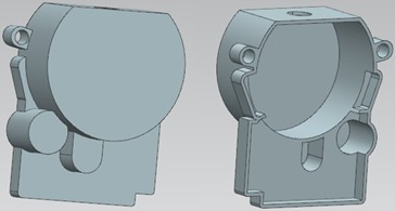
Fig. 2Parting surface

3.1. Flow pattern
The flow velocity of molten metal during die casting has a crucial impact on the quality, performance, and production efficiency of die-cast parts . The velocity fields of the two gating system schemes are shown in Fig. 3, representing the flow patterns of molten metal at 10 ms, 25 ms, and 28 ms, respectively. As shown in Fig. 3(a), in the early stage of mold filling, the molten metal enters the cavity through the inner gate. Due to the vertical corner of the shell, the flow velocity there is as high as 90 m/s. The filling of the lower-left corner and the protruding cavity is obstructed. In the late filling stage, as the lower-left corner was previously underfilled while other parts were basically filled, the flow velocity in this area accelerates. When the filling is about to end, all parts except the overflow groove have been filled. The cross-sectional area where the overflow groove contacts the casting is small, causing the flow velocity here to increase rapidly, and the velocity from the inner gate to the overflow groove also increases. As shown in Fig. 3(b), the flow velocities at the inner gate and the lower part of the part are both high throughout the mold filling process, indicating that the runner design of this scheme is unreasonable. In the late filling stage, the overflow groove is already full, but the protruding cavity and the lower-right corner remain unfilled.
3.2. Temperature field
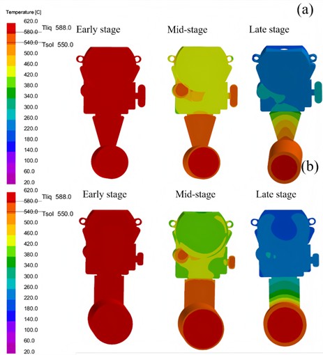
The temperature fields of the two gating system schemes are shown in Fig. 4, where “early stage” and “mid-stage” refer to the temperatures at 4 s and 8 s after pouring starts, respectively, and “late stage” is the time required for the molten metal to cool to the mold operating temperature, which is 37.2 s and 35.6 s, respectively. As shown in Fig. 4(a), during the early cooling stage immediately after filling, the temperature field observation shows that the temperature at filling is approximately 588 °C. During the mid-cooling stage, it is observed that the slowest temperature drop occurs in the circular cavity at the lower-left part, which was filled slowly. In the late stage, when cooling is about to be completed, the first part to cool down is the thin-walled section at the upper end. As shown in Fig. 4(b), the temperature field of Scheme 2 is basically the same as that of Scheme 1. The temperature immediately after filling in the early stage is about 588 °C, which should be caused by the mold absorbing part of the heat and certain temperature loss during filling, resulting in the filling temperature being lower than the set temperature. The slowest cooling part in the mid-stage is still the circular cavity at the lower-left part, and the first part to cool in the late stage is the thin-walled section at the upper end.
Fig. 3Velocity field: a) scheme 1, b) scheme 2
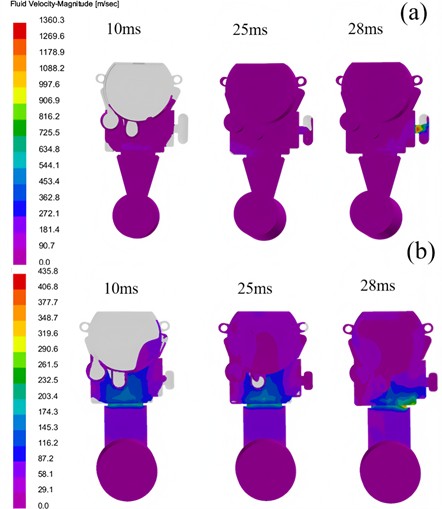
Fig. 4Temperature field: a) scheme 1, b) scheme 2
3.3. Die casting defects
The porosity distribution and potential locations are shown in Fig. 5. As indicated in Fig. 5(a), when using a fan-shaped runner, defects first appear at the junctions of the circular hole and circular cavity with the large cavity. The part has a simple structure and thin wall thickness, resulting in fewer defects. At the junctions of the circular cavity/hole and the large cavity, the molten metal flow is severely obstructed. Fig. 5(b) shows that when using a straight runner, defects first occur at the junctions of other cavities with the large cavity. However, Scheme 2 has slightly more defects than Scheme 1, notably in the ear-shaped cavity on the right. Taking all factors into account, the gating scheme in Scheme 1 is selected.
Fig. 5The defect distribution in different schemes
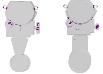
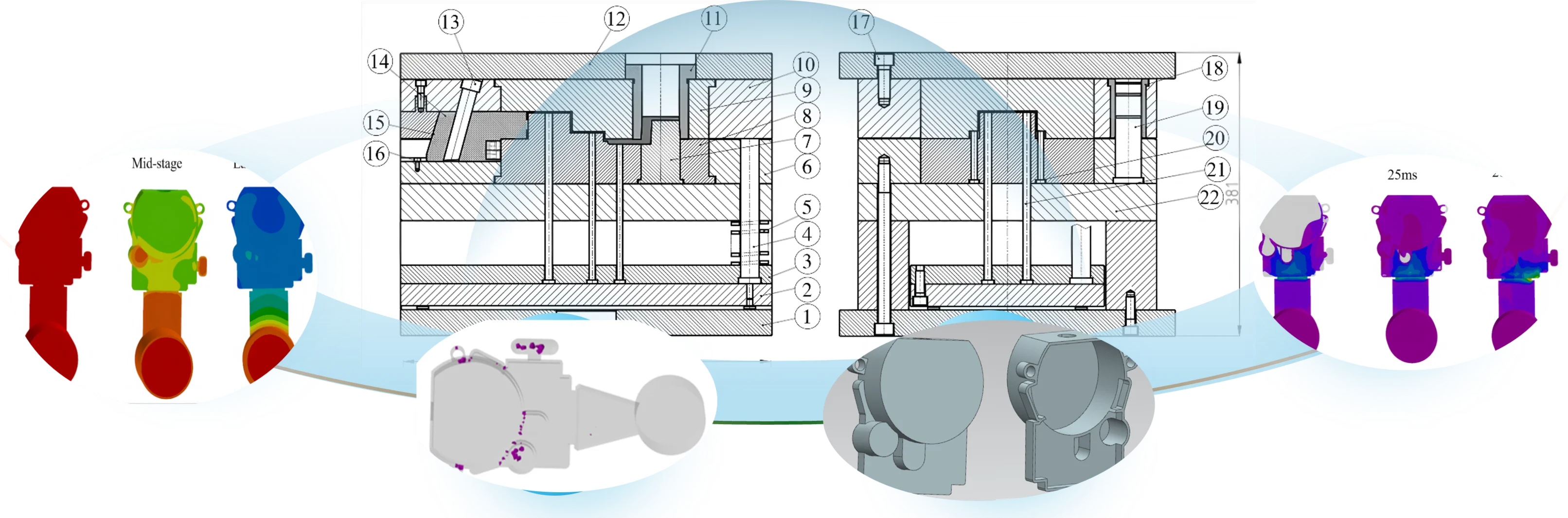
Fig. 6Assembly drawing: 1 – moving mold base plate; 2 – ejector plate; 3 – ejector retainer plate; 4 – return pin; 5, 22 – spring; 6 – moving mold plate; 7 – gate core; 8 – core; 9 – cavity; 10 – fixed mold plate; 11 – sprue bushing; 12 – fixed mold base plate; 13 – angle pin; 14 – slider; 15 – wedge block; 16 – limit screw; 17 – screw; 18 – guide pillar; 19 – guide bush; 20, 21 – ejector pin; 22 – support plate
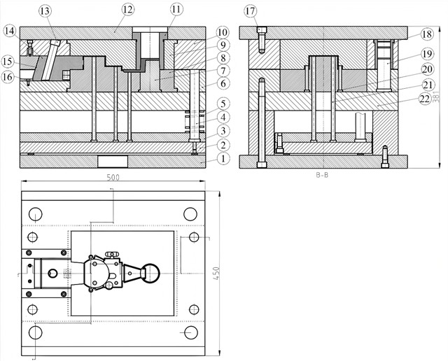
3.4. Assembly drawing
The die-casting mold mainly includes molding components, gating system, overflow and venting system, core-pulling mechanism, etc. Molding components include the core and cavity, which determine the shape and dimensional accuracy of the die-cast part. The gating system connects the shot chamber to the mold cavity, guiding the molten metal into the cavity and regulating the metal flow. The overflow groove discharges gases, stores the front-flow cold metal and waste residues. The mold base includes supporting and fixing components, guiding components, and ejection mechanism. The core-pulling mechanism works together with the ejection mechanism to remove the casting during mold opening, while other bolts, pins, etc., are used to fix and connect various parts of the mold. The structure of the designed mold is shown in Fig. 6.
4. Conclusions
In this design, the structural analysis and process parameter selection of the throttle valve body die-cast part were first carried out, and the J1116 die-casting machine was selected for production. To ensure the surface quality of the inner cavity of the throttle valve body, the cavity was placed in the moving mold part to avoid marks left by the ejector pins on the inner surface of the air-sealing valve body during ejection. Two gating schemes were designed, and mold flow analysis was performed using Procast software to determine the fan-shaped sprue gating scheme. An angle pin side core-pulling mechanism was used to form the side hole of the air-sealing valve body. However, this paper only conducts theoretical simulation analysis on the die-casting mold and has not yet verified the analysis with physical objects. In subsequent research, physical prototypes will be produced and relevant experiments will be carried out to further verify the reliability of the simulation results.
References
-
J. Shu, H. Gong, J. Peng, P. Song, and J. Zhang, “Optimization design of gating and overflow system for die-casting mold of aluminum alloy crankshaft rear end cover,” Materials Science and Technology, Vol. 31, pp. 71–80, Jun. 2023, https://doi.org/10.11951/j.issn.1005-0299.20220176
-
S. Zhao and Y. Shi, “Effect of different heat treatment on microstructure and mechanical properties of ADC12 die-casting aluminum alloy,” Hot working technology, Vol. 46, pp. 230–233, Mar. 2017, https://doi.org/10.14158/j.cnki.1001-3814.2017.06.062
-
R. Chu and J. Guo, “Improvement of microstructure and mechanical properties bycomposition minor adjustment of die-cast YL112 aluminum alloy,” Light Alloy Fabrication Technology, Vol. 48, pp. 19–26, May 2020, https://doi.org/10.13979/j.1007-7235.2020.01.004
-
Q. Liu and L. Lan, “Application and development of aluminum and magnesium alloy die-cast parts in automobile industry,” Automobile Digest, Vol. 2, pp. 50–55, Feb. 2024, https://doi.org/10.19822/j.cnki.1671-6329.20230114
-
T. Debroy et al., “Additive manufacturing of metallic components – process, structure and properties,” Progress in Materials Science, Vol. 92, pp. 112–224, Mar. 2018, https://doi.org/10.1016/j.pmatsci.2017.10.001
-
S. Ford and M. Despeisse, “Additive manufacturing and sustainability: an exploratory study of the advantages and challenges,” Journal of Cleaner Production, Vol. 137, pp. 1573–1587, Nov. 2016, https://doi.org/10.1016/j.jclepro.2016.04.150
-
S. C. Ligon, R. Liska, J. Stampfl, M. Gurr, and R. Mülhaupt, “Polymers for 3D printing and customized additive manufacturing,” Chemical Reviews, Vol. 117, No. 15, pp. 10212–10290, Aug. 2017, https://doi.org/10.1021/acs.chemrev.7b00074
-
S. C. Altıparmak and B. Xiao, “A market assessment of additive manufacturing potential for the aerospace industry,” Journal of Manufacturing Processes, Vol. 68, pp. 728–738, Aug. 2021, https://doi.org/10.1016/j.jmapro.2021.05.072
-
Z. Yu, X. Deng, J. Qiao, D. Zhou, and L. Li, “Direct fabrication of microcantilever structures with high shape accuracy using projection-based stereolithography,” 3D Printing and Additive Manufacturing, Vol. 11, No. 2, pp. e688–e697, Apr. 2024, https://doi.org/10.1089/3dp.2022.0236
-
R.-C. Kim, K.-R. Hong, J.-Y. Yang, and W.-C. Yang, “High-pressure die casting process optimization for improving shrinkage porosity and air entrainment in carburetor housing with aluminum alloy using Taguchi-based ProCAST simulation and MADM-based overall quality index,” The International Journal of Advanced Manufacturing Technology, Vol. 132, No. 1-2, pp. 893–906, Mar. 2024, https://doi.org/10.1007/s00170-024-13428-8
-
R. Lu and C. Lu, “Research on the design method of precision die casting mold for magnesium alloy parts based on deep learning,” China High and New Technology, Vol. 12, pp. 42–44, Jul. 2025, https://doi.org/10.13535/j.cnki.10-1507/n.2025.12.09
-
Z. Dai, M. Ma, and Y. Zhu, “Failure analysis and design optimization of die casting mold for zinc alloy thin-wall part,” Special Casting and Nonferrous Alloys, Vol. 45, pp. 1263–1270, Aug. 2025, https://doi.org/10.15980/j.tzzz.t20240008
-
Y. Zheng, G. Yuan, J. Kang, G. Jia, and Y. Zhao, “Numerical analysis of the comprehensive effect of continuous casting process parameters on the continuous casting billet remelting,” Numerical Heat Transfer, Part A: Applications, Vol. 85, No. 2, pp. 270–286, Jan. 2024, https://doi.org/10.1080/10407782.2023.2181895
-
T. Wang, J. Huang, K. Yu K., L. Chen, H. Fu, and S. Yao, “Influence of inner gate flow velocity in die-casting mold on filling state and solidification quality,” China Foundry Machinery and Technology, Vol. 56, pp. 58–62, Nov. 2021, https://doi.org/10.3969/j.issn.1006-9658.2021.06.013
About this article

The authors have not disclosed any funding.
The datasets generated during and/or analyzed during the current study are available from the corresponding author on reasonable request.
The authors declare that they have no conflict of interest.
