Abstract
Two kinematic diagrams are presented, consisting of two combined toggle mechanisms and a piston pump. Kinematic calculations of the moving link parameters for both kinematic diagrams resulted in the determination of the displacement of the working and idle stroke lengths of the piston as a function of the toggle mechanism swing angle and the change in the toggle length and crank radius of the piston pump. The numerical value of the coefficient of the average toggle mechanism slider velocity, 2, and the displacement of the piston stroke were obtained: for a toggle-piston pump, 1.25, and for a crank-toggle mechanism, 0.7 m. Various asymmetric phase angles were calculated for the working and idle strokes of the slider during rotation of the toggle mechanism crank for both kinematic diagrams. The relationship between the center distance and the position of the fixed support point of the crank axis of rotation to the support point of the rocker arm is obtained. The numerical values of the stroke displacement , linear velocity , and acceleration of the pump piston for both kinematic diagrams of the rocker-piston pump mechanism are presented in tabular form by numerical values and in kinematic diagrams.
1. Introduction
In the technological processes of mortar pumps, for the best transportation of the mortar mixture, a crank-slider mechanism is used to drive the working element of a piston pump [1]. In the work [2], two variants of the kinematic diagram of a rotating yoke are presented; here, as a result of the synthesis of this mechanism, the optimal geometric parameters for both yoke mechanisms are given. In the kinematic studies [3], the use of a planetary mechanism for driving the working element of a mortar mixer is considered. Foreign researchers [4] are conducting work on combining two mechanisms: a crank-slider mechanism and a yoke mechanism for a pumping unit for pumping oil. Works [5, 6] are also being studied using a planetary mechanism for the working element of a pump for pumping viscous and heterogeneous liquids. The works [7, 8] present the results of scientific research on the operation of pumping equipment at drainage stations, in which an increase in vibration is observed due to hydro abrasive and cavitation wear of impellers, as well as destruction of seals, wear and increased temperature of bearings.
2. Research methodology
The research was conducted using the fundamental principles of the theory of mechanisms and machines, theoretical mechanics, and the fundamentals of construction machine design. The results of computer analysis of graphs and literary sources were used. The results were processed using mathematical statistics, and the paper was presented using computer graphics.
3. Results and discussion
Two types of kinematic schemes are investigated using a rocker-piston pump mechanism (Fig. 1(a)) for transporting mortar mixtures and a crank-piston pump (Fig. 1(b)). The mortar mixture is fed from receiving hopper 1 by vane devices, where it continuously mixes the mortar mass, to suction valve 2 of pump cylinder 4. When hopper valve 2 opens, the mortar mixture is discharged into the tank of pump hydraulic cylinder 4. After hydraulic cylinder 4 is filled with mortar, hopper valve 2 closes and conveyor valve 3 opens, and the mortar mixture is delivered to the consumer. Piston 5 is currently connected to rod 6, linkage 9 and linkage 10 (point ), and when linkage 10 moves from left to right, piston 5 (point ) moves from the left position to the right to point : the working stroke occurs – phase . In the operating mode of the pump, the solution mixture is squeezed into the conveyor under the pressure of piston 5, until the stop (point ) of the right position of piston 5. Before the reverse idle movement of piston 5, valve 3 of the conveyor closes, the link 10 from the right position (point ) moves to the left, dragging piston 5 and piston rod 6 (rod 6 - piston 5) along with it, valve 2 of the hopper opens through the link 9 to fill the solution of hydraulic cylinder 4 of the pump with the mixture and the periodic cycle of pump operation is repeated.
The rocker mechanism allows for a larger phase angle during the working stroke than the phase angle during the idle stroke of the crank slider 11: . Therefore, with uniform rotational angular motion of the crank 12 around its axis, the piston speed parameters in the operating mode under load when extruding the mixture solution will be significantly lower than during the piston's idle stroke: . This will result in energy savings in the electric motor.
The magnitude of the stroke displacement of piston 5 in the pump’s hydraulic cylinder depends on the length of the radius and the swing angle of the link. As a result, we determine the range of movement of the apex of point of link 10 along the straight line . Here, the stroke length is obtained from the swing angle of the link from the support point 14:
where is the radius of the swinging link 10 1.25 m; is the swing angle of the link, rad.
The swing angle of the rocker arm 10 depends on the location of the axis rotation of crank 12 and point supports 14, wings 10:
where is the coefficient of change in the average speed and displacement of the end of the linkage 10, 1.5…3, we select 2. Substituting the value 2 into Eq. (2) and (1) we obtain 60° and 1.25 m. When synthesizing the linkage mechanism, we determine the center distance of the linkage mechanism:
where is the crank radius, 0.35 m.
Substituting the numerical values into Eq. (3), we obtain 0.7 m.
We determine the phase angles of slider 11 of the rocker mechanism:
– For the working stroke of the pump piston:
– For idle stroke of the pump piston:
Substituting the numerical values into Eq. (4) and (5), we obtain 240° and 120°, here the coefficient of change in the average speed of the rocker arm will be . With constant rotation of the crank 12 with an angular velocity , the rocker mechanism allows to obtain a variable reduced speed of the working stroke of the piston compared to the speed of the idle stroke of the pump piston:, since asymmetrical phase angles of the working and idle strokes of the rocker-piston mechanism will occur: 240° 120°.
Fig. 1Kinematic diagram of pump
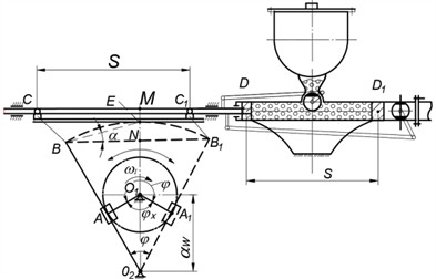
a) Kinematic diagram of a scotch-piston pump
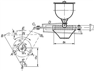
b) Kinematic diagram of a crank-scotch piston pump
The displacement of the piston in the pump hydraulic cylinder in the crank-link mechanism (Fig. 1(b)) is determined depending on the length of the crank radius:
where is the radius of the crank, 35 m substituting, we get 0.7 m.
The speed of movement of point of the crank of the main link of the rocker mechanism is determined by the formula:
where is the angular velocity of the crank rotation, rad/s, where is the crank rotation frequency, 60 rev/min, is the crank radius, 0.35 m, 3.14.
Substituting the numerical values into Eq. (6) we obtain:
Speed of movement points of the crank of the main link of the rocker mechanism (Fig. 1(b)) is determined by the formula , where is the angular velocity of rotation of point of the crank, 6.28 rad/s, here is the rotation frequency of the crank, 60 rev/min, 3.14, rad/s.
Substituting numerical values into the Eq. (7) we get: 6.28 rad/s, 2.2 m/s.
From Fig. 1(a), we determine the maximum angular velocity of the B-link peak. Thus, during horizontal movement, … will be in the same vertical position of the mechanism as point of slider 11 of crank 12 and coincide with the vertical level at point . From the relationship, we obtain, where the angle is the angle of inclination between and , 0.1736 rad, :
Then, the maximum speed of point of the link 10 in the working area is determined at the junction of the horizontal and vertical movements of the two lines at point :
Substituting the numerical values into Eq. (9), we obtain the calculated value of the maximum speed of the top of point of the slide, 2.37 m/s accordingly, the maximum speed the pump piston will be equal 2.37 m/s.
The maximum angular velocity of the link in the idle zone of the piston pump will be :
Also, the maximum speed points of the linkage and the pump piston in idle mode will be:
Substituting the numerical values into Eq. (11) we obtain 5.9 m/s.
We select the kinematic diagram for the displacement of point () of the slider (piston) (Fig. 2(a)) in the following scales: the distance of the piston travel length 0.01 m/mm, the angle of rotation of the crank and time: 0.0067 s/mm, where is the angular velocity of the crank, 6.28 rad/s, is the time of one revolution of the crank, 0.0014 s, and is the length of the segment along the abscissa coordinate axis, we take 150 mm, substituting the numerical values, we get: 0.0067 s/mm; 6.28/150 = 0.042 rad/mm.
One turn divide the crank’s circumference into 12 parts and transfer them to the diagram along the abscissa axis of a flat coordinate system, and equate this segment to an angle of , where one division is equal to 30°. Here, one position of the interval, for example, from the 0 to 2 mark, is equal to the crank rotation angle 60°. Along the ordinate of the diagram, we plot the displacement of the piston stroke from point to point , the maximum interval is equal to 1.25 m. The diagram shows asymmetrical phase angles of the working stroke 8 and the idle stroke of the piston 4: = 240°, = 120°.
To determine the speed and to calculate the piston link acceleration, we first differentiated the diagram, then the diagram. The velocity scaling factor of the diagram (Fig. 2(b)) is, where is the pole distance, 25 mm; substituting, we obtain. We construct the acceleration diagram (Fig. 2(c)) by graphically differentiating the diagram with respect to time . The acceleration scaling factor is, where is the pole distance, 8 mm; substituting the numerical values, we obtain. The numerical values obtained for the piston link position points are summarized in Table 1: , 0.06 m/s, , 0.891 m/s2.
Maximum piston speed the obtained values of the piston-rocker pump in the working zone were in position 5 (Fig. 2(b)) 2.51 m/s, and in the idle zone 5.1 m/s, and the piston acceleration in position 5 was 35.64 m/s2 and in position 12 of idle running 50.78 m/s2. Also, the maximum piston speed of the crank-rocker pump was: 2.05 m/s and 2.1 m/s, and the maximum acceleration in position 9 was 16.04 m/s2 and in position 12 of idle running 16.93 m/s2.
Table 1Numerical values of the travel distance SD, speed VD and acceleration αD of the pump piston
No. p/p | , mm | , m/s | , m/s2 | , mm | , mm | , m/s2 |
O(12) | 0 | 2.16 | 24.95 | 0 | 0.24 | 17.82 |
1 | 0.09 | 0.96 | 17.47 | 0.03 | 0.48 | 5,346 |
2 | 0.25 | 4.8 | 4,455 | 0.11 | 1.02 | 2,228 |
3 | 0.44 | 2.2 | 0.891 | 0.29 | 1.38 | 0.445 |
4 | 0.63 | 2.46 | –1,337 | 0.43 | 4.8 | –1,782 |
5 | 0.84 | 2.51 | –4,455 | 0.61 | 2.05 | –8,829 |
6 | 1.02 | 2.16 | –6,237 | 0.7 | 1.5 | –12.47 |
7 | 1.18 | 1.68 | –9.81 | 0.72 | 0.18 | –14.26 |
8 | 1.25 | 1.14 | –26.73 | 0.62 | 1.02 | –16.04 |
9 | 1.08 | 2.4 | –35.64 | 0.41 | 2.1 | 1,782 |
10 | 0.63 | 5.6 | 5,346 | 0.22 | 1.2 | 12.47 |
11 | 0.17 | 2.28 | 50,767 | 0.05 | 0.54 | 16.93 |
Fig. 2Kinematic diagram of the piston of a spool-piston pump: 1 – kinematic diagram of a scotch-piston pump, 2 – kinematic diagram of a crank-scotch piston pump
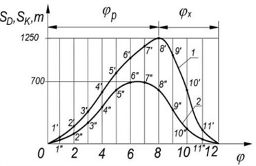
a) The displacement of the piston stroke
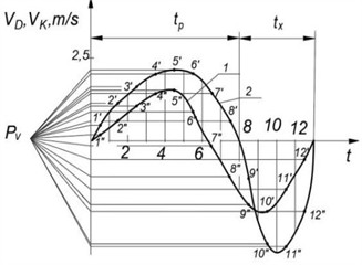
b) The linear velocity of the piston

c) The acceleration of the piston
The percentage difference in maximum speeds was obtained. In the parameters of the pump piston, by comparing theoretical calculations with the obtained results of the numerical values of the kinematic diagrams (Fig. 2(b)) for the rocker-piston mechanism:
– For the working stroke of the piston:
– For idle stroke of the piston:
4. Conclusions
The kinematic diagram of a rocker-piston pump was investigated, in which asymmetric phase angles of the working and idle strokes of the rocker mechanism crank were identified, which led to an increase in the length of the working stroke of the piston by several times than that of serial pumps, which leads to an increase in the pump performance 240° 120°.
Based on the constructed kinematic diagrams, their maximum speeds in the working zone and in the idle zone were obtained 2.51 m/s; 5.6 m/s.
Reducing the piston speed in the pump’s hydraulic cylinder helps reduce piston wear and abrasion of the hydraulic pump surface. Also, reducing the average speed in the piston's working stroke reduces the electric motor's power consumption.
5. Future possibilities
In future studies, the graph-analytical model could be extended to include dynamic forces, friction, and elastic deformations to more fully simulate real-world conditions.
Refining the choice of asymmetric phase angles ( and ) through computational optimization can improve the balance between performance and energy efficiency.
The implementation of sensors and microcontrollers for adaptive crankshaft control can provide intelligent adjustment of piston movement depending on load and flow.
Creating a digital twin of a pumping mechanism will enable remote monitoring, fault prediction, and performance optimization using real-time data.
The rocker-piston concept can be tested and adapted for high pressure applications such as oil production or chemical injection systems.
Further research will allow us to analyze the impact of reducing piston speed on energy consumption, which will potentially allow us to implement new energy-saving operating modes.
The creation of a physical prototype based on the proposed model will allow for experimental confirmation of the calculated kinematic parameters and wear characteristics.
The use of wear-resistant coatings or advanced composite materials on piston and cylinder components can extend service life and reduce maintenance.
References
-
B. Alimov, R. Sindarov, P. Egamshukurov, F. Dzhumabayeva, and S. Saidova, “Coulisse mechanism with rotating link for operating part drive unit of the mortar pump,” in E3S Web of Conferences, Vol. 264, p. 05050, Jun. 2021, https://doi.org/10.1051/e3sconf/202126405050
-
B. M. Alimov, R. U. Sindarov, P. S. Egamshukurov, and D. B. Alimova, “Epi and hypocyclic planetary gear to drive the working organ of the mixer,” in International Conference on Actual Problems of Applied Mechanics – APAM-2021, Vol. 2637, p. 060010, Jan. 2022, https://doi.org/10.1063/5.0120095
-
M. Imamovic, F. Hadžikadunić, A. Talić-Čikmiš, and A. Bošnjak, “Examples of kinematic analysis of complex mechanism using modern software applications,” in IOP Conference Series: Materials Science and Engineering, Vol. 659, No. 1, p. 012019, Oct. 2019, https://doi.org/10.1088/1757-899x/659/1/012019
-
E. Pennestri and P. P. Valentini, “A review of simple analytical methods for the kinematic synthesis of four-bar and slider-crank function generators for two and three prescribed finite positions,” Buletin Stiintific Seria Mecanica Aplicata, pp. 128–143, 2009.
-
S. Dange, S. Sant, A. Sali, P. Pethodam, and S. Belgamwar, “Design and analysis of planetary gearbox for industrial concrete mixer,” International Journal of Latest Research in Engineering and Technology (IJLRET), Vol. 2, No. 4, pp. 41–45, Apr. 2016.
-
R. A. Vetal, S. S. Gawade, “Development of gear box for submersible mixer,” International Journal of Engineering Applied Sciences and Technology (IJEAST), Vol. 5, No. 6, pp. 2455–2143, Oct. 2020.
-
A. B. A. Sakarya and L. W. Mays, “Optimal operation of water distribution pumps considering water quality,” Journal of Water Resources Planning and Management, Vol. 126, No. 4, pp. 210–220, Jul. 2000, https://doi.org/10.1061/(asce)0733-9496(2000)126:4(210)
-
P. F. Boulos, B. W. Karney, D. J. Wood, and S. Lingireddy, “Hydraulic transient guidelines for protecting water distribution systems,” Journal AWWA, Vol. 97, No. 5, pp. 111–124, May 2005, https://doi.org/10.1002/j.1551-8833.2005.tb10892.x
About this article

The authors have not disclosed any funding.
The datasets generated during and/or analyzed during the current study are available from the corresponding author on reasonable request.
The authors declare that they have no conflict of interest.
