Abstract
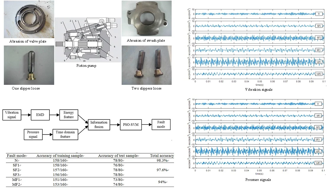
Piston pumps are key components in construction machinery, the failure of which may cause long delay of the construction work and even lead to serious accident. Because construction machines are exposed to poor working conditions, multiple faults of piston pumps are most likely to occur simultaneously. When multiple faults occur together, it is difficult to detect. A multi-fault diagnosis method for piston pump based on information fusion and PSO-SVM is proposed in this thesis. Information fusion is used as fault feature extraction and PSO-SVM is applied as the fault mode classifier. According to the method, vibration signal and pressure signal of piston pump in normal state, single fault state and multi-fault state are collected at first. Then the empirical mode decomposition (EMD) is used to decompose vibration signals into different frequency band and energy features are extracted. These energy features extracted from vibration signals and time-domain features extracted from pressure signal are information fused at the feature layer and constitute the eigenvectors. Finally, these eigenvectors are put into support vector machine (SVM) and the working conditions of piston pump were classified. Particle swarm optimization (PSO) is applied to optimize two parameters of SVM. The experimental results show that the recognition accuracy of the normal state, three single failure modes and multi-fault modes are 98.3 %, 97.6 % and 94 % respectively. These recognition accuracies are higher than which using vibration signal or pressure signal alone. So, the proposed method can not only identify the single fault, but also effectively identify the multi-fault of piston pump.
Highlights
- A multi-fault diagnosis method for piston pump in construction machinery based on information fusion and PSO-SVM is proposed.
- Empirical mode decomposition (EMD) is used to decompose vibration signals into different frequency band and energy features are extracted.
- Particle swarm optimization (PSO) is applied to optimize two parameters of SVM as fault classifier.
- The experimental results show that the proposed method can not only identify the single fault, but also effectively identify the multi-fault of piston pump.
1. Introduction
With the development of a new round of global infrastructure construction, the construction machinery industry is ushering in new growth. According to specialist forecasting and market research company Off-Highway Research [1], global construction equipment sales rose 28 % in 2017 to almost 895,000 units. It is predicting that global sales will grow 6 % (by units) in 2018, and reach more than a million units in 2022. However, the safety operation of construction machinery is very severe. This is because construction machines are prone to failure due to their harsh working environment and aggressive loading conditions, while lack of care and maintenance. The consequence of the failure of construction machines would be catastrophic. For example, the breakdown of a tower crane in China in 2000 caused the death of 3 and the injury of dozens [2]. This motivates the manufactures and end users of construction machinery to seek for appropriate way to look after their machines.
Hydraulic systems are widely applied in construction machines and other industries such as aerospace, automotive and agriculture. In general, most hydraulic systems require high reliability and the condition monitoring approach is most desirable [3]. As power source and key element in the hydraulic systems, piston pumps are widely used due to high working pressure, large flow and other advantages [4]. Because of poor working condition, high load and long running time, various failures often occur and lead to efficiency decline, pressure fluctuation, unexpected machine breakdowns, even worse, catastrophic consequences [5, 6]. Relevant statistics [7] showed that the hydraulic system failure accounts for about 60 % of the crane failures, of which nearly half were caused by the piston pumps. In the failure of the concrete pump truck, the failure rate of the hydraulic system was about 70 % and the piston pumps accounted for about 40 %. Therefore, it is of great significance to carry out the research on condition monitoring and fault diagnosis of piston pump.
For the piston pump, due to the complex structure, nonlinear relationship between internal variables and the liquid-solid coupling effect, the accurate mathematical model is very difficult to obtain. As a result, data-driven diagnosis methods are commonly used [8, 9]. Considering easy measurement and low cost, the pressure signal and vibration signal were usually observed for fault diagnosis of piston pump. On the one hand, pressure signal is one of the most important dynamic parameters which reveal the operating status of the piston pump [10-13]. Gao et al. [10] found that the discharge pressure was an informative variable of pump operation status and carried sufficient information to support a sensitive and reliable pump fault diagnosis. He proposed a wavelet analysis-based health diagnosis method to detect faults of hydraulic pumps with the information of pulsation discharge pressure. Based on pressure signal, Zhao et al. [11] proposed a method combining intermittent chaos with sliding window symbol sequence statistics to realize automatic real-time early fault diagnosis. Lu et al. [12] created an EEMD paving and optimized support vector regression method to detect faults and estimate the fault sizes of a piston pump based upon discharge pressure signals. On the other hand, vibration signal also reflects the performance of the piston pumps and the faults of piston pumps are generally accompanied by changes in vibration signal [14-18]. Jiang et al. [14] found the fault vibration signals of hydraulic pump were often modulated by the impact and the fault features were concealed when it became fault. Aiming at the feature extraction from the signals, they proposed a fusion method based on local mean decomposition and improved adaptive multi-scale morphology analysis. In order to extract degradation feature, Sun et al. [15] proposed a novel method based upon vibration signal using morphological un-decimated wavelet decomposition and discrete cosine transform. Based on vibration signal, Wang et al. [16] created a method using deep belief networks to detect five classes of commonly occurred faults of in piston pumps. An optimum intrinsic mode functions (IMFs) selection based envelope analysis was proposed by Du [17] to detect bearing failure in piston pump.
These above methods have been proven to be effective for piston pumps fault diagnosis. But most methods are based on the assumption that only single fault occur individually in piston pump at a given moment. However, as we know, construction machinery often works under very harsh conditions. Piston pumps probably have variety kinds of fault and multiple faults are most likely to occur simultaneously [19, 20]. When multiple faults occur together, the fault features will mix together, and any single diagnostic signal is imprecise and incomplete. Therefore, both pressure signal and vibration signal, that is to say information fusion should be used to detect multi-fault of piston pumps in construction machinery [21].
Furthermore, fault diagnosis generally is regarded as a pattern recognition problem. During the pattern recognition classifier, SVM solves the local extreme point problem and the dimensionality disaster problem well and has stronger generalization ability than neural network [22]. It is considered as the best solution for classification to small sample data and widely used in the fault diagnosis [23, 24]. But the SVM model has some inherent limitations. One of important limitation is before training the SVM model, penalty factor and kernel parameter should be predetermined, which has great impact on the classification accuracy. PSO optimization algorithm is applied to the parameter optimization of SVM. In the PSO method [25], the particles are “flying” in the solution space, remembering the individual optimal position and the global optimal position, and changing their positions and communicating to each other, until the optimal solution is found. It has been successfully applied to multi-dimensional optimization problem in SVM.
In this paper, a multi-fault diagnosis method for piston pump based on information fusion and PSO-SVM was proposed. At first, vibration signal and pressure signal of piston pump in normal state, single fault state and multi-fault state were collected. Then the vibration signals were decomposed into different frequency band using EMD and energy features extraction. These energy features and nine time domain features extracted from pressure signal were information fused at the feature layer and constitute the eigenvectors. Finally, these fault eigenvectors were input into PSO-SVM and the working conditions of piston pump were classified. The effectiveness of the proposed method in detecting the multi-fault of piston pump was verified by experimental research.
The remaining part of the paper is organized as follows. Structure of piston pump in the construction machines and fault mechanism were introduced in Section 2. In Section 3, the piston pump with normal state, 3 signal fault states and 2 multi-fault states were test. Section 4 was the fault feature extraction from vibration signal and pressure signal. In Section 5, PSO-SVM was introduced and used as pattern recognition classifier in the fault diagnosis of piston pump. The paper is concluded with a few key remarks in Section 6.
2. Structure of piston pump and fault mechanism analysis
2.1. Structure of piston pump in the construction machines
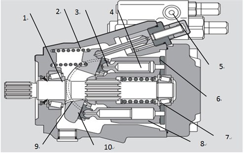
Piston pumps are not only rotating machines, but also reciprocating machines. They are designed to convert the rotary motion of the input shaft to the reciprocating motion of pistons. The typical structure diagram of piston pump in construction machines is shown in Fig. 1. The piston pump has 9 pistons installed in the piston holes which are evenly distributed along the cylinder block. The function of the compression spring is to keep the slipper contact with the swash plate and press the cylinder block against the valve plate. The tilt angle of the swash plate is controlled by the electromagnetic valve. The crescent bearing is used to adjust the tilt angle of the swash plate with the electromagnetic valve. The valve plate has two waist-shaped ports respectively connected with the suction and discharge ports of the piston pump. When the cylinder block is rotated by the drive shaft, the pistons reciprocate along the axis direction while rotating with the cylinder block. When the piston rotates from the upper side of the figure to the lower side, the slipper retracts with the swash plate and partial vacuum is formed in the piston hole. The hydraulic oil enters the piston hole from the oil suction port through the valve plate and the oil suction process has been completed. When the piston rotates to the upper side, the pressing force pushes the piston move to the right side. With the continuous reduction of volume of the piston hole, the hydraulic oil is discharged through the oil discharge port connected to the valve plate and the oil discharge process has been completed.
Fig. 1Structure diagram of the piston pump in construction machines: 1 – drive shaft, 2 – compression spring, 3 – slipper, 4 – piston, 5 – electromagnetic valve, 6 – valve plate, 7 – bearing, 8 – cylinder, 9 – crescent bearing, 10 – swash plate
2.2. Fault mechanism analysis of piston pump
As seen from section 2.1, there are four frictional pairs in the piston pump: valve plate/cylinder block, piston/piston bore, swash plate/slipper and piston head/slipper. Because of poor working condition, high load and long running time, wear in the pairs will become more and more serious. As a consequence, it will result in efficiency declining, pressure fluctuation, abnormal vibration, and shorten its service life. The common fault modes and mechanism analysis in the piston pumps are shown in Table 1 [25].
From Table 1, we can know majority of single fault can be identified by monitoring pressure signal or vibration signal. However, for the construction machines, which have to work in harsh environments over time. Multiple faults are most likely to happen simultaneously in the piston pump. For example, when solid contaminants the hydraulic oil, abrasion will occur not only in valve plate/cylinder block, but also in piston/piston bore. It increases the difficulty of fault diagnosis. Any single information is inaccurate and incomplete. Therefore, both pressure signal and vibration signal should be used for comprehensive evaluation.
Table 1Fault modes and mechanism analysis in the piston pump
Fault mode | Mechanism analysis | Effect |
Abrasion of swash plate | Assembly error, serious wear of gaskets on one side of swash plate, poor lubrication | Abnormal vibration |
Abrasion of valve plate | Solid contaminants in fluid, lubrication film is damaged, mixed lubrication | Leakage increase, pressure fluctuation and abnormal vibration |
Abrasion of piston | Solid contaminants in fluid, poor lubrication between piston and piston bore | Leakage increase, pressure fluctuation and abnormal vibration |
Slipper loose | Manufacturing and assembly error, repetitive loads on pistons, poor lubrication between piston and slipper | Abnormal vibration |
3. Experimental investigation
In order to investigate the multi-fault diagnosis for piston pump, the experiment was done on an experimental platform which was shown in Fig. 2.
Fig. 2Experimental platform
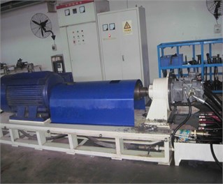
a) Layout of experimental platform
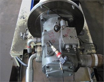
b) The test piston pump and sensor
This platform mainly composed of an AC motor, a gear reducer, a hydraulic control circuit, a piston pump and some measurement devices. The piston pump was driven by the AC motor and the gear reducer. The outlet of the piston pump connected a throttle valve and a relief valve, and finally linked to the tank. In this experiment, the load was imposed by the throttle valve, and relief valve kept safety. The type of the piston pump in this experiment was A11VLO190 which has 9 pistons and nominal pressure is 35 MPa. The accelerometer was mounted on the pump casing to collect vibration signal of axis direction. The pressure sensor was installed in the outlet of the piston pump to collect pressure signal. Data acquisition system included an industrial computer and a DEWETRON Instrument of DEWE-2521.
The faulty components were collected from construction machinery manufacturers and as shown in Fig. 3. Total 6 states (including normal state, 3 single fault states, and 3 multi-fault states) of piston pumps were tested, as shown in Table 2.
Fig. 3Faulty components
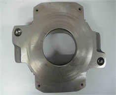
a) Abrasion of swash plate
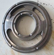
b) Abrasion of valve plate
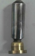
c) One slipper loose
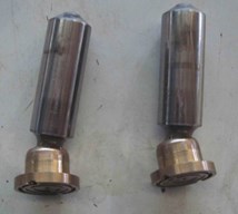
d) Two slippers loose
Table 2Fault mode in the experiment
Code | Mode |
N | Normal |
SF1 | Abrasion of swash plate |
SF2 | Abrasion of valve plate |
SF3 | One slipper loose |
MF1 | Two slippers loose |
MF2 | Abrasion of swash plate and valve plate |
In the experiment, the motor speed was set to 1600 r/min. So, the shaft frequency () and the pulse frequency () of oil supply can be calculated as:
where is the rotate speed and is the piston number.
In order to obtain enough fault samples, the load was adjusted to 5 MPa, 10 MPa, 15 MPa and 20 MPa respectively. Therefore, the piston pump was tested in 4 types of loads and 6 types of health conditions, and a total of 24 groups of operation data were obtained. For every test, the sampling frequency was set to 10 kHz and sampling time was 60 s. Each signal was divided into 60 segments, 40 of which were used as training samples and the other 20 were used as test samples in the fault diagnosis, as shown in Table 3.
Table 3Fault samples of piston pump
Fault mode | N | SF1 | SF2 | SF3 | MF1 | MF2 |
Training samples | 160 | 160 | 160 | 160 | 160 | 160 |
Test samples | 80 | 80 | 80 | 80 | 80 | 80 |
4. Fault feature extraction
4.1. Fault feature extraction from vibration signal
When the load pressure was 10 MPa, the time domain waveforms of the vibration signals of the test piston pump in 6 different states are shown in Fig. 4. As can be seen, all of the vibration signals exhibit obvious non-stationary characteristics. Different types of faults will cause different changes in the vibration signal. Most faults occur will result in increase of the amplitude of the vibration signal. Especially multi-fault, it will lead to more increase of the amplitude of the vibration signal. But it is difficult to judge the occurrence of different kinds of faults only by the vibration signals in time domain.
Fig. 4Time domain waveforms of vibration signals
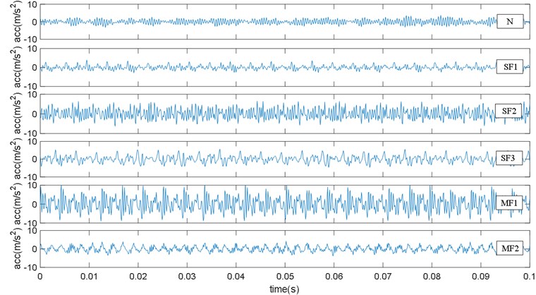
Fig. 5Frequency spectra of vibration signals
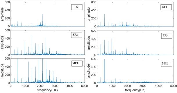
Frequency spectra are calculated by using the Fast Fourier Transforms (FFT) and the corresponding results are shown in Fig. 5. From Fig. 5, the pulse frequency, 240 Hz, is clearly observed from all frequency spectra in spite of the health state of the piston pump. Additionally, there are obvious peaks at the frequencies of ×240 Hz 1, 2, 3, …). However, the fault characteristic frequency is not obvious due to the additional vibration caused by faults was very weak relative to which caused by the rotation and the oil supply. Therefore, it was difficult to diagnose different faults of piston pump by the frequency spectra of vibration signals. Furthermore, it also can be seen from Fig. 5 that the faults will bring periodic impacts accompanying the operation of the piston pump. Different types of faults will change the energy of different frequency bands of the vibration signal, so the energy in different frequency bands of the vibration signal contains rich fault characteristics information.
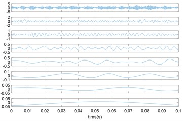
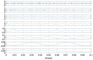
In order to obtain the energy characteristics in different frequency bands of the vibration signal, empirical mode decomposition (EMD) was used to decompose the vibration signals and the results were shown in Fig. 6.
Fig. 6EMD of vibration signals
a) N
b) SF1
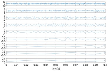
c) SF2
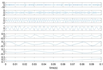
d) SF3
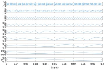
e) MF1
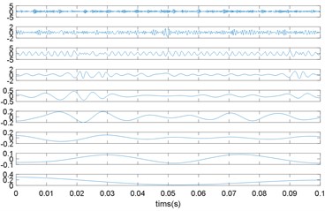
f) MF2
As we know, EMD can decompose the signal into a group of Intrinsic Mode Functions (IMFs), which contain components of original signal in different frequency bands from high frequency to low frequency [26]. It can be seen from Fig. 6 that vibration signals in different modes were decomposed into 8 to 9 IMFs. Each IMF was a stationary signal with a single component and the IMFs in same frequency band were obviously different under 6 different modes. Therefore, the energy variation of each frequency band implied the healthy state of the piston pump.
The steps for extracting the energy characteristics after EMD of vibration signals were as follows:
1) Calculate the total energy of each IMF:
where is IMF obtained after EMD.
2) Construct feature vectors :
3) Normalize the feature vector:
where
Using the above calculation method, it was found that the sum of the energy of the first six IMF components has reached more than 95 % of the total energy for each state. It is mean that the energy of vibration signal is mainly concentrated in the high-frequency band and the first 6 IMF components contained the main healthy state information of the piston pump. Therefore, the energy of the first 6 IMF components extracted from the vibration signal constitutes the feature vector for the fault diagnosis of piston pump.
4.2. Fault feature extraction from pressure signal
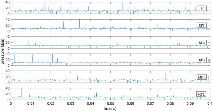
When the load pressure was 10 MPa, the time domain waveforms of the pressure signals of the test piston pump in 6 different states are shown in Fig. 7. It can be seen that pressure signals fluctuate around 10 MPa and there is a significant pressure pulsation every 0.04 s, which is consistent with the pulse frequency 240 Hz. When the piston pump has different types of faults, the time domain waveform of the pressure signal will change. Therefore, the 9 time domain characteristics parameters of the pressure signal constitute the feature vector for the fault diagnosis of piston pump. The selected 9 time domain characteristic parameters are defined as Table 4. In which is a signal series for 1, 2, …, , is the number of data points.
Fig. 7Pressure signals
5. Fault diagnosis
5.1. PSO-SVM classifier
In this study, Support Vector Machine (SVM) was selected as the classifier for fault diagnosis. SVM is a machine learning technique which based on statistical theory and structural risk minimization. It is widely used in the pattern recognition and fault diagnosis [28, 29].
Table 4Time-domain feature parameters
Feature | Equation |
Mean | |
Root mean square | |
Standard deviation | |
Skewness | |
Kurtosis | |
Crest factor | |
Latitude factor | |
Shape factor | |
Impulse factor |
However, before training the SVM model, penalty factor and kernel parameter should be predetermined, which has great impact on the classification accuracy. Using PSO algorithm particle swarm optimization (PSO) to optimize the two parameters of SVM, the steps are listed as follows.
Step 1. Initialize the penalty factor and the kernel parameter to build a SVM model.
Step 2. A two-dimensional particle swarm (, ) is established, in which the parameter is optimized by particle swarm and the parameter is optimized by particle swarm respectively. Setting the initial values of the particles (including the inertia weight , positive acceleration constants and , the constraint factor and the number of iterations) and generating the initial position and velocity of the particle swarm are randomly.
Step 3. The initial velocity and position are substituted into the SVM to obtain the fitness values of each particle, which is:
where denotes the fitness value of the th particle, is the number of samples. is the SVM output of the th sample of the th particle, and is the average output of all samples.
Step 4. For each particle, compare its fitness value to the best position it has experienced and use the best value as the current best position.
Step 5. For each particle, compare its fitness value to the best position experienced by the group and set the best value to the current position of the group.
Step 6. Adjust the velocity and position of the particles according to Eq. (7) and Eq. (8):
where, is a particle in the group and is the dimension of the particle. and represent the velocity and the position of particle in the -dimensional space respectively. denotes the individual optimal solution of particle and denotes the group optimal solution of all particles. is a constraint factor used to control the velocity weight, which is usually set to 1. is the inertia weight, which is used to balance the capabilities of global exploration and local exploitation. and are two positive acceleration constants regulating the relative velocities, and they are usually set to 2. and are random variables in the range [0,1].
Step 7. Check whether the end condition is met (the minimum error requirement or the maximum number of iterations is reached). And if it is yes, stop the iteration, or return to step3.
Step 8. The optimized parameters and are brought into the Equation to establish the SVM classification model.
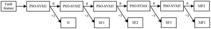
Furthermore, the original SVM is a typical two-class classifier. However, the fault diagnosis of piston pump in this paper needs a multi-classification to separate 6 modes. For a case of classes, -1 two-class SVM classifiers are needed. So, the diagnosis model which comprises five two-class SVM classifiers was build. With all training samples of the six modes, PSO-RVM1 was trained to separate the normal state from fault states. When the input fault feature was a sample representing normal state, the output was set to 1, otherwise the output was set to 0. PSO-SVM2, PSO-SVM3 and PSO-SVM4 were designed to separate 3 single fault states. PSO-SVM5 was designed to separate 2 multi-fault states. The diagnosis process of PSO-SVM classifiers was shown in Fig. 8.
Fig. 8Diagnosis process of PSO-SVM classifier
5.2. Fault diagnosis results
The diagnosis results of multi-source information fusion were compared with the results of vibration signal and pressure signal diagnosis alone.
The fault diagnosis process based on EMD energy feature of vibration signal and PSO-SVM was shown in Fig. 9 The fault diagnosis results are shown in Table 5. It can be seen that the recognition accuracy of the normal state and three single failure modes are 96.3 % and 92.4 % respectively. This shows that the energy characteristics extracted after EMD decomposition reflect the health status of the piston pump well. At the same time, PSO-SVM can also distinguish between the normal state and several single fault modes of piston pump. However, we also can see the recognition rate of the multi-fault is relatively low, which is 87.1 %. Therefore, relying on vibration signals to detect multi-fault does not achieve satisfactory result.
Fig. 9Fault diagnosis process based on vibration signal

The fault diagnosis process based on time domain feature of pressure signal and PSO-SVM was shown in Fig. 10. The fault diagnosis results are shown in Table 6. The recognition accuracy using pressure signal is lower than which based on vibration signal. Especially, the recognition accuracy for multi-fault is only 78.9 %. Therefore, it is necessary to carry out subsequent research on fault feature extraction method and fault pattern recognition method based on pressure signal.
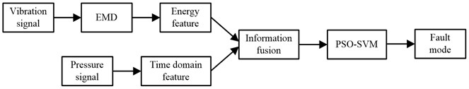
The fault diagnosis process based on multi-source information fusion and PSO-SVM was shown in Fig. 11. The fault diagnosis results are shown in Table 7. It can be seen that the recognition accuracy of the normal state, three single failure modes are 98.3 % and 97.6 % respectively. These recognition accuracies are higher than which using a single signal. Moreover, two multi-fault modes can be well recognized and the recognition accuracy reaches 94 %. Therefore, using the method proposed in this paper can not only identify the single fault, but also effectively identify multi-fault of the piston pump.
Table 5Fault diagnosis result of vibrational signal
Fault mode | Accuracy of training sample | Accuracy of test sample | Total accuracy |
N | 156/160 | 75/80 | 96.3 % |
SF1 | 150/160 | 71/80 | 92.4 % |
SF2 | 151/160 | 73/80 | |
SF3 | 148/160 | 72/80 | |
MF1 | 142/160 | 68/80 | 87.1 % |
MF2 | 139/160 | 69/80 |
Table 6Fault diagnosis result of pressure signal
Fault mode | Accuracy of training sample | Accuracy of test sample | Total accuracy |
N | 136/160 | 68/80 | 85 % |
SF1 | 134/160 | 66/80 | 82.6 % |
SF2 | 132/160 | 65/80 | |
SF3 | 131/160 | 67/80 | |
MF1 | 129/160 | 62/80 | 78.9 % |
MF2 | 126/160 | 62/80 |
Table 7Fault diagnosis result of information fusion
Fault mode | Accuracy of training sample | Accuracy of test sample | Total accuracy |
N | 158/160 | 78/80 | 98.3 % |
SF1 | 158/160 | 76/80 | 97.6 % |
SF2 | 157/160 | 78/80 | |
SF3 | 156/160 | 78/80 | |
MF1 | 151/160 | 73/80 | 94 % |
MF2 | 153/160 | 74/80 |
Fig. 10Fault diagnosis process based on pressure signal
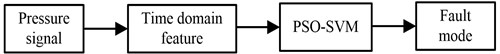
Fig. 11Fault diagnosis process based on multi-source information fusion
6. Conclusions
Construction machines are usually exposed to very harsh working environments, multiple faults of piston pumps are most likely to occur simultaneously. When multiple faults occur simultaneously, the fault features will be mixed together, and any single diagnostic signal is imprecise and incomplete. A novel multi-fault diagnosis method for piston pump based on information fusion and PSO-SVM is proposed and experimental research was done in this thesis.
1) According to the method, vibration signal and pressure signal of piston pump were collected at first. Then the vibration signals were decomposed into different frequency band using EMD and energy features were extracted. These energy features and nine time domain features extracted from pressure signal were information fused at the feature layer and constitute the eigenvectors. Finally, these eigenvectors were put into SVM and the working conditions of piston pump are classified.
2) The experimental results show that the recognition accuracy of the normal state, three single faults and two multi-fault modes are 98.3 %, 97.6 % and 94 % respectively. The recognition accuracies are higher than which using vibration signal or pressure signal alone. Therefore, the proposed method can effectively identify multi-fault of the piston pump.
References
-
Global Demand for Construction Machinery on the Rise. the Construction Index, https://www.theconstructionindex.co.uk/news/view/global-demand-for-construction-machinery-on-the-rise.
-
People’s Daily, Inc., http://www.people.com.cn/GB/channel4/27/20000929/255095.html.
-
Zhou R. S., Jiao Z. X., Wang S. P. Current research and developing trends on fault diagnosis of hydraulic systems. Journal of Mechanical Engineering, Vol. 42, Issue 9, 2006, p. 6-14.
-
Cho I. S. A study on the optimum design for the valve plate of a swash plate-type oil hydraulic piston pump. Journal of Mechanical Science and Technology, Vol. 29, Issue 6, 2015, p. 2409-2413.
-
Oh J. K., Moon H. B., Cho H. Theoretical study on performance characteristics of a variable displacement vane pump according to a variable amount occurrence. Journal of Mechanical Science and Technology, Vol. 29, Issue 9, 2015, p. 3717-3726.
-
Ma J. M., Chen J., Li J. Wear analysis of swash plate/slipper pair of axis piston hydraulic pump. Tribology International, Vol. 90, 2015, p. 467-472.
-
Tang H. B. Research on Key Technology of Fault Diagnosis for Pumping Hydraulic System of Concrete Pump Truck. Ph.D. Thesis, Central South University, 2012, (in Chinese).
-
Hast D., Findeisen R., St Streif Detection and isolation of parametric faults in hydraulic pumps using a set-based approach and quantitative-qualitative fault specifications. Control Engineering Practice, Vol. 40, 2015, p. 61-70.
-
Zhao W. L., Wang Z. L., Ma J. Fault diagnosis of a hydraulic pump based on the CEEMD-STFT time-frequency entropy method and multiclass SVM classifier. Shock and Vibration, Vol. 2016, 2016, p. 2609856.
-
Gao Y. J., Zhang Q. wavelet packet and residual analysis based method for hydraulic pump health diagnosis. Proceedings of the Institution of Mechanical Engineers, Part D: Journal of Automobile Engineering, Vol. 220, Issue 6, 2006, p. 735-745.
-
Zhao Z., Jia M., Wang M., Wang S. Intermittent chaos and sliding window symbol sequence statistics-based early fault diagnosis for hydraulic pump on hydraulic tube tester. Mechanical System and Signal Processing, Vol. 23, 2009, p. 1573-1585.
-
Lu C. Q., Wang S. P., Makis V. Fault severity recognition of aviation piston pump based on feature extraction of EEMD paving and optimized support vector regression model. Aerospace Science and Technology, Vol. 67, 2017, p. 105-117.
-
Lu C. Q., Wang S. P., Zhang C. Fault diagnosis of hydraulic piston pumps based on a two-step EMD method and fuzzy C-means clustering. Proceedings of the Institution of Mechanical Engineers, Part C: Journal of Mechanical Engineering Science, Vol. 230, Issue 16, 2016, p. 2913-2928.
-
Jiang W. L., Zheng Z., Zhu Y., Li Y. Demodulation for hydraulic pump fault signals based on local mean decomposition and improved adaptive multiscale morphology analysis. Mechanical Systems and Signal Processing, Vol. 58, Issue 59, 2015, p. 179-205.
-
Sun J., Li H. R., Xu B. H. The morphological undecimated wavelet decomposition – discrete cosine transform composite spectrum fusion algorithm and its application on hydraulic pumps. Measurement, Vol. 94, 2016, p. 794-805.
-
Wang S. H., Xiang J. W., Zhong Y. T. A data indicator-based deep belief networks to detect multiple faults in axial piston pumps. Mechanical Systems and Signal Processing, Vol. 112, 2018, p. 154-170.
-
Du W. L., Wang Z. Y., Gong X. Y. Optimum IMFs selection based envelope analysis of bearing fault diagnosis in plunger pump. Shock and Vibration, Vol. 2016, 2016, p. 1248626.
-
Du W. L., Sh Li A., Ye P. F. Fault diagnosis of plunger pump in truck crane based on relevance vector machine with particle swarm optimization algorithm. Shock and Vibration, Vol. 20, Issue 4, 2013, p. 781-792.
-
Du J., Wang S. P., Zhang H. Y. Layered clustering multi-fault diagnosis for hydraulic piston pump. Mechanical Systems and Signal Processing, Vol. 36, 2013, p. 487-504.
-
Lu C. Q., Wang S. P., Wang X. J. A multi-source information fusion fault diagnosis for aviation hydraulic pump based on the new evidence similarity distance. Aerospace Science and Technology, Vol. 71, 2017, p. 392-401.
-
Gao Q., Sh Tang H., Xiang J. W. A multi-sensor fault detection strategy for axial piston pump using the Walsh transform method. International Journal of Distributed Sensor Networks, Vol. 14, Issue 4, 2018, https://doi.org/10.1177/1550147718772531.
-
Vapnik V. N., Golowich S., Smola A. Support vector method for function approximation, regression simulation and signal processing. Proceedings of the 9th International Conference on Neural Information Processing Systems, 1996, p. 281-287.
-
Widodo A., Yang B. S. Support vector machine condition monitoring and fault diagnosis. Mechanical System and Signal Processing, Vol. 21, 2007, p. 2560-2574.
-
Malek A., Nuannuan Z., Melvin A. Multidimensional pattern recognition and classification of white blood cells using support vector machines. Particle and Particle Systems Characterization, Vol. 22, Issue 2, 2005, p. 107-118.
-
Kennedy J., Eberhnrt R. C. Particle swarm optimization. Proceedings of International Conference on Neural Networks, 1995.
-
Lázaro J. G. M., Pinilla C. B., Prada S. R. A Survey of approaches for fault diagnosis in axial piston pumps. Proceedings of the International Mechanical Engineering Congress and Exposition, 2016.
-
Huang N. E., Shen Z., et al. The empirical mode decomposition and the Hilbert spectrum for nonlinear and non-stationary time series analysis. Proceedings of the Royal Society of London. Series A, Mathematical and Physical Sciences, Vol. 454, 1998, p. 903-995.
-
Deng W., Yao R., Zhao H. M., et al. A novel intelligent diagnosis method using optimal LS-SVM with improved PSO algorithm. Soft Computing, Vol. 23, 2019, p. 2445-2462.
-
Deng W., Xu J. J., Zhao H. M. An improved ant colony optimization algorithm based on hybrid strategies for scheduling problem. IEEE Access, Vol. 7, 2019, p. 20281-20292.
Cited by
About this article

The work was supported by the National Natural Science Foundation of China (11402036) and Scientific Research Fund of Hunan Provincial Education Department (18B151).
