Abstract
This study presents a numerical investigation of the stress-strain state of the R65 rail and reinforced concrete sleeper using the finite element method. Three-dimensional finite element simulations were performed in the ABAQUS environment. Fatigue life assessment was subsequently carried out using the nCode DesignLife software, and corresponding S-N curves were constructed. The obtained results indicate that the predicted service life of the rail is approximately 770 million tons of accumulated gross traffic, while the reinforced concrete sleeper operates within the infinite fatigue life region of concrete. The developed approach makes it possible to predict the durability of railway track superstructure elements and to support optimization of maintenance planning.
Highlights
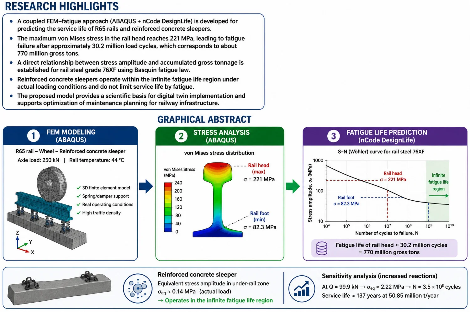
- A coupled FEM–fatigue approach (ABAQUS + nCode DesignLife) is developed for predicting rail and sleeper life.
- Maximum stress in the rail head reaches 221 MPa, leading to fatigue failure at about 30.2 million cycles.
- The predicted rail service life is approximately 770 million tons of accumulated gross traffic.
- Reinforced concrete sleepers operate within the infinite fatigue life region under actual loading conditions.
- The model supports digital twin applications and optimization of railway maintenance planning.
1. Introduction
The rapid development of railway transport systems is accompanied by a steady increase in axle loads, traffic density, and operating speeds. These factors significantly intensify the mechanical impact on track superstructure components, particularly rails and reinforced concrete sleepers, thereby increasing the likelihood of fatigue-related damage and structural degradation [1–3]. Fatigue failure remains one of the primary mechanisms limiting the service life of rails. Numerous studies have investigated fatigue behavior of metallic materials and the applicability of Basquin-Manson-Coffin type relationships for predicting durability under cyclic loading conditions [5]. In railway engineering, considerable attention has been devoted to stress analysis of rails, accumulation of residual deformations, and prediction of degradation processes in track components [6-7]. Classical investigations of track-rolling stock interaction [9], as well as more recent studies of wheel–rail contact behavior [10-11], have demonstrated that the highest stress levels occur in the rail head and rail foot zones. These regions are characterized by stress concentration and are therefore critical in the initiation and propagation of contact and bending fatigue cracks. In recent years, predictive modeling approaches for railway infrastructure assessment have gained increasing importance, including the application of numerical simulation methods and elements of digital twin concepts [8, 11]. The finite element method has proven to be an effective tool for evaluating the stress-strain state of track components under operational loading conditions [12]. Compared with traditional empirical life estimation approaches, finite element modeling enables more accurate identification of critical stress zones and supports the transition toward physics-based service life prediction. However, most existing methodologies for rail service life estimation remain based on generalized empirical relationships and do not fully account for region-specific operational conditions, such as increased axle loads, elevated rail temperatures, and high traffic density typical for the railways of the Republic of Uzbekistan. Furthermore, relatively few studies provide an integrated numerical framework that directly links finite element stress analysis with fatigue life prediction and conversion into accumulated gross tonnage, which limits practical implementation of predictive models in railway asset management systems. Therefore, the objective of this study is to develop a regionally adapted numerical model for forecasting the service life of R65 rails and reinforced concrete sleepers under actual operating conditions. The proposed approach is based on three-dimensional finite element modeling of the stress-strain state followed by fatigue analysis using S-N curves, enabling quantitative assessment of durability in terms of load cycles and accumulated gross tonnage.
2. Novelty and scientific contribution
The scientific novelty and practical contribution of this study consist of the following:
1) Integrated thermo-mechanical fatigue modelling framework. A coupled numerical approach combining three-dimensional finite element analysis (ABAQUS) with fatigue life prediction (nCode DesignLife) was developed for simultaneous assessment of rails and reinforced concrete sleepers within a unified computational environment.
2) Regional adaptation to Uzbekistan operating conditions. Unlike existing studies based on generalized loading scenarios, the model incorporates actual axle loads (250 kH), elevated rail temperature (44 °C), and high traffic intensity characteristic of main railway lines in Uzbekistan. This ensures region-specific reliability of service life prediction.
3) Direct conversion of stress amplitude to gross tonnage. A quantitative relationship between cyclic stress amplitude (221 MPa in the rail head) and accumulated gross tonnage (770 million tons) was established using Basquin fatigue law parameters for rail steel grade 76XF. This provides an engineering bridge between numerical modelling results and practical indicators.
4) Fatigue-based verification of sleeper durability. A sensitivity analysis of reinforced concrete sleeper performance under increasing reaction forces was performed. The results demonstrate that under current loading conditions, sleepers operate within the infinite fatigue life region, and their service life is governed by non-fatigue degradation mechanisms.
5) Foundation for digital twin implementation. The developed methodology forms the basis for creating a predictive digital framework for railway track asset management and may be integrated into digital twin systems for infrastructure monitoring and maintenance optimization.
3. Materials and methods
Each material possesses specific mechanical properties that must be considered in numerical modelling to ensure the accuracy and reliability of the obtained results. The ABAQUS finite element environment allows these material properties and boundary conditions to be incorporated directly into the numerical model. The numerical model included the following railway track components.
Table 1Track components, used during modeling
Track components | Density (kg/m2) | Young modulus () | Poisson’s ration () |
Rail (steel) | 7850 | 210 GPa | 0,3 |
Sleeper (concrete) | 1200 | 80 GPa | 0,3 |
To model the interaction between the bottom part of the rail and the sleeper, spring/damper elements were used. Such elements are widely used in numerical modelling to represent the elastic and damping behavior of track support systems. As they allow for effective consideration of both dynamic and static behavior of structural components.
The following characteristics of the spring/damper elements were applied:
– Spring stiffness – 78 kH/mm.
– Dashpot coefficient – 50 kH/m.
Table 2The information on the type and the number of elements and nodes in the modeled track components
Instance name | Element type | Elements | Nodes |
Rail | 2752 | 3652 | |
C3D8R | 2537 | ||
C3D6 | 215 | ||
Wheel | 1242 | 1788 | |
C3D8R | 1242 | ||
Sleeper | 5208 | 7693 | |
C3D8R | 5208 | ||
TOTAL | 9202 | 13133 |
Numerical loading process and boundary conditions:
1) The bottom surface of the sleeper is fixed — fully constrained at the ends (U1 = U2 = U3 = UR1 = UR2 = UR3 = 0).
2) The rail is constrained in selected translational and rotational degrees of freedom (U1 = UR3 = 0, U2 = U3 = UR1 = UR2 ≠ 0 remain free).
3) A displacement of two meters is applied to the wheel along the longitudinal direction (U2 ≠ 0), while its remaining translational and rotational degrees of freedom are locked (U1 = U3 = UR1 = UR2 = UR3 = 0, U2 ≠ 0).
The term “boundary conditions” encompasses all additional constraints that may be required to fully define a specific numerical problem. In the present modeling, the following boundary conditions were applied to the track structure:
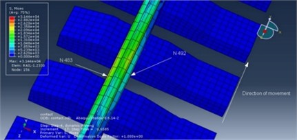
Calculations show that the maximum von Mises stress for increment No. 17 corresponds to node N483 (rail head), while the minimum von Mises stress for the same increment corresponds to node N492 (rail foot). The distribution of von Mises stresses is illustrated in Fig. 1–2. The stresses are 21.3×10³ N/cm2 (213 MPa) for node N483 and 8.23×10³ N/cm2 (82.3 MPa) for node N492. However, node N483 reaches the maximum stress value at time 0.7585 s, equal to 22.9×10³ N/cm (229 MPa) [13-15].
Fatigue life – S-N curve – Wöhler curve (for rail).
In materials science, fatigue is the weakening of a material caused by cyclic loading, resulting in progressive, brittle, and localized damage to the structure. Once a crack initiates, each loading cycle results in a slight increase in crack size, even if the repeated alternating or cyclic stresses are significantly below the normal strength. Stresses can be generated by vibration or thermal cycling [15]. Fatigue occurs due to:
– Simultaneous action of cyclic stress.
– Tensile stress (both directly applied and residual).
– Plastic deformation.
Fig. 1von Mises stress distribution
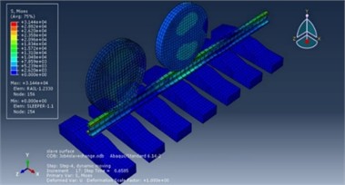
Fig. 2Location of nodes with maximum and minimum von Mises stress
A fatigue crack will not form or propagate unless at least one of these three factors is present. Most engineering failures are caused by fatigue.
The simulation results indicate that the stress amplitude in the rail head reaches 221 MPa, and in the rail base 82.3 MPa [16].
Fatigue life was estimated on the basis of finite element results obtained in ABAQUS and subsequent analysis performed in nCode DesignLife. The SN dependence can generally be expressed by Baskin’s fatigue law, which is defined as follows:
where – number of cycles before failure; – stress amplitude (221 MPa); – fatigue strength coefficient (1200 MPa for steel grade 76XF); – fatigue ductility coefficient (0.45); – fatigue strength index (0.0904 for steel grade 76XF):
4. Results and discussion
The obtained stress level in the rail head leads to fatigue failure after approximately 30.2 million axle passages, which is close to the standard at 770 million gross tons/km. The rail foot stress (at 82.3 MPa) does not limit the service life – the stresses are below the fatigue limit [17].
The conventional S-N curve (on a logarithmic scale) demonstrating the relationship between the stress amplitude and the number of cycles to failure is shown in Fig. 3. The stress levels at the rail head and foot, and the corresponding design cycles, are indicated.
Fig. 3Graph of stress amplitude (S) on the ordinate axis and the number of cycles to failure (N) on the logarithmic abscissa axis
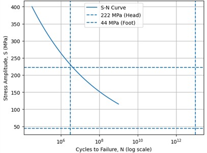
The analysis shows that most elements of the track superstructure operate within the infinite fatigue life region. The exception is the wheel-rail contact zone, which experiences a stress singularity, and assessing the durability in this zone is incorrect. For this zone, under a 250 kH load, the number of cycles before failure was approximately 30.2 million cycles (770 million gross tons), while for the rail foot, it ranged from [unclear] to infinity 3.23×10⁹ [18-19].
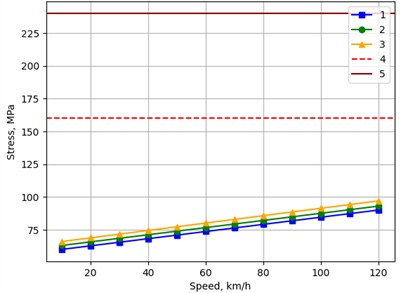
The maximum stresses at the rail-foot edges, which are the key parameter determining rail strength and are caused by the combined effect of vertical and lateral loads, as well as the moments generated by lateral forces and by the wheel-rail contact point shift on the rail head [20], are calculated according to the methodology as follows:
where, is the conversion factor from axial stresses in the rail foot to edge stresses; is the maximum stress in the rail foot caused by bending under the action of moment .
Fig. 4Relationship between the maximum stresses occurring at the rail-foot edges and train speed for different axle loads on straight track sections: 1 – 23.5 tf; 2 – 25 tf; 3 – 27 tf; 4 – allowable value according to the Methodology; 5 – allowable value according to GOST R 55050-2012
Based on finite element modeling, the stress-strain state of the R65 rail laid on reinforced concrete sleepers was determined under an axial load of 250 kH and a rail temperature of 44 °C. The section's traffic density is classified as high. Calculations have shown that the ultimate fatigue strength of the metal is reached after a gross load of 770 million tons [13].
5. Analysis of the results of modeling the service life of reinforced concrete sleepers
In materials science, concrete fatigue is the process of damage accumulation under cyclic loading, leading to the formation and development of cracks in the most stressed areas of the structure. For reinforced concrete sleepers, the critical zone is the subrail zone, where maximum bending and contact stresses occur [21-23].
The fatigue behaviour of the reinforced concrete sleeper was evaluated using finite element modelling in ABAQUS followed by fatigue analysis in nCode DesignLife. The model considered reactions at 14 nodes along the bottom surface of the rail, located on two adjacent sleepers. The highest reaction forces were observed at the central nodes of the sleeper support zone N2 and N2' [24-26]: 0.519×10³ H, 0.389×10³ H.
The average reaction to the node was:
Total reaction per sleeper at 14 nodes: 6.356 kH.
To convert reactions into equivalent stresses, the dependence obtained in the reference calculation was used:
where 2.53 MPa is the stress amplitude in the under-rail zone with a total reaction of 114 kH.
Thus, the equivalent voltage amplitude was: 0.02219×6.356 ≈ 0.14 MPa.
This value is significantly lower than the fatigue limit of concrete, which indicates a virtually unlimited service life of the sleeper according to the fatigue criterion under current operating conditions and loads [27-29].
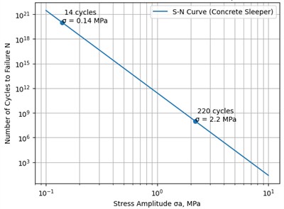
For sensitivity analysis, a calculation was performed for scenarios with a larger number of nodes (50, 100, 220), which is equivalent to an increase in the overall reaction. At 99.9 kH, 2.22 MPa was obtained, yielding a final number of cycles to failure of approximately 3.5×10⁸. With a traffic intensity of 50.85 million t/year (≈2.54 million axles/year), this corresponds to a service life of approximately 137 years.
A conventional S-N curve (logarithmic scale) plotted for a concrete sleeper. The graph shows the stress levels corresponding to the calculated scenarios and demonstrates that under actual load, the sleeper operates in the region of an infinite number of cycles in Fig. 4 [30-31].
Fig. 5S-N curve for a reinforced concrete sleeper with design stress levels indicated
6. Conclusions
Using finite element modeling in the ABAQUS/CAE environment, the stress-strain state of a type R65 rail was determined under an axial load of 250 kH and a temperature of 44 °C. It was found that the maximum von Mises stress occurs at the rail head ( 221 MPa), and the minimum at the rail foot ( 82.3 MPa).
A fatigue analysis conducted in nCode DesignLife showed that the rail head has a limited service life of approximately 30.2 million load cycles, equivalent to 770 million gross tons. This figure is consistent with the standard service life.
At a stress level of 82.3 MPa, the rail base is in the infinite service life zone, as the stress is below the material's fatigue limit. Consequently, the rail head in the wheel-rail contact zone is the limiting factor in service life.
The calculations demonstrate that under actual loading conditions the equivalent stress amplitude in the sub-rail zone does not exceed 0.14 MPa. This indicates a virtually unlimited fatigue life for the sleeper under existing operating conditions.
A sensitivity analysis to increasing loads showed that even with an increase in response to 99.9 kH, the stress amplitude only reaches 2.22 MPa, which corresponds to a service life of approximately 3.5×10⁸ cycles (~137 years at a traffic intensity of 50.85 million t/year).
Calculations have shown that, under current loads and traffic intensity, reinforced concrete sleepers operate within the concrete’s fatigue lifespan, and fatigue failure does not limit their service life. Sleeper service life is determined primarily by other factors, such as wear under the track deck, damage to fasteners, and ballast degradation.
References
-
V. S. Erasov and E. I. Oreshko, “Fatigue testing of metallic materials (Review), Part 2: analysis of the basquin-manson-coffin equation. Testing methodologies and data processing,” (in Russian), Aviation Materials and Technologies, Vol. 62, No. 1, 2021.
-
M. A. Bubnov, S. I. Dubinskiy, and E. E. Krasnovskiy, “Peculiarities of lifetime prediction of track structure fastenings with application of numerical modelling,” Theoretical and Applied Science, Vol. 67, No. 11, pp. 137–146, Nov. 2018, https://doi.org/10.15863/tas.2018.11.67.22
-
E. I. Konovalova and A. A. Podshivalova, “Determination of stresses at the edges of the rail foot under rolling stock impact,” (in Russian), Young Science of Siberia: Electronic Scientific Journal, Vol. 11, No. 1, 2021.
-
A. V. Andreev, V. P. Beltyukov, A. V. Sennikova, I. A. Simonyuk, and A. A. Tretyakov, “Improvement of the method for predicting the development of residual deformations of the railway track superstructure,” (in Russian), Proceedings of Petersburg Transport University, Vol. 41, No. 4, 2014.
-
R. E. Chaddock, Principles and Methods of Statistics. Boston: Houghton Mifflin Company, 1925.
-
V. P. Beltyukov, “Optimization of medium-term prospective plans for railway track repairs,” (in Russian), Transport of the Russian Federation, Vol. 34, No. 3, pp. 71–74, 2011.
-
I. A. Simonyuk, “Forecasting the intensity of accumulation of residual deformations of the railway track superstructure for medium-term planning of track works,” (in in Russian), Saint Petersburg, 2014.
-
O. A. Syslov and V. I. Fedorova, “Prospective approaches to predictive modeling of degradation processes of track superstructure elements and its application in creating digital twins,” (in Russian), VNIIZHT Scientific Journal, Vol. 80, No. 5, pp. 251–259, Oct. 2021, https://doi.org/10.21780/2223-9731-2021-80-5-251-259
-
E. M. Bromberg, M. F. Verigo, V. N. Danilov, and M. A. Frishman, Interaction of Track and Rolling Stock. (in Russian), Moscow: Transzheldorizdat, 1956.
-
A. Y. Abdurashitov and Y. N. Yurkova, “Interaction of profiles in the “Wheel-Rail” system on high-speed sections,” (in Russian), Track and Track Facilities, No. 2, pp. 4–6, 2022.
-
O. A. Suslov, “Predictive model for calculating the accumulation of defects in railway track superstructure elements and rail track geometry,” (in Russian), Science and Education in Transport, No. 2, pp. 245–250, 2021.
-
S. Djabbarov, Z. Kakharov, and N. Kodirov, “Device of road boards with compacting layers with rollers,” in Asia-Pacific Conference on Applied Mathematics and Statistics, Vol. 2471, No. 1, p. 030036, Jan. 2022, https://doi.org/10.1063/5.0089679
-
S. Djabarov and N. Kodirov, “The impact of dynamic load from the wheel on the rail for high-speed trains in Uzbekistan,” in E3S Web of Conferences, Vol. 402, p. 06009, Jul. 2023, https://doi.org/10.1051/e3sconf/202340206009
-
Z. Kakharov, “Mechanisms of the processes of shear, slice, general compression and expansion of mass,” in E3S Web of Conferences, Vol. 402, p. 12007, Jul. 2023, https://doi.org/10.1051/e3sconf/202340212007
-
S. Djabbarov, R. Mukarramov, A. Zhahongir, and G. Bimurzaev, “Evaluation of landslide risk on railway line Tashguzar-Boysun-Kumkurgan based on results of field monitoring,” in The 3rd International Symposium on Civil, Environmental, and Infrastructure Engineering (ISCEIE) 2024, Vol. 3317, No. 1, p. 060025, Jan. 2025, https://doi.org/10.1063/5.0267395
-
S. Djabbarov, “Distribution of air flow around a high-speed train,” in E3S Web of Conferences, Vol. 264, p. 02029, Jun. 2021, https://doi.org/10.1051/e3sconf/202126402029
-
S. T. Djabbarov and R. H. Mukarramov, “Influence of engineering and geodynamic processes on stability of transport infrastructure,” in E3S Web of Conferences, Vol. 401, p. 01082, Jul. 2023, https://doi.org/10.1051/e3sconf/202340101082
-
S. Djabbarov and K. Abdullev, “Simulation of process of sand mass transfer over road,” in E3S Web of Conferences, Vol. 401, p. 02043, Jul. 2023, https://doi.org/10.1051/e3sconf/202340102043
-
S. Djabbarov, K. Abdullaev, R. Hudaykulov, and M. Muhammadjonov, “Modeling of sand transport through vertical protective barriers protecting roads from moving sands,” in The 3rd International Symposium on Civil, Environmental, and Infrastructure Engineering (ISCEIE) 2024, Vol. 3317, No. 1, p. 030020, Jan. 2025, https://doi.org/10.1063/5.0266807
-
R. Rakhimov, “Assessment of the stress-strain behavior of structural elements of the railway superstructures in the Republic of Uzbekistan during the operation of rolling stock with increased axle loads,” (in Russian), Bulletin of scientific research results, No. 3, pp. 67–88, Nov. 2019, https://doi.org/10.20295/2223-9987-2019-3-67-88
-
K. Esveld, “Track condition measurement systems,” (in Russian), World Railways, No. 16, pp. 57–61, 1986.
-
K. Esveld, “Assessment of rail track condition,” (in Russian), World Railways, No. 1–5, pp. 45–49, 1955.
-
R. A. Abbott and A. Zarembski, “Longer rail life is goal,” Mod Railroads, Vol. 33, No. 12, pp. 99–100, 1978.
-
G. M. Shakhunyants, “Mechanical properties of R65 rails,” (in Russian), in Proceedings of MIIT, No. 543, pp. 39–106, 1977.
-
A. B. Dobuzhskaya, G. A. Galitsyn, and V. I. Syreishchikova, “Study of the structure of rails with different resistance to contact fatigue defects,” (in Russian) in Influence of Metallic Matrix Properties on the Operational Durability of Rails, Yekaterinburg: UIM, 2006, pp. 64–81.
-
A. B. Dobuzhskaya, G. A. Galitsyn, and V. I. Syreishchikova, “Study of non-metallic inclusions in rails and sites of contact fatigue defects,” (in Russian) in Non-Metallic Inclusions in Rail Steel: Collection of Scientific Papers from the I All-Russian Scientific and Technical Seminar / Ural Institute of Metals, Yekaterinburg: Ural Institute of Metals, 2005, pp. 41–58.
-
E. A. Shur, Rail Damage. Moscow: Intext, 2012.
-
A. D. Konyukhov, “Changes in the residual stress state of rails during manufacturing,” (in Russian), Proceedings of TsNII MPS, No. 434, pp. 102–117, 1971.
-
S. M. Zakharov and E. A. Shur, “Contact fatigue damage of wheels and rails and methods for its reduction,” (in Russian), in Modern Issues of Rolling Stock-Track Interaction: Proceedings of the Scientific and Practical Conference (Moscow, November 20-21, 2003), pp. 47–50, 2003.
-
A. Y. Abdurashitov, “Patterns of contact fatigue defect formation,” (in Russian), Track and Track Facilities, No. 11, pp. 16–20, 2002.
-
M. N. Georgiev, “On the mechanism of contact fatigue crack development in railway rails,” (in Russian), Factory Laboratory. Materials Diagnostics., No. 9, pp. 50–52, 2000.
About this article

The authors have not disclosed any funding.
The datasets generated during and/or analyzed during the current study are available from the corresponding author on reasonable request.
The authors declare that they have no conflict of interest.
